# No.
DATA
CONTENTS
#1
2000.6
Alteration of parts supply, as the service division had changed. (P.6-2)
#2
2000.6
Addition of CH model. (P.6-3)
MODEL NAME :P1100
SERVICE MANUAL
PARTS No. : 9-978-656-01
MODIFICATION
HISTORY
* Blue characters are linking.
CHASSIS
SERVICE MANUAL
SPECIFICATIONS
P1100
G1
U/C Model
AEP Model
Japan Model
AUS Model
UK Model
N.Hemisphere Model
Chinese Model
Chassis No. SCC-L22H-A
COLOR GRAPHIC DISPLAY
Humidity (Noncondensing)
Operating
Nonoperating
20 to 80%
10 to 90%
Power Source
90 - 132/195 - 255 VAC, 50-60 Hz
Power Consumption
< 160 Watts
Input Terminal
Two 15-pin D-type connectors
Color Display Values
CIE* Chromaticity Coordinates
x (+/- 0.030)
y (+/- 0.030)
Red
0.625
0.340
Blue
0.155
0.070
Green
0.280
0.605
White Point (9300 K)
0.281
0.311
Gamma: 2.6
*Commission International d'Eclairage, 1931 Standard.
Display
21-in
53.3-cm
Type
Color, FD Trinitron®
Viewable Image Size
(diagonal)
19.8-in
50.2-cm
Face Treatment
Antireflective and antistatic coating compliant with TCO
1999 requirements
Maximum Weight
(Unpacked)
70.4-lb
32.0-kg
Maximum Dimensions
Height
19.9-in
50.6-cm
Depth
19.4-in
49.3-cm
Width
19.8-in
50.4-cm
Maximum Graphics
Resolution
1920
× 1440 at 75Hz Refresh Rate
Aperture Grille Pitch
P22, 0.24 mm
Text Mode
720
× 400
Horizontal Frequency
30 to 121 kHz
Vertical Frequency
50 to 160 Hz
Environmental Requirements Temperature
Operating Temperature
Storage Temperature
50 to 95
°°
°
F
-22 to 140
°F
5 to 35 C
-20 to 60 C
P1100
2
LEAKAGE TEST
The AC leakage from any exposed metal part to earth ground
and from all exposed metal parts to any exposed metal part hav-
ing a return to chassis, must not exceed 0.5 mA (500 microam-
peres).
Leakage current can be measured by any one of three methods.
1. A commercial leakage tester, such as the Simpson 229 or
RCA WT-540A. Follow the manufacturers' instructions to
use these instruments.
2. A battery-operated AC milliammeter. The Data Precision
245 digital multimeter is suitable for this job.
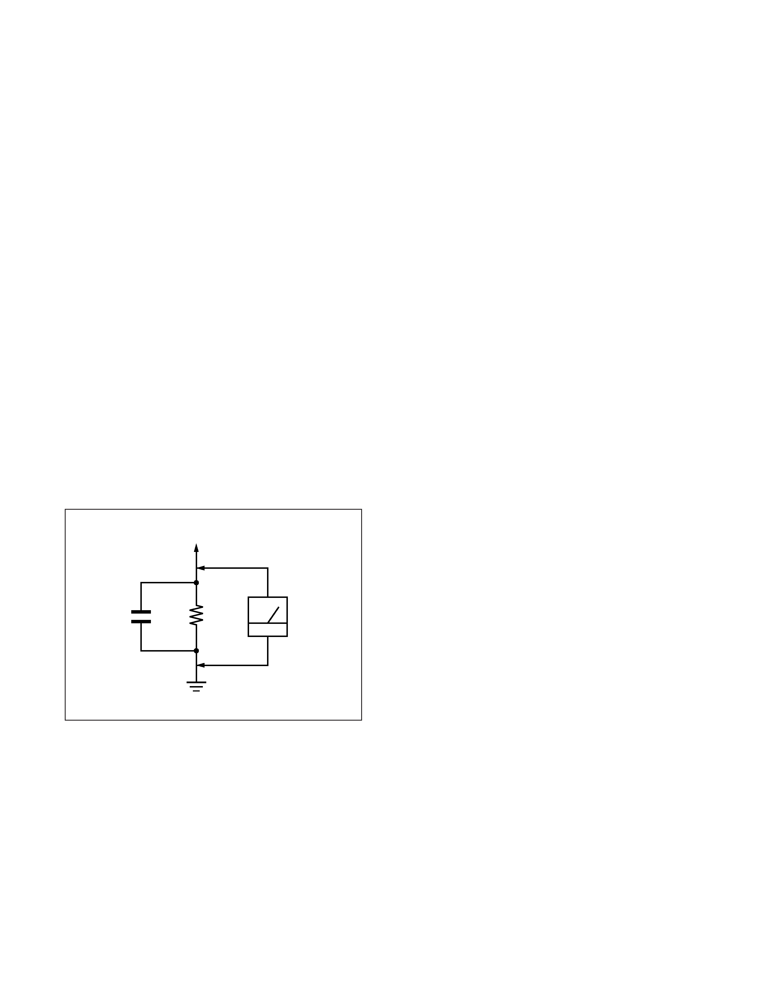
3. Measuring the voltage drop across a resistor by means of a
VOM or battery-operated AC voltmeter. The "limit" indica-
tion is 0.75 V, so analog meters must have an accurate low-
voltage scale. The Simpson 250 and Sanwa SH-63Trd are
examples of a passive VOMs that are suitable. Nearly all
battery operated digital multimeters that have a 2 V AC
range are suitable. (See Fig. A)
WARNING!!
NEVER TURN ON THE POWER IN A CONDITION IN
WHICH THE DEGAUSS COIL HAS BEEN REMOVED.
SAFETY-RELATED COMPONENT WARNING!!
COMPONENTS IDENTIFIED BY SHADING AND MARK
¡ ON THE SCHEMATIC DIAGRAMS, EXPLODED
VIEWS AND IN THE PARTS LIST ARE CRITICAL FOR
SAFE OPERATION. REPLACE THESE COMPONENTS
WITH SONY PARTS WHOSE PART NUMBERS AP-
PEAR AS SHOWN IN THIS MANUAL OR IN SUPPLE-
MENTS PUBLISHED BY SONY. CIRCUIT ADJUST-
MENTS THAT ARE CRITICAL FOR SAFE OPERATION
ARE IDENTIFIED IN THIS MANUAL. FOLLOW THESE
PROCEDURES WHENEVER CRITICAL COMPONENTS
ARE REPLACED OR IMPROPER OPERATION IS SUS-
PECTED.
AVERTISSEMENT!!
NE JAMAIS METTRE SOUS TENSION QUAND LA
BOBINE DE DEMAGNETISATION EST ENLEVÉE.
ATTENTION AUX COMPOSANTS RELATIFS À LA
SÉCURITÉ!!
LES COMPOSANTS IDENTIFIÉS PAR UNE TRAME ET
UNE MARQUE
¡ SONT CRITIQUES POUR LA SÉCURITÉ.
NE LES REMPLACER QUE PAR UNE PIÈCE PORTANT LE
NUMÉRO SPECIFIÉ. LES RÉGLAGES DE CIRCUIT DONT
L'IMPORTANCE EST CRITIQUE POUR LA SÉCURITÉ DU
FONCTIONNEMENT SONT IDENTIFIÉS DANS LE
PRÉSENT MANUEL. SUIVRE CES PROCÉDURES LORS
DE CHAQUE REMPLACEMENT DE COMPOSANTS CRI-
TIQUES, OU LORSQU'UN MAUVAIS FONCTIONNEMENT
EST SUSPECTÉ.
After correcting the original service problem, perform the fol-
lowing safety checks before releasing the set to the customer:
1. Check the area of your repair for unsoldered or poorly-sol-
dered connections. Check the entire board surface for solder
splashes and bridges.
2. Check the interboard wiring to ensure that no wires are
"pinched" or contact high-wattage resistors.
3. Check that all control knobs, shields, covers, ground straps,
and mounting hardware have been replaced. Be absolutely
certain that you have replaced all the insulators.
4. Look for unauthorized replacement parts, particularly tran-
sistors, that were installed during a previous repair. Point
them out to the customer and recommend their replacement.
5. Look for parts which, though functioning, show obvious
signs of deterioration. Point them out to the customer and
recommend their replacement.
6. Check the line cords for cracks and abrasion. Recommend
the replacement of any such line cord to the customer.
7. Check the B+ and HV to see if they are specified values.
Make sure your instruments are accurate; be suspicious of
your HV meter if sets always have low HV.
8. Check the antenna terminals, metal trim, "metallized"
knobs, screws, and all other exposed metal parts for AC
Leakage. Check leakage as described below.
Fig. A. Using an AC voltmeter to check AC leakage.
SAFETY CHECK-OUT
1.5 k
0.15
µF
AC
Voltmeter
(0.75 V)
To Exposed Metal
Parts on Set
Earth Ground
P1100
3
POWER SAVING FUNCTION
DIAGNOSIS
The energy saver feature has three different modes of operation:
s
Full Power
s
Standby/Suspend
s
Sleep
By selecting settings in the computer's Energy Saver utility, you are
able to determine the length of the inactivity period before the
monitor goes into sleep mode.
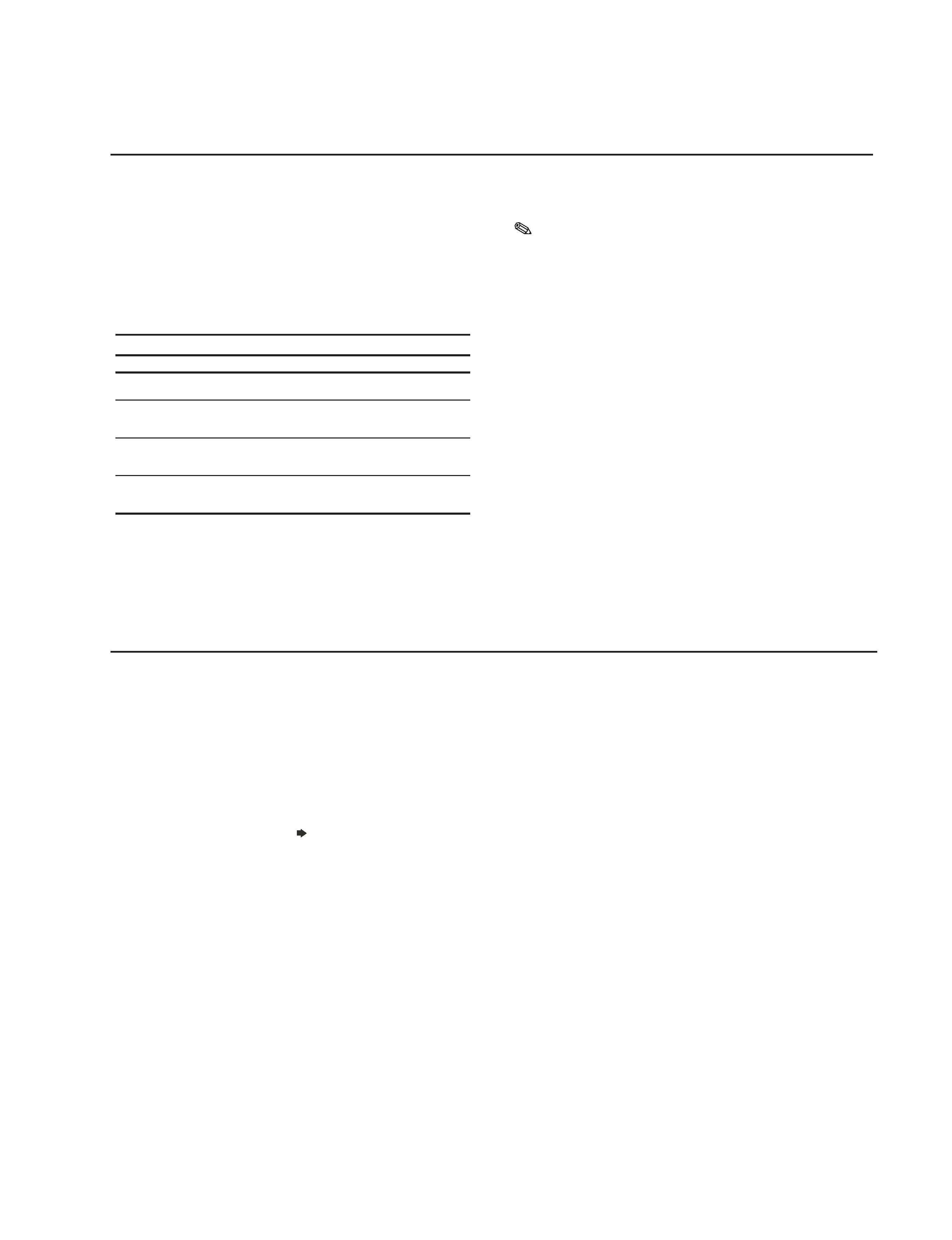
The following table describes the monitor energy saver levels
available during the different modes of operation.
Energy Saver Levels*
Mode
Power Usage
Description
Full Power
Less than 145 Watts ON = Normal operation
Power LED is green.
Standby/Suspend
Less than 15 Watts
Monitor screen is blank. LED blinks amber
and green. There is a brief warm-up
period before returning to full power mode.
Sleep
Approximately 1 Watt
Monitor screen is blank. LED turns amber.
There is a brief warm-up period before
returning to full power mode.
Off
0 Watts
Monitor screen is blank. LED is OFF. There
is a brief warm-up period before returning
to full power mode.
Refer to your computer manual for instructions on setting energy
saver features (sometimes referred to as power management
features).
The energy saver features for monitors only work when
connected to computers that have energy saver features.
s
Monitor is Working out of Scan Range, Change PC Settings
Indicates the monitor is unable to operate with the selected
input signal. Readjust your video setting to a lower resolution.
s
Monitor in Power Save Mode, Activate Using the PC
Indicates the monitor is in one of the power saving modes.
s
Monitor is Working, Check Signal Cable
Indicates the video cable may not be plugged into the
computer.
If the screen goes blank and the LED is green, remove any video
connections from video connector 1 or 2. You can also turn off the
PC. Press the power switch twice to turn the monitor OFF then ON
again. Press the right arrow button
(contrast increase) before the
monitor enters power saving mode. If a color bar pattern appears
then it is likely the problem is not the monitor. Please check the
condition of your computer. If the color bar pattern does not appear,
please inform your service representative of the monitor's condition.
If the power LED is flashing orange, please make note of the
frequency of flashing and inform your service representative of this
frequency.
P1100
4
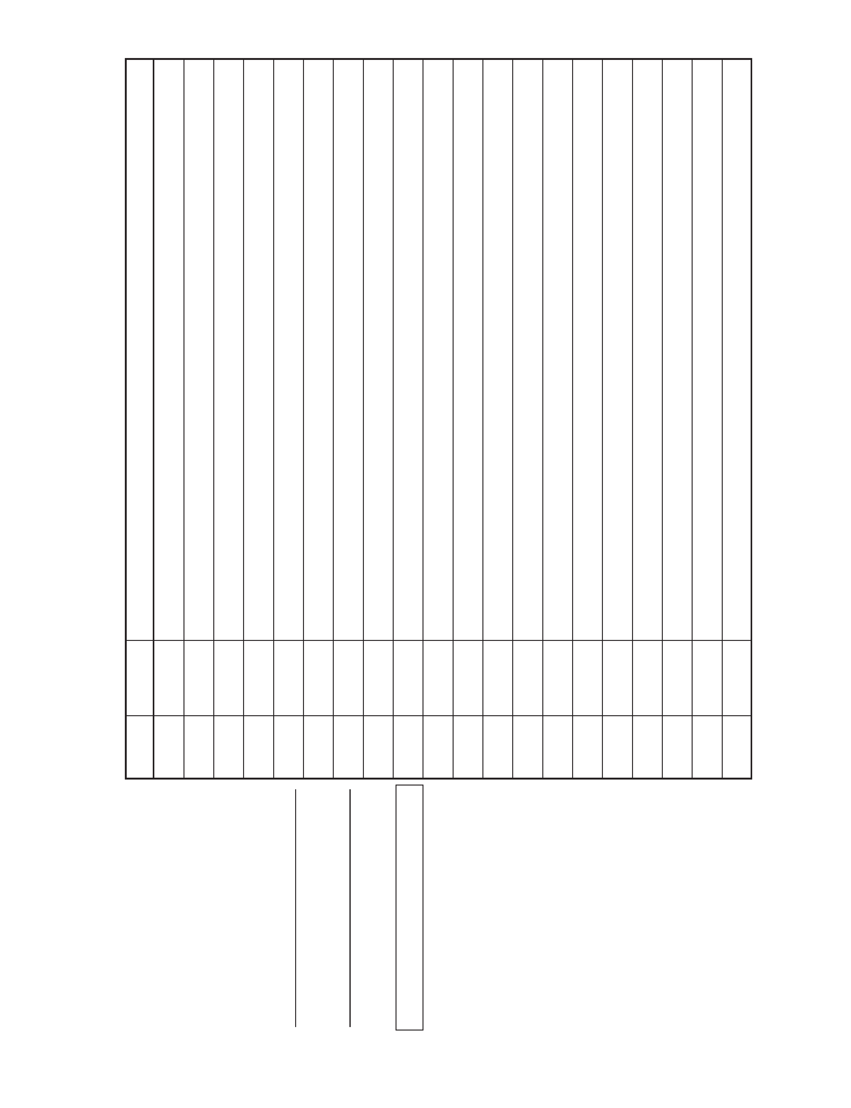
TIMING SPECIFICATION
MODE AT PRODUCTION
MODE 1
MODE 2
MODE 3
MODE 4
MODE 5
MODE 6
MODE 7
MODE 8
MODE 9
RESOLUTION
640 X 480
640 X 480
720 X 400
800 X 600
800 X 600
832 X 624
1024 X 768
1024 X 768
1152 X 870
CLOCK
25.175 MHz
36.000 MHz
28.322 MHz
49.500 MHz
56.250 MHz
57.283 MHz
78.750 MHz
94.500 MHz
100.000 MHz
-- HORIZONTAL --
H-FREQ
31.469 kHz
43.269 kHz
31.469 kHz
46.875 kHz
53.674 kHz
49.725 kHz
60.023 kHz
68.677 kHz
68.681 kHz
usec
usec
usec
usec
usec
usec
usec
usec
usec
H. TOTAL
31.778
23.111
31.777
21.333
18.631
20.111
16.660
14.561
14.560
H. BLK
6.356
5.333
6.355
5.172
4.409
5.586
3.657
3.725
3.040
H. FP
0.636
1.556
0.636
0.323
0.569
0.559
0.203
0.508
0.320
H. SYNC
3.813
1.556
3.813
1.616
1.138
1.117
1.219
1.016
1.280
H. BP
1.907
2.222
1.907
3.232
2.702
3.910
2.235
2.201
1.440
H. ACTIV
25.422
17.778
25.422
16.162
14.222
14.524
13.003
10.836
11.520
-- VERTICAL --
V. FREQ (HZ)
59.940 Hz
85.008 Hz
70.087 Hz
75.000 Hz
85.061 Hz
74.550 Hz
75.029 Hz
84.997 Hz
75.062 Hz
lines
lines
lines
lines
lines
lines
lines
lines
lines
V. TOTAL
525
509
449
625
631
667
800
808
915
V. BLK
45
29
49
25
31
43
32
40
45
V. FP
10
1
13
111
113
V. SYNC
2
32333
333
V. BP
33
25
34
21
27
39
28
36
39
V. ACTIV
480
480
400
600
600
624
768
768
870
-- SYNC --
INT(G)
NO
NO
NO
NO
NO
NO
NO
NO
NO
EXT (H/V) /POLARITY
YES N/N
YES N/N
YES N/P
YES P/P
YES P/P
YES N/N
YES P/P
YES P/P
YES N/N
EXT (CS) /POLARITY
NO
NO
NO
NO
NO
NO
NO
NO
NO
INT/NON INT
NON INT
NON INT
NON INT
NON INT
NON INT
NON INT
NON INT
NON INT
NON INT
MODE AT PRODUCTION
MODE 10
MODE 11
MODE 12
MODE 13
MODE 14
MODE 15
MODE 16
MODE 17
MODE 18
RESOLUTION
1280 X 1024
1280 X 1024
1280 X 1024
1600 X 1200
1600 X 1200
1792 X 1344
1792 X 1344
1920 X 1440
1920 X 1440
CLOCK
108.000 MHz
135.000 MHz
157.500 MHz
189.000 MHz
229.500 MHz
204.750 MHz
261.000 MHz
234.000 MHz
297.000 MHz
-- HORIZONTAL --
H-FREQ
63.981 kHz
79.976 kHz
91.146 kHz
87.500 kHz
106.250 kHz
83.640 kHz
106.270 kHz
90.000 kHz
112.500 kHz
usec
usec
usec
usec
usec
usec
usec
usec
usec
H. TOTAL
15.630
12.504
10.971
11.429
9.412
11.956
9.410
11.111
8.889
H. BLK
3.778
3.022
2.844
2.963
2.440
3.204
2.544
2.906
2.424
H. FP
0.444
0.119
0.406
0.339
0.279
0.625
0.368
0.547
0.485
H. SYNC
1.037
1.067
1.422
1.016
0.837
0.977
0.828
0.889
0.754
H. BP
2.296
1.837
1.016
1.608
1.325
1.602
1.349
1.470
1.185
H. ACTIV
11.852
9.481
8.127
8.466
6.972
8.752
6.866
8.205
6.465
-- VERTICAL --
V. FREQ (HZ)
60.020 Hz
75.025 Hz
85.024 Hz
70.000 Hz
85.000 Hz
60.000 Hz
74.997 Hz
60.000 Hz
75.000 Hz
lines
lines
lines
lines
lines
lines
lines
lines
lines
V. TOTAL
1066
1066
1072
1250
1250
1394
1417
1500
1500
V. BLK
42
42
48
50
50
50
73
60
60
V. FP
1
11111
111
V. SYNC
3
33333
333
V. BP
38
38
44
46
46
46
69
56
56
V. ACTIV
1024
1024
1024
1200
1200
1344
1344
1440
1440
-- SYNC --
INT(G)
NO
NO
NO
NO
NO
NO
NO
NO
NO
EXT (H/V) /POLARITY
YES P/P
YES P/P
YES P/P
YES P/P
YES P/P
YES N/P
YES N/P
YES N/P
YES N/P
EXT (CS) /POLARITY
NO
NO
NO
NO
NO
NO
NO
NO
NO
INT/NON INT
NON INT
NON INT
NON INT
NON INT
NON INT
NON INT
NON INT
NON INT
NON INT
99.09.06 VER.