SERVICE MANUAL
PORTABLE HARD DISK AUDIO PLAYER
US Model
Canadian Model
AEP Model
UK Model
SPECIFICATIONS
NW-HD1
Ver 1.1 2004.09
9-879-079-02
2004I05-1
© 2004.09
Sony Corporation
Personal Audio Company
Published by Sony Engineering Corporation
· SonicStage and SonicStage logo are trademarks or registered
trademarks of Sony Corporation.
· OpenMG, ATRAC3, ATRAC3plus and their logos are trademarks
of Sony Corporation.
· Microsoft, Windows, Windows NT and Windows Media are
trademarks or registered trademarks of Microsoft Corporation in
the United States and/or other countries.
· IBM and PC/AT are registered trademarks of International Business
Machines Corporation.
· Macintosh is a trademark of Apple Computer, Inc. in the United
States and/or other countries.
· Pentium is a trademark or a registered trademark of Intel
Corporation.
· Adobe and Adobe Reader are trademarks or registered trademarks
of Adobe Systems Incorporated in the United States and/or other
countries.
· US and foreign patents licensed from Dolby Laboratories.
· All other trademarks and registered trademarks are trademarks or
registered trademarks of their respective holders.
· In this manual, TM and ® marks are not specifi ed.
Maximum recordable number of track
(Approx.)*
ATRAC3
ATRAC3plus
5,000 (132 kbps)
2,500 (256 kbps)
6,000 (105 kbps)
10,000 (64 kbps)
10,000 (66 kbps)
13,000 (48 kbps)
* When transferring four-minute tracks
Sampling frequency
44.1 kHz
Audio compression technology
Adaptive Transform Acoustic Coding3 (ATRAC3),
Adaptive Transform Acoustic Coding3plus
(ATRAC3plus)
Frequency response
20 to 20,000 Hz
(single signal measurement during playback)
Output
i
(headphones)/LINE OUT* :
Stereo minijack/194 mV
* The jack is used for both headphones and LINE
OUT.
Operating temperature
5 to 35ºC (41 to 95ºF)
Power source
DC IN 6 V (from built-in rechargeable battery)
Battery life (continuous playback)
ATRAC3plus format (48 kbps): Approx. 30 hours
Dimension
Not including projecting parts:
89.0
× 62.1 × 13.8 (the thinnest part 12.6) mm
(3 5/8
× 2 1/2 × 9/16 (the thinnest part 1/2)
inches) (w/h/d)
Including projecting parts:
89.2
× 63.4 × 14.3 mm
(3 5/8
× 2 1/2 × 19/32 inches) (w/h/d)
Mass
Supplied accessories
Approx. 110 g (3.9 oz)
US and foreign patents licensed from Dolby
Laboratories.
· Headphones (1)
· USB cradle (1)
· Dedicated USB cable (1)
· AC power adaptor (1)
(For the supplied USB cradle)
· Carrying pouch (1)
· CD-ROM (1) *
(SonicStage, PDF of Operating Instructions)
· Quick Start Guide (1)
* Do not play this CD-ROM on an audio CD player.
Design and speci cations are subject to change
without notice.

2
NW-HD1
TABLE OF CONTENTS
1.
SERVICING NOTES ............................................... 3
2.
GENERAL ................................................................... 4
3.
DISASSEMBLY
3-1.
Disassembly Flow ...........................................................
5
3-2.
Cabinet (Upper) Sub Assy ...............................................
5
3-3.
Cabinet (Lower) Assy ......................................................
6
3-4.
Battery Block Sub Assy ...................................................
6
3-5.
MAIN Board ....................................................................
7
3-6.
LCD Block Sub Assy ......................................................
7
3-7.
HDD Unit, HDD Board ...................................................
8
4.
TEST MODE .............................................................. 9
5.
DIAGRAMS
5-1.
Block Diagram MAIN Section (1/2) .......................... 16
5-2.
Block Diagram MAIN Section (2/2) .......................... 17
5-3.
Block Diagram KEY/POWER SUPPLY Section ....... 18
5-4.
Printed Wiring Board
MAIN Section (Component Side) ............................. 20
5-5.
Printed Wiring Board
MAIN Section (Conductor Side) ............................... 21
5-6.
Schematic Diagram MAIN Section (1/7) ................... 22
5-7.
Schematic Diagram MAIN Section (2/7) ................... 23
5-8.
Schematic Diagram MAIN Section (3/7) ................... 24
5-9.
Schematic Diagram MAIN Section (4/7) ................... 25
5-10. Schematic Diagram MAIN Section (5/7) ................... 26
5-11. Schematic Diagram MAIN Section (6/7) ................... 27
5-12. Schematic Diagram MAIN Section (7/7) ................... 28
5-13. Printed Wiring Board HDD Section ......................... 29
5-14. Schematic Diagram HDD Section ............................ 29
6.
EXPLODED VIEW ................................................... 42
7.
ELECTRICAL PARTS LIST ................................ 43
Notes on chip component replacement
· Never reuse a disconnected chip component.
· Notice that the minus side of a tantalum capacitor may be
damaged by heat.
Flexible Circuit Board Repairing
· Keep the temperature of the soldering iron around 270 °C
during repairing.
· Do not touch the soldering iron on the same conductor of the
circuit board (within 3 times).
· Be careful not to apply force on the conductor when soldering
or unsoldering.
SAFETY-RELATED COMPONENT WARNING!!
COMPONENTS IDENTIFIED BY MARK 0 OR DOTTED LINE
WITH MARK 0 ON THE SCHEMATIC DIAGRAMS AND IN
THE PARTS LIST ARE CRITICAL TO SAFE OPERATION.
REPLACE THESE COMPONENTS WITH SONY PARTS WHOSE
PART NUMBERS APPEAR AS SHOWN IN THIS MANUAL OR
IN SUPPLEMENTS PUBLISHED BY SONY.
Notes on the AC power adaptor
Use only the AC power adaptor and USB
cradle supplied with the player. Do not use
any other AC power adaptor since this may
cause the player to malfunction.
The player is not disconnected from the
AC power source (mains) as long as it is
connected to the wall outlet, even if the
player itself has been turned off.
If you are not going to use the player for a
long time, be sure to disconnect the power
supply. To remove the AC power adaptor
from the wall outlet, grasp the adaptor plug
itself; never pull the cord.
ATTENTION AU COMPOSANT AYANT RAPPORT
À LA SÉCURITÉ!
LES COMPOSANTS IDENTIFIÉS PAR UNE MARQUE 0 SUR
LES DIAGRAMMES SCHÉMATIQUES ET LA LISTE DES
PIÈCES
SONT
CRITIQUES
POUR
LA
SÉCURITÉ
DE
FONCTIONNEMENT. NE REMPLACER CES COM- POSANTS
QUE PAR DES PIÈCES SONY DONT LES NUMÉROS SONT
DONNÉS DANS CE MANUEL OU DANS LES SUPPLÉMENTS
PUBLIÉS PAR SONY.
Ver 1.1

3
NW-HD1
SECTION 1
SERVICING NOTES
· Replacement of CXR704060-201GA (IC1003),
MBM29SL800BE-90PBT (IC1101), S1R72003BOOA100
(IC2001), CXR710160-211GH (IC3001), CXD1616GH
(IC7001) and EDL1216CASA-10L-E (IC7002) used in this
set requires a special tool.
UNLEADED SOLDER
Boards requiring use of unleaded solder are printed with the lead-
free mark (LF) indicating the solder contains no lead.
(Caution: Some printed circuit boards may not come printed with
the lead free mark due to their particular size)
: LEAD FREE MARK
Unleaded solder has the following characteristics.
· Unleaded solder melts at a temperature about 40 °C higher
than ordinary solder.
Ordinary soldering irons can be used but the iron tip has to be
applied to the solder joint for a slightly longer time.
Soldering irons using a temperature regulator should be set to
about 350 °C.
Caution: The printed pattern (copper foil) may peel away if
the heated tip is applied for too long, so be careful!
· Strong viscosity
Unleaded solder is more viscou-s (sticky, less prone to flow)
than ordinary solder so use caution not to let solder bridges
occur such as on IC pins, etc.
· Usable with ordinary solder
It is best to use only unleaded solder but unleaded solder may
also be added to ordinary solder.
System requirements
Computer
IBM PC/AT or Compatible
· CPU: Pentium II 400 MHz or higher (Pentium III 450 MHz or higher is
recommended.)
· Hard disk drive space: 200 MB or more (1.5 GB or more is recommended.) (The
amount of space will vary according to the Windows version and the number of
music les stored on the hard disk.)
· RAM: 64 MB or more (128 MB or more is recommended.)
Others
· CD drive (capable of digital playback by WDM)
· Sound Board
· USB port (Hi-Speed USB is supported.)
Operating System
Factory installed:
Windows XP Media Center Edition 2004/Windows XP Media Center Edition/
Windows XP Professional/Windows XP Home Edition/Windows 2000 Professional/
Windows Millennium Edition/Windows 98 Second Edition
Display
High Color (16 bit) or higher, 800 600 dots or better (1024
× 768 dots or better is
recommended.)
Others
· Internet access: for Web registration, EMD services and CDDB
· Windows Media Player (version 7.0 or higher) installed for playing WMA les
Notes
· SonicStage is not supported by the following environments:
Operating systems other than those the indicated above
Personally constructed PCs or operating systems
An environment that is an upgrade of the original manufacturer-installed operating system
Multi-boot environment
Multi-monitor environment
Macintosh
· We do not guarantee trouble-free operation on all computers that satisfy the system requirement.
· The NTFS format of Windows XP/Windows 2000 Professional can be used only with the standard (factory)
settings.
· For Windows 2000 Professional users, install Service Pack 3 or later version before using the software.
· We do not guarantee trouble-free operation of the system suspend, sleep, or hibernation function on the
computers.
4
NW-HD1
SECTION 2
GENERAL
This section is extracted from
instruction manual.
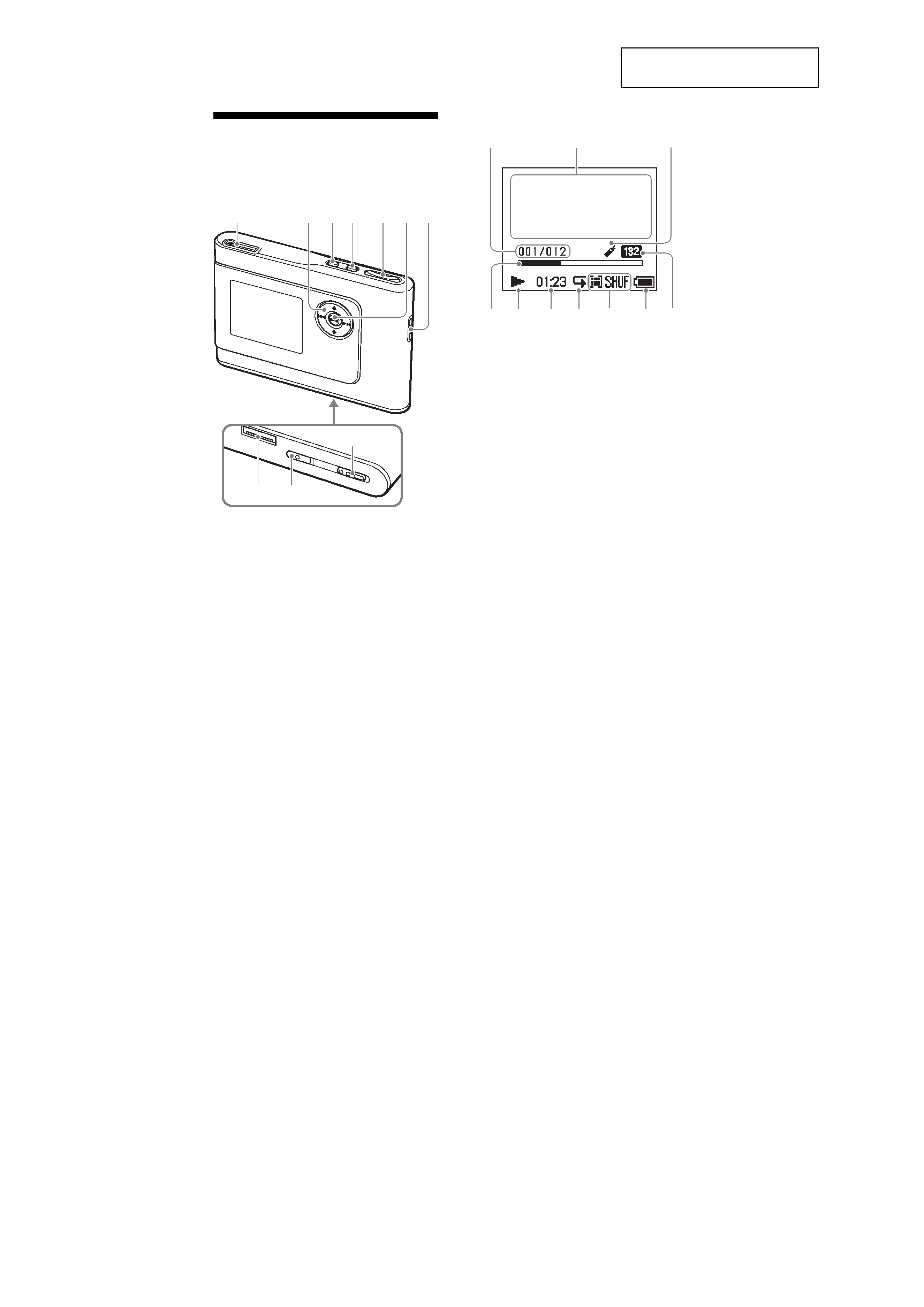
Guide to Parts and
Controls
Player
1
i
(headphones)/LINE OUT jack
2
M, m, ., >
buttons
3
MENU button
4
MODE button
5
VOLUME +*/ buttons
6
Nx (play/stop) button
7
Hole for hand strap**
8
USB cradle connector
9
BUILT-IN BATTERY switch
q;
HOLD switch
* This button has a tactile dot.
** You can attach your own hand strap.
Player display
qa
Track number indicator
qs
Character information display
qd
Bookmark indicator
qf
Playback progress bar
qg
Playback indicator
qh
Playing time
qj
Repeat indicator
qk
Play mode indicator
Sound indicator
ql
Battery indicator
w;
Bit rate
About the serial number
The serial number provided for this player is
required for the customer registration. The
number is on a label on the rear of the player.
8
12 3 4
5 6 7
qa
qs
qf
qg
qh
qj
qk
w;
ql
qd
9
q;
NW-HD1
5
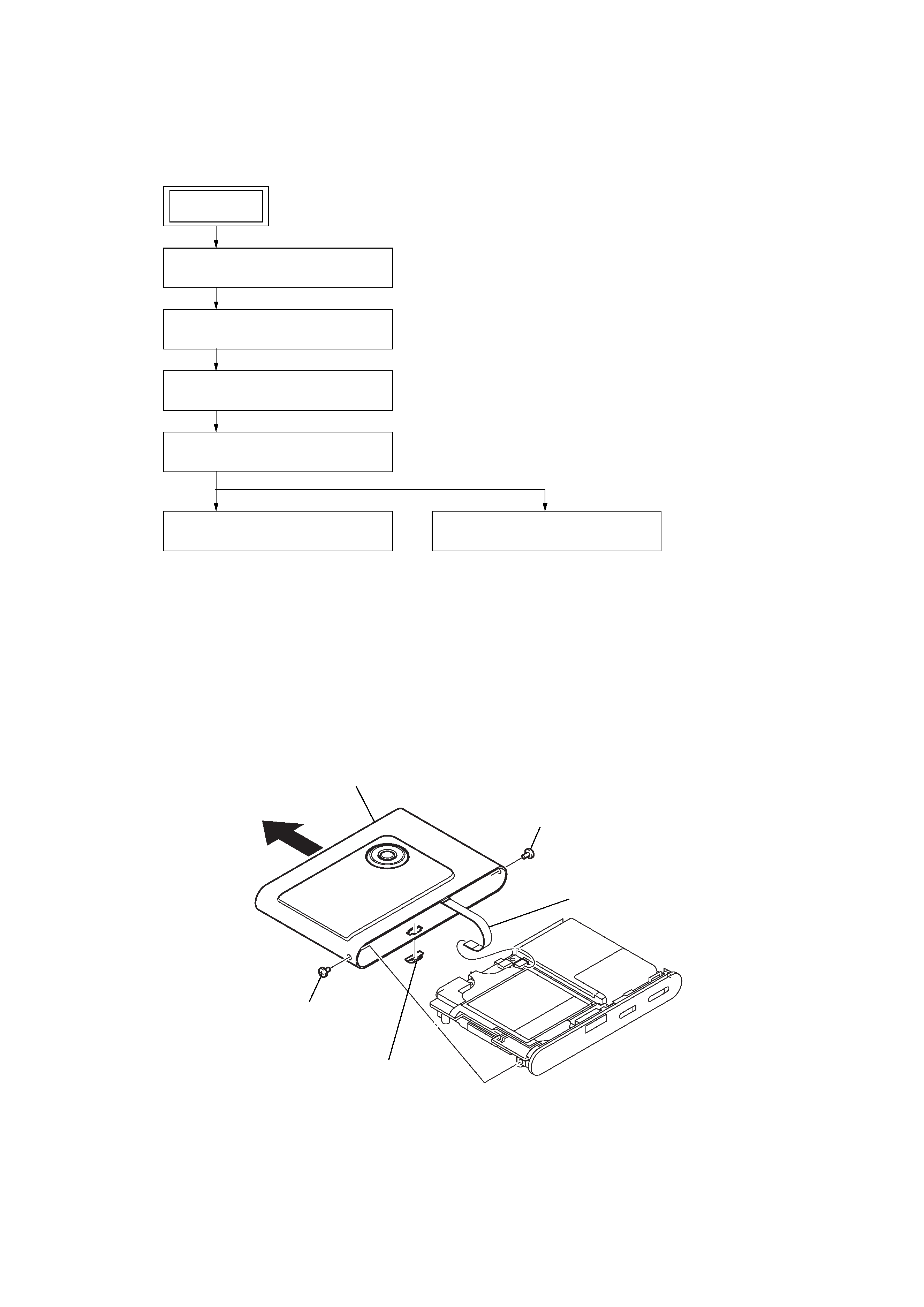
Note: Follow the disassembly procedure in the numerical order given.
3-2. CABINET (UPPER) SUB ASSY
· This set can be disassembled in the order shown below.
3-1. DISASSEMBLY FLOW
SECTION 3
DISASSEMBLY
3-2. CABINET (UPPER) SUB ASSY
(Page 5)
3-3. CABINET (LOWER) ASSY
(Page 6)
3-4. BATTERY BLOCK SUB ASSY
(Page 6)
3-5. MAIN BOARD
(Page 7)
3-6. LCD BLOCK SUB ASSY
(Page 7)
3-7. HDD UNIT, HDD BOARD
(Page 8)
SET
2
screw (M1.4)
6
cabinet (upper) sub assy
3
5
flexible board
(CN5002)
1
screw (M1.4)
4
escutcheon (cradle)