SERVICE MANUAL
Sony Corporation
Connect Company
Published by Sony Engineering Corporation
US Model
Canadian Model
AEP Model
E Model
Tourist Model
PORTABLE IC AUDIO PLAYER
9-879-316-06
2005I16-1
© 2005.09
Ver. 1.5 2005.09
SPECIFICATIONS
NW-E99
Sampling frequency
ATRAC3, ATRAC3plus, MP3: 44.1 kHz
Audio compression technology
Adaptive Transform Acoustic Coding3 (ATRAC3)
Adaptive Transform Acoustic Coding3plus
(ATRAC3plus)
MPEG1 Audio Layer-3 (MP3): 8 to 320 kbps,
variable bit rate-compliant
Frequency response
20 to 20,000 Hz (single signal measurement)
Output
Headphone: Stereo mini-jack
Supplied accessories
Headphones (1)
Dedicated USB cable (1)
Carrying pouch (1)
Neck strap (1)
Extension headphone cord (1)
CD-ROM for the SonicStage software (1)
Operating Instructions (1)
SonicStage Operating Instructions (1)
CD-ROM for the Operating Instructions and
SonicStage Operating Instructions (1)
Design and specifications are subject to
change without notice.
US and foreign patents licensed from Dolby
Laboratories.
Dynamic range
85 dB or more (excluding ATRAC3 66 kbps)
Operating temperature
5°C to 35°C (67°F to 95°F)
Power source
Size AAA (LR03) alkaline battery
Battery life (continuous
playback)
ATRAC3 format: Approximately 70 hours
(Playback at 105 kbps)
ATRAC3plus format: Approximately 60 hours
(Playback at 48 kbps)
MP3 format: Approximately 50 hours
(Playback at 128 kbps)
Dimension
56
× 37.3 × 15 mm (2 1/4 × 1 1/2 × 19/32 inches)
(w/h/d, projecting parts not included)
Mass
Approx. 40 g (2 oz) (battery not included)
Signal-to-noise ratio (S/N)
80 dB or more (excluding ATRAC3 66 kbps)
* The values for ATRAC3, ATRAC3plus apply if
the MP3 File Manager software has been erased
from the built-in flash memory.
ATRAC3plus*
8 hr. 00 min. (256 kbps)
34 hr. 20 min. (64 kbps)
46 hr. 40 min. (48 kbps)
ATRAC3*
16 hr. 40 min. (132 kbps)
21 hr. 00 min. (105 kbps)
33 hr. 40 min. (66 kbps)
MP3
8 hr. 00 min. (256 kbps)
16 hr. 00 min. (128 kbps)

2
NW-E99
TABLE OF CONTENTS
1.
GENERAL ................................................................... 3
2.
TEST MODE ............................................................... 5
3.
DISASSEMBLY
3-1.
Case, Chassis (Front) Assy ..............................................
6
3-2.
DISPLAY Board Assy .....................................................
7
3-3.
MAIN Board Assy ...........................................................
7
4.
DIAGRAMS
4-1.
Block Diagram ................................................................
9
4-2.
Printed Wiring Board
DISPLAY Board (Side A) ......................................... 10
4-3.
Printed Wiring Board
DISPLAY Board (Side B) ......................................... 11
4-4.
Schematic Diagram DISPLAY Board ....................... 12
4-5.
Printed Wiring Board MAIN Board (Side A) ............ 13
4-6.
Printed Wiring Board MAIN Board (Side B) ............ 14
4-7.
Schematic Diagram MAIN Board (1/2) .................... 15
4-8.
Schematic Diagram MAIN Board (2/2) .................... 16
5.
EXPLODED VIEWS
5-1.
Overall Assy Section ....................................................... 18
5-2.
MAIN Board Section ....................................................... 19
6.
ELECTRICAL PARTS LIST .................................. 20
Microsoft, Windows and Windows Media are trademarks or
registered trademarks of Microsoft Corporation in the United States
and/or other countries.
US and foreign patents licensed from Dolby Laboratories.
All other trademarks and registered trademarks are trademarks or
registered trademarks of their respective holders.
UNLEADED SOLDER
Boards requiring use of unleaded solder are printed with the lead-
free mark (LF) indicating the solder contains no lead.
(Caution: Some printed circuit boards may not come printed with
the lead free mark due to their particular size)
: LEAD FREE MARK
Unleaded solder has the following characteristics.
· Unleaded solder melts at a temperature about 40 °C higher
than ordinary solder.
Ordinary soldering irons can be used but the iron tip has to be
applied to the solder joint for a slightly longer time.
Soldering irons using a temperature regulator should be set to
about 350
°C.
Caution: The printed pattern (copper foil) may peel away if
the heated tip is applied for too long, so be careful!
· Strong viscosity
Unleaded solder is more viscou-s (sticky, less prone to flow)
than ordinary solder so use caution not to let solder bridges
occur such as on IC pins, etc.
· Usable with ordinary solder
It is best to use only unleaded solder but unleaded solder may
also be added to ordinary solder.
· IC400 (microcomputer) and IC450 (nor flash sram) on MAIN
board cannot be replaced individually.
Replace it with MAIN board assembly for service.
Flexible Circuit Board Repairing
· Keep the temperature of the soldering iron around 270 °C
during repairing.
· Do not touch the soldering iron on the same conductor of the
circuit board (within 3 times).
· Be careful not to apply force on the conductor when soldering
or unsoldering.
Notes on chip component replacement
· Never reuse a disconnected chip component.
· Notice that the minus side of a tantalum capacitor may be
damaged by heat.
3
NW-E99
SECTION 1
GENERAL
This section is extracted
from instruction manual.
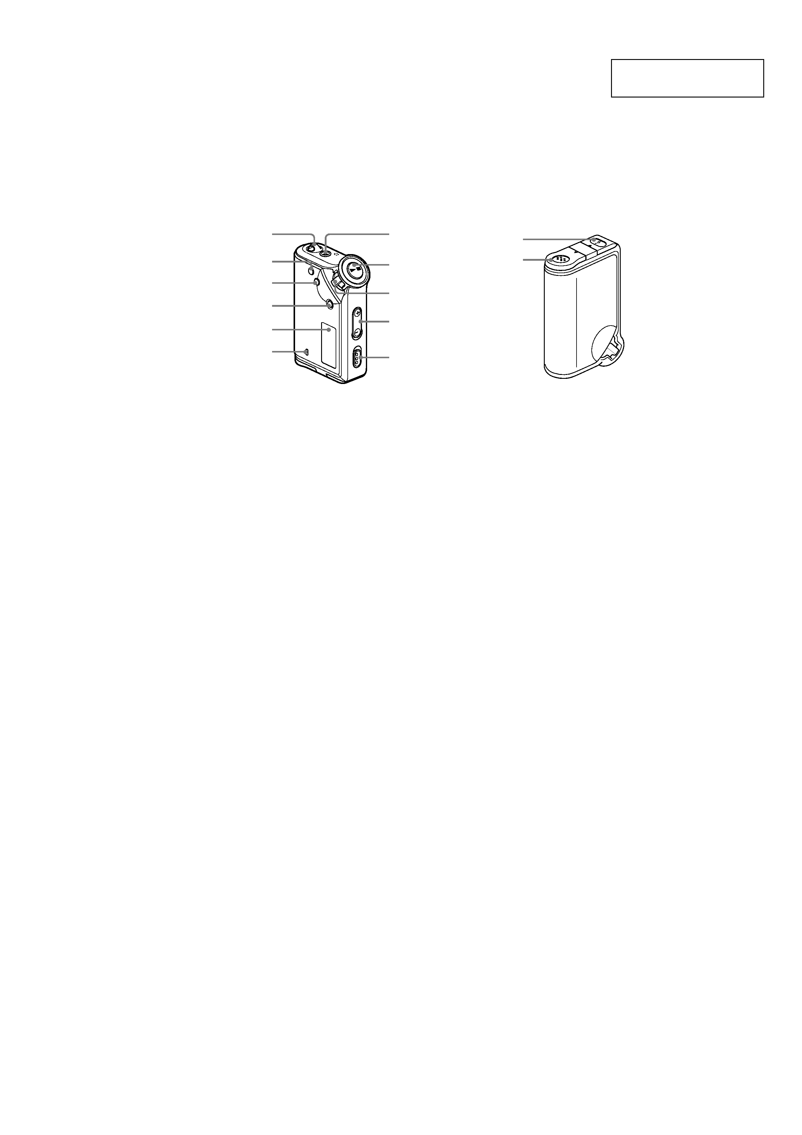
Locating controls
Rear side
Front side
7 Headphone jack
8
Nx button
0 VOLUME +/ button
qa HOLD (Locking controls) switch
qs USB jack
qd Battery compartment
Grou
p
M
o
d
e
1
2
3
4
5
6
7
8
9
0
qz
OPE
N
qs
qd
1 Strap hole for attaching the strap
2 REPEAT/SOUND button
3 MENU button
You can switch to the Time display by
pressing the MENU button for a while.
4 GROUP button
5 Display
6 ACCESS lamp
9 Shuttle switch
4
NW-E99
4 As you did in step 3, adjust the settings
for "month" and "date."
After rotating the Shuttle switch to adjust the
"date" setting and pressing the Nx button
to confirm, the display switches to the time
setting screen.
0:00
5 Rotate the Shuttle switch to adjust the
"hour" setting and press the Nx
button to confirm.
The "minute" digit blinks.
0:00
6 As you did in step 5, adjust the settings
for "minute."
After rotating the Shuttle switch to adjust the
"minute" setting and pressing the Nx
button to confirm, the display switches to the
time setting screen.
DA
T E- T IME
7 Press the MENU button.
The display returns to the normal screen.
Select [RETURN] in the menu screen or press the MENU
button.
Press the MENU button and hold it.
You can display the current time while pressing the
button.
Notes
· If the unit is not used for a long time, your settings of
the date and time may be reset.
· If the current time is not set, the display for the date and
time will be "-- --."
· If PC CLK is set to "ON", the time setting of your
Network Walkman is automatically adjusted to a
computer's built-in clock when your Network Walkman
is connected to the computer.
· Depending on the shipping area, the time display
format of the unit is set to a 12-hour display or a 24-
hour display.
You cannot switch between a 12-hour display and a 24-
hour display in the unit.
A 24-hour display is shown in this manual.
To cancel the menu mode
To display the current time
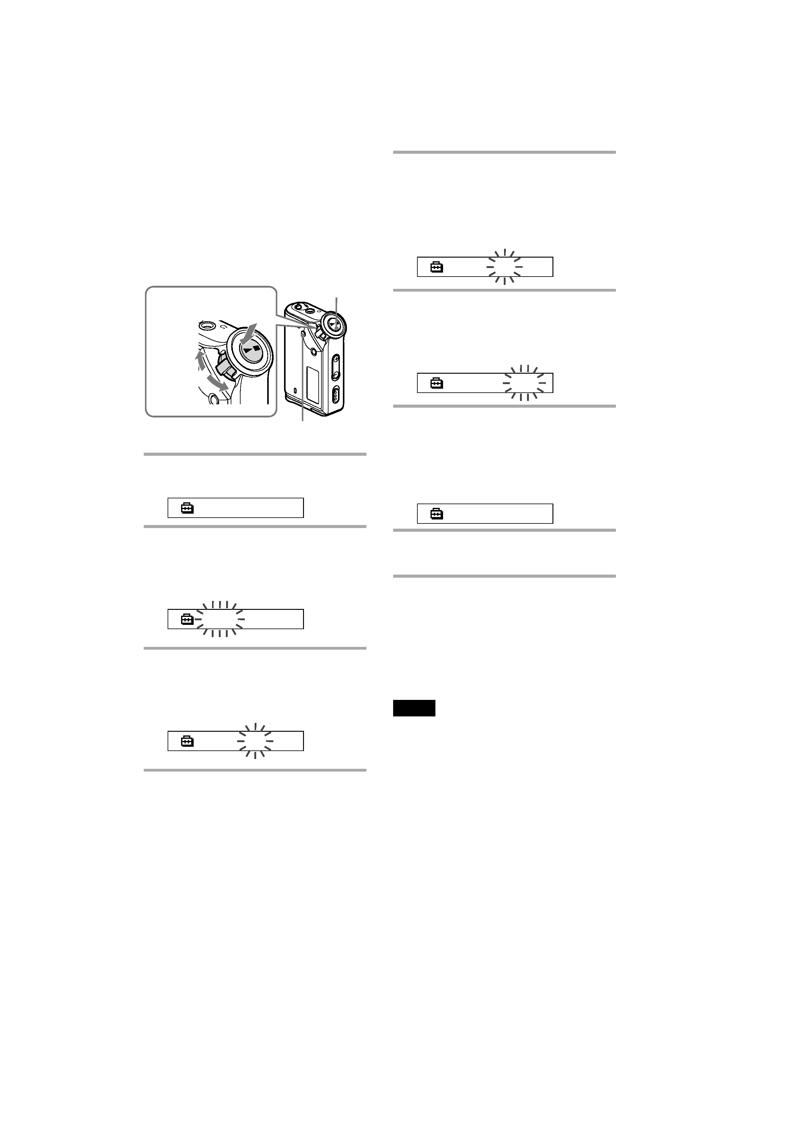
Adjusting the
current time
setting (DATE-
TIME)
You can set and display the current time.
1 Press the MENU button.
The menu screen is displayed.
REPE AT
MOD E
>
2 Rotate the Shuttle switch to select
"DATE-TIME" and press the Nx
button to confirm.
The "year" digit blinks.
2004y
1m
1d
3 Rotate the Shuttle switch to adjust the
"year" setting and press the Nx
button to confirm.
The "month" digit blinks.
2004y
1m
1d
Grou
p
M
o
d
e
o
d
e
Shuttle switch
Press
(Confirm)
Nx button
MENU button
to (+/>)
to (./)

5
NW-E99
SECTION 2
TEST MODE
STANDING PROCEDURE
Procedure 1: Set a dry battery into NW-E99, and keep the battery
lid open.
Procedure 2: In HOLD state, while pushing Nx and [GROUP]
button, turn power on by closing the battery lid of
NW-E99.
Procedure 3: Set HOLD state off.
After starting up test mode, the following contents can be checked.
TEST MODE
· Nx button
The KEY test mode is activated. All key inputs are completed,
then Nx button is pressed, restart. (Be aware that the
initialization is included on all key input.)
· [MENU] button
EL0 (blue) lights on/off.
· [GROUP] button
EL1 (green) lights on/off.
· -/>
All LCD lights and ACCESS LED lights off.
· ./+
All LCD lights and ACCESS LED lights on.
· [VOL +] button
BEEP turns on.
· [VOL --] button
BEEP turns off.
· [ REPEAT
SOUND] button
Initialized. (Turns to the factory preset state, time, volume setting
and so on.)
The music data, files and so on in the memory are not changed.
·