SERVICE MANUAL
DIGITAL MUSIC PLAYER
US Model
Canadian Model
AEP Model
UK Model
Australian Model
Korean Model
SPECIFICATIONS
NW-A1000
Ver. 1.0 2005.11
9-879-982-01
2005K05-1
© 2005.11
Sony Corporation
Connect Company
Published by Sony Engineering Corporation
Audio compression technology
- MPEG-1 Audio Layer-3 (MP3)
- Adaptive Transform Acoustic Coding (ATRAC)
Maximum recordable number of track and time (Approx.)*
Bit rate
Tracks
Time
48 kbps
4,000
266 hours, 40 minutes
64 kbps
3,000
200 hours
96 kbps
2,000
133 hours, 20 minutes
128 kbps
1,500
100 hours
132 kbps
1,500
100 hours
160 kbps
1,200
80 hours
192 kbps
1,000
66 hours, 40 minutes
256 kbps
750
50 hours
320 kbps
600
40 hours
* When transferring four-minute tracks
Supported bit rates
MP3: 32 to 320 kbps (supports variable bite rate (VBR))
ATRAC: 48/64/66 (ATRAC3)*/96/105 (ATRAC3)*/128/132
(ATRAC3)/160/192/256/320 kbps
* You cannot record CDs in ATRAC3 format at 66 or 105 kbps using
CONNECT Player.
Sampling frequencies
MP3: 44.1 kHz
ATRAC: 44.1 kHz
S/N Ratio
Headphones: 84 dB or more
LINE OUT: 96 dB or more
Frequency response
20 to 20,000 Hz (single signal measurement during playback)
Output
i (headphones)/LINE OUT*: Stereo minijack/195 mV (10
)
* The jack is used for both headphones and LINE OUT.
Operating temperature
5 to 35
°C (41 to 95°F)
Power source
Built-in rechargeable battery DC IN 5 V
AC power adaptor: DC IN 5 V
Battery life (continuous playback)
In ATRAC format (48 kbps), Display 15 sec
Approx. 20 hours
In ATRAC format (128 kbps), Display 15 sec
Approx. 17 hours
In MP3 format (128 kbps), Display 15 sec
Approx. 17 hours
Dimension (w/h/d)
Approx. 55.0 88.1 18.7 mm (11.5 mm at thinnest point)*
(2 1/4
× 3 1/2 × 3/4 inches) (15/32 inches at thinnest point)*
* Not including projecting parts.
Dimension including projecting part (w/h/d)
Approx. 55.0
× 88.1 × 18.7 mm
(2 1/4
× 3 1/2 × 3/4 inches)
Mass
Approx. 109 g (3.9 oz)
Supplied Accessories
Headphones (1)
USB cable (1)
Headphone extension cord (1)
AC power cord (1)
AC power adaptor (1)
CD-ROM (1) (CONNECT Player software, Operation Guide
(PDF file))
Quick Start Guide (1)
Design and specifications are subject to change without notice.
US and foreign patents licensed from Dolby Laboratories.

2
NW-A1000
TABLE OF CONTENTS
1.
SERVICING NOTES ............................................... 3
2.
GENERAL ................................................................... 4
3.
DISASSEMBLY
3-1.
Disassembly Flow ...........................................................
5
3-2.
Cabinet (Lower) ...............................................................
5
3-3.
Lithium Ion Battery .........................................................
6
3-4.
Cabinet (Inner) ................................................................
6
3-5.
EL Block Sub Assy ..........................................................
7
3-6.
MAIN Board ....................................................................
7
3-7.
Position of Ferrite Core ...................................................
8
4.
TEST MODE .............................................................. 9
5.
DIAGRAMS
5-1.
Block Diagram MAIN Section (1/2) ......................... 20
5-2.
Block Diagram MAIN Section (2/2) ......................... 21
5-3.
Block Diagram POWER SUPPLY Section ............... 22
5-4.
Printed Wiring Board
MAIN Board (Component Side) ............................... 24
5-5.
Printed Wiring Board
MAIN Board (Conductor Side) ................................. 25
5-6.
Schematic Diagram MAIN Board (1/8) .................... 26
5-7.
Schematic Diagram MAIN Board (2/8) .................... 27
5-8.
Schematic Diagram MAIN Board (3/8) .................... 28
5-9.
Schematic Diagram MAIN Board (4/8) .................... 29
5-10. Schematic Diagram MAIN Board (5/8) .................... 30
5-11. Schematic Diagram MAIN Board (6/8) .................... 31
5-12. Schematic Diagram MAIN Board (7/8) .................... 32
5-13. Schematic Diagram MAIN Board (8/8) .................... 33
6.
EXPLODED VIEW
6-1.
Cabinet Section ................................................................ 48
6-2.
MAIN Section ................................................................. 49
7.
ELECTRICAL PARTS LIST ................................ 50
Notes on chip component replacement
· Never reuse a disconnected chip component.
· Notice that the minus side of a tantalum capacitor may be
damaged by heat.
Flexible Circuit Board Repairing
· Keep the temperature of the soldering iron around 270 °C
during repairing.
· Do not touch the soldering iron on the same conductor of the
circuit board (within 3 times).
· Be careful not to apply force on the conductor when soldering
or unsoldering.
SAFETY-RELATED COMPONENT WARNING!!
COMPONENTS IDENTIFIED BY MARK 0 OR DOTTED LINE
WITH MARK 0 ON THE SCHEMATIC DIAGRAMS AND IN
THE PARTS LIST ARE CRITICAL TO SAFE OPERATION.
REPLACE THESE COMPONENTS WITH SONY PARTS WHOSE
PART NUMBERS APPEAR AS SHOWN IN THIS MANUAL OR
IN SUPPLEMENTS PUBLISHED BY SONY.
ATTENTION AU COMPOSANT AYANT RAPPORT
À LA SÉCURITÉ!
LES COMPOSANTS IDENTIFIÉS PAR UNE MARQUE 0 SUR
LES DIAGRAMMES SCHÉMATIQUES ET LA LISTE DES
PIÈCES
SONT
CRITIQUES
POUR
LA
SÉCURITÉ
DE
FONCTIONNEMENT. NE REMPLACER CES COM- POSANTS
QUE PAR DES PIÈCES SONY DONT LES NUMÉROS SONT
DONNÉS DANS CE MANUEL OU DANS LES SUPPLÉMENTS
PUBLIÉS PAR SONY.
3
NW-A1000
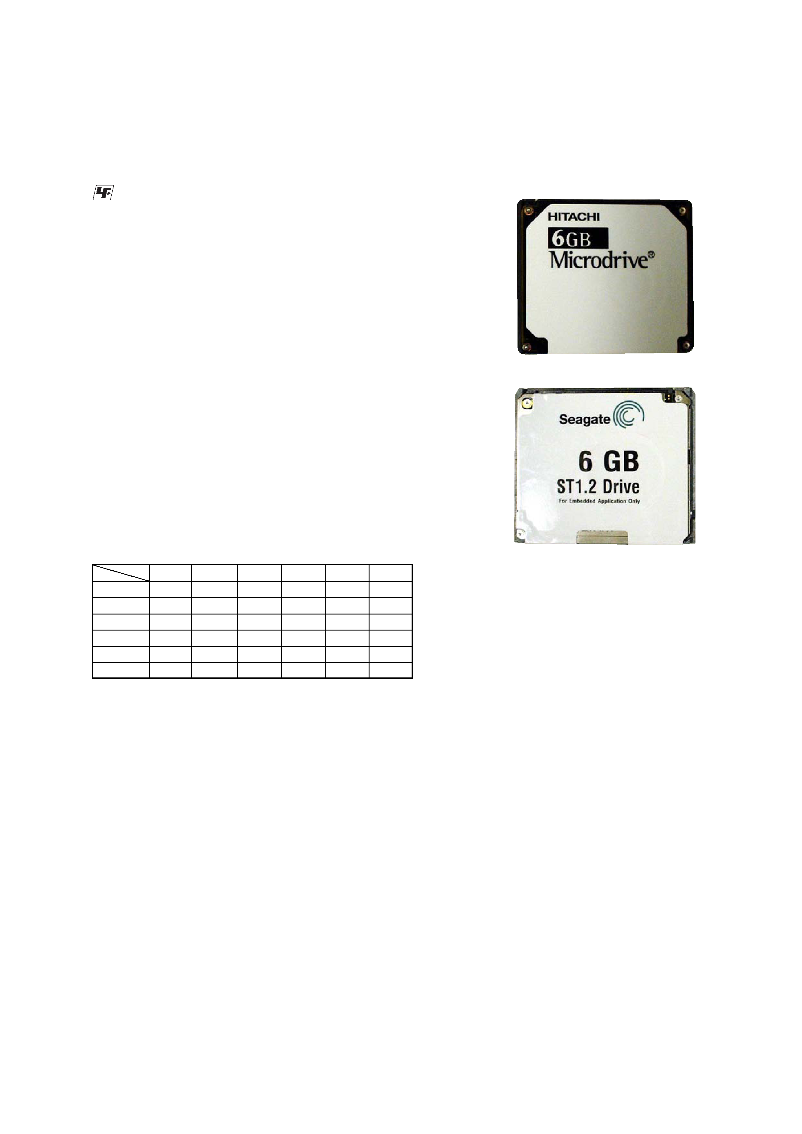
NOTES ON REPLACEMENT OF HDD UNIT
In this set, there are two kinds of HDD unit. (Refer to the figure
below)
Though either of parts for the repair is supplied, there is no problem
on the function even if which HDD unit is installed in the set.
HITACHI type
Seagate type
SECTION 1
SERVICING NOTES
UNLEADED SOLDER
Boards requiring use of unleaded solder are printed with the lead-
free mark (LF) indicating the solder contains no lead.
(Caution: Some printed circuit boards may not come printed with
the lead free mark due to their particular size)
: LEAD FREE MARK
Unleaded solder has the following characteristics.
· Unleaded solder melts at a temperature about 40 °C higher
than ordinary solder.
Ordinary soldering irons can be used but the iron tip has to be
applied to the solder joint for a slightly longer time.
Soldering irons using a temperature regulator should be set to
about 350 °C.
Caution: The printed pattern (copper foil) may peel away if
the heated tip is applied for too long, so be careful!
· Strong viscosity
Unleaded solder is more viscous (sticky, less prone to flow)
than ordinary solder so use caution not to let solder bridges
occur such as on IC pins, etc.
· Usable with ordinary solder
It is best to use only unleaded solder but unleaded solder may
also be added to ordinary solder.
NOTES ON REPLACEMENT OF CSP (CHIP SIZE
PACKAGE) IC
Replacement of CXR710160-215GH (IC3101), S1R72003BOOA100
(IC5001), SCF5250 (IC6005) , EDS1216AABH-75-E/KM (IC7001),
LC4128ZC-75MN132C (IC8001) and
µPD68855 (IC9001) used in
this set requires a special tool.
COLOR VARIATION
VIOLET SILVER
BLUE
PINK
BLACK
GOLD
US
zz
z
zz
z
Canadian
zz
z
z
AEP
zz
z
zz
z
UK
zz
z
zz
z
Australian
zz
z
z
Korean
zz
z
z
4
NW-A1000
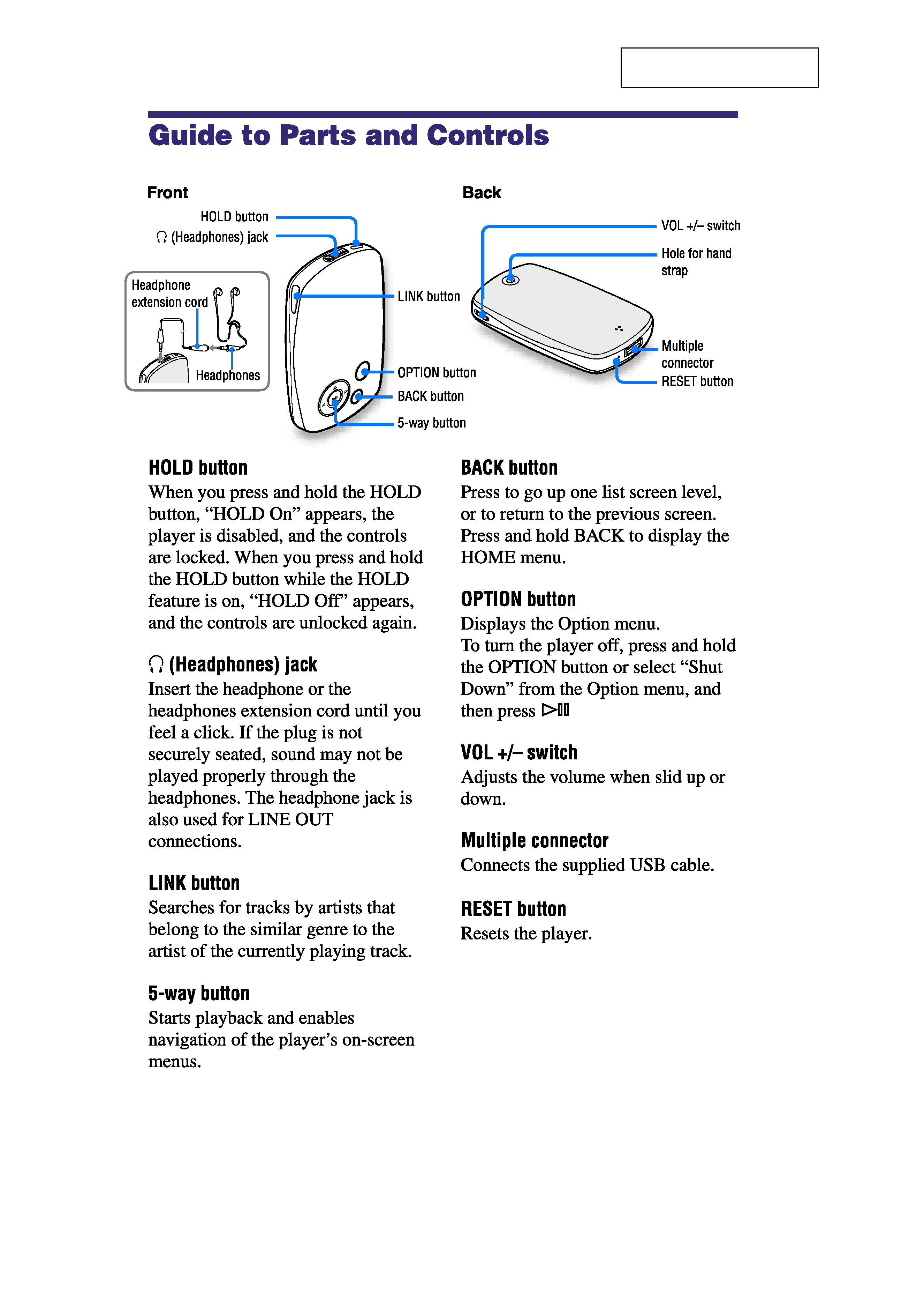
SECTION 2
GENERAL
This section is extracted from
instruction manual.
NW-A1000
5
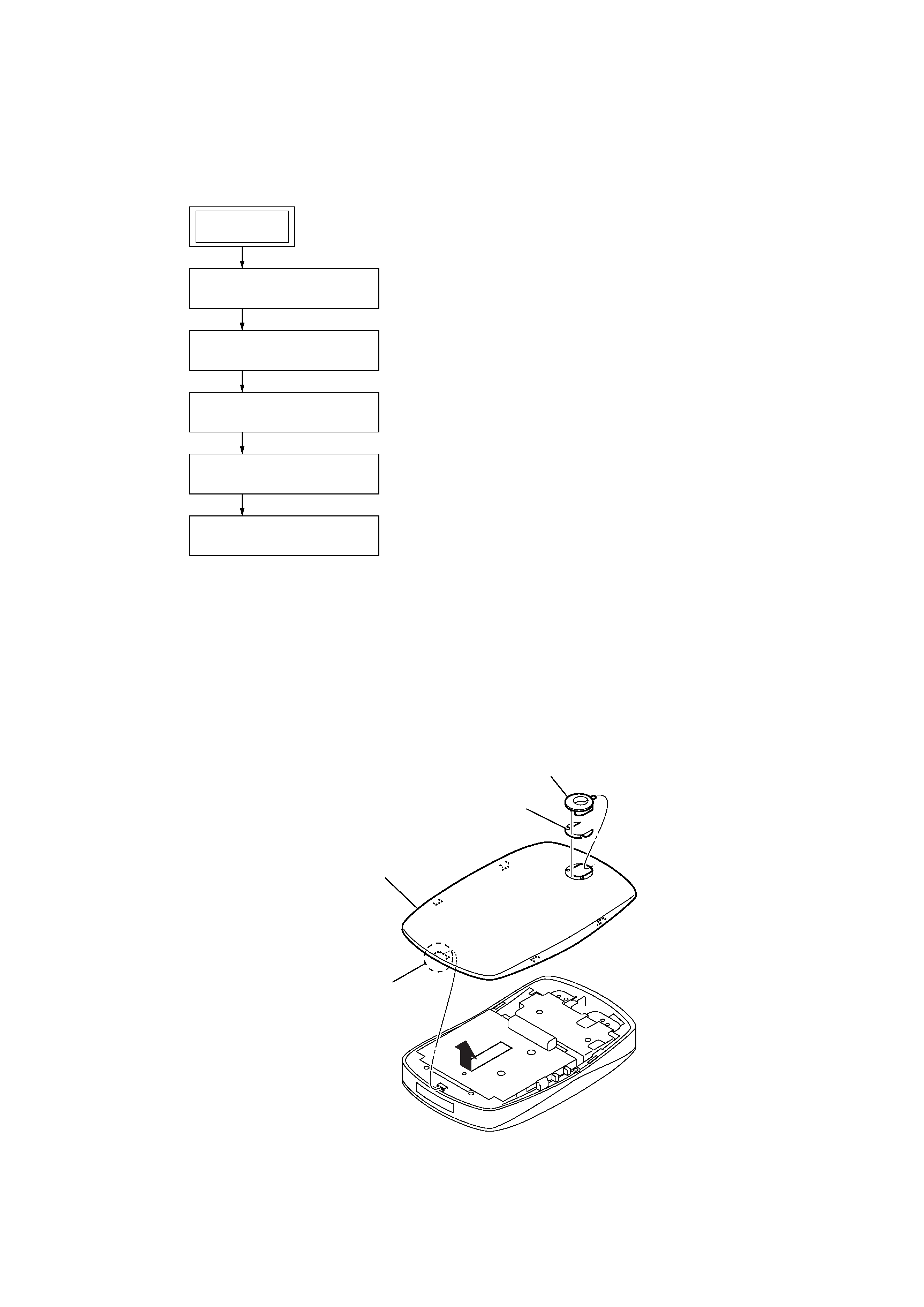
Note: Follow the disassembly procedure in the numerical order given.
3-2. CABINET (LOWER)
· This set can be disassembled in the order shown below.
3-1. DISASSEMBLY FLOW
SECTION 3
DISASSEMBLY
3
claw
1
ornament (strap)
2
adhesive sheet (strap)
4
Remove the cabinet (lower)
in the direction of the arrow.
Note: Execute the confirmation and the inspection of the correct repair of all parts after it repairs.
And, install ornament (strap) and adhesive sheet (strap) after confirming the repair ended completely.
3-2. CASE (LOWER)
(Page 5)
3-3. LITHIUM ION BATTERY
(Page 6)
3-4. CABINET (INNER)
(Page 6)
3-5. EL BLOCK SUB ASSY
(Page 7)
3-6. MAIN BOARD
(Page 7)
SET