SERVICE MANUAL
DIGITAL MUSIC PLAYER
US Model
Canadian Model
AEP Model
UK Model
Australian Model
Korean Model
SPECIFICATIONS
NW-A3000
Ver. 1.0 2005.11
9-879-979-01
2005K05-1
© 2005.11
Sony Corporation
Connect Company
Published by Sony Engineering Corporation
Continued on next page

2
NW-A3000
TABLE OF CONTENTS
1.
SERVICING NOTES ............................................... 3
2.
GENERAL ................................................................... 4
3.
DISASSEMBLY
3-1.
Disassembly Flow ...........................................................
5
3-2.
Cabinet (Lower) ...............................................................
5
3-3.
Cabinet (Upper) ...............................................................
6
3-4.
HP Board .........................................................................
6
3-5.
Battery Sub Assy .............................................................
7
3-6.
MAIN Board ....................................................................
7
3-7.
HDD Unit ........................................................................
8
3-8.
EL Sub Assy ....................................................................
8
3-9.
Position of Ferrite Core ...................................................
9
4.
TEST MODE ............................................................... 10
5.
DIAGRAMS
5-1.
Block Diagram MAIN Section (1/2) ......................... 20
5-2.
Block Diagram MAIN Section (2/2) ......................... 21
5-3.
Block Diagram POWER SUPPLY Section ............... 22
5-4.
Printed Wiring Board
MAIN Board (Component Side) ............................... 24
5-5.
Printed Wiring Board
MAIN Board (Conductor Side) ................................. 25
5-6.
Schematic Diagram MAIN Board (1/8) .................... 26
5-7.
Schematic Diagram MAIN Board (2/8) .................... 27
5-8.
Schematic Diagram MAIN Board (3/8) .................... 28
5-9.
Schematic Diagram MAIN Board (4/8) .................... 29
5-10. Schematic Diagram MAIN Board (5/8) .................... 30
5-11. Schematic Diagram MAIN Board (6/8) .................... 31
5-12. Schematic Diagram MAIN Board (7/8) .................... 32
5-13. Schematic Diagram MAIN Board (8/8) .................... 33
5-14. Printed Wiring Board HP Board ................................ 34
5-15. Schematic Diagram HP Board .................................. 34
5-16. Printed Wiring Board CONNECTOR Board ............ 35
5-17. Schematic Diagram CONNECTOR Board ............... 35
6.
EXPLODED VIEW
6-1.
Cabinet Section ................................................................ 50
6-2.
Main Section .................................................................... 51
7.
ELECTRICAL PARTS LIST ................................ 52
Notes on chip component replacement
· Never reuse a disconnected chip component.
· Notice that the minus side of a tantalum capacitor may be
damaged by heat.
Flexible Circuit Board Repairing
· Keep the temperature of the soldering iron around 270 °C
during repairing.
· Do not touch the soldering iron on the same conductor of the
circuit board (within 3 times).
· Be careful not to apply force on the conductor when soldering
or unsoldering.
SAFETY-RELATED COMPONENT WARNING!!
COMPONENTS IDENTIFIED BY MARK 0 OR DOTTED LINE
WITH MARK 0 ON THE SCHEMATIC DIAGRAMS AND IN
THE PARTS LIST ARE CRITICAL TO SAFE OPERATION.
REPLACE THESE COMPONENTS WITH SONY PARTS WHOSE
PART NUMBERS APPEAR AS SHOWN IN THIS MANUAL OR
IN SUPPLEMENTS PUBLISHED BY SONY.
ATTENTION AU COMPOSANT AYANT RAPPORT
À LA SÉCURITÉ!
LES COMPOSANTS IDENTIFIÉS PAR UNE MARQUE 0 SUR
LES DIAGRAMMES SCHÉMATIQUES ET LA LISTE DES
PIÈCES
SONT
CRITIQUES
POUR
LA
SÉCURITÉ
DE
FONCTIONNEMENT. NE REMPLACER CES COM- POSANTS
QUE PAR DES PIÈCES SONY DONT LES NUMÉROS SONT
DONNÉS DANS CE MANUEL OU DANS LES SUPPLÉMENTS
PUBLIÉS PAR SONY.
Supplied Accessories
Headphones (1)
USB cable (1)
Headphone extension cord (1)
AC power cord (1)
AC power adaptor (1)
CD-ROM (1)
(CONNECT Player software, Operation Guide (PDF file))
Quick Start Guide (1)
3
NW-A3000
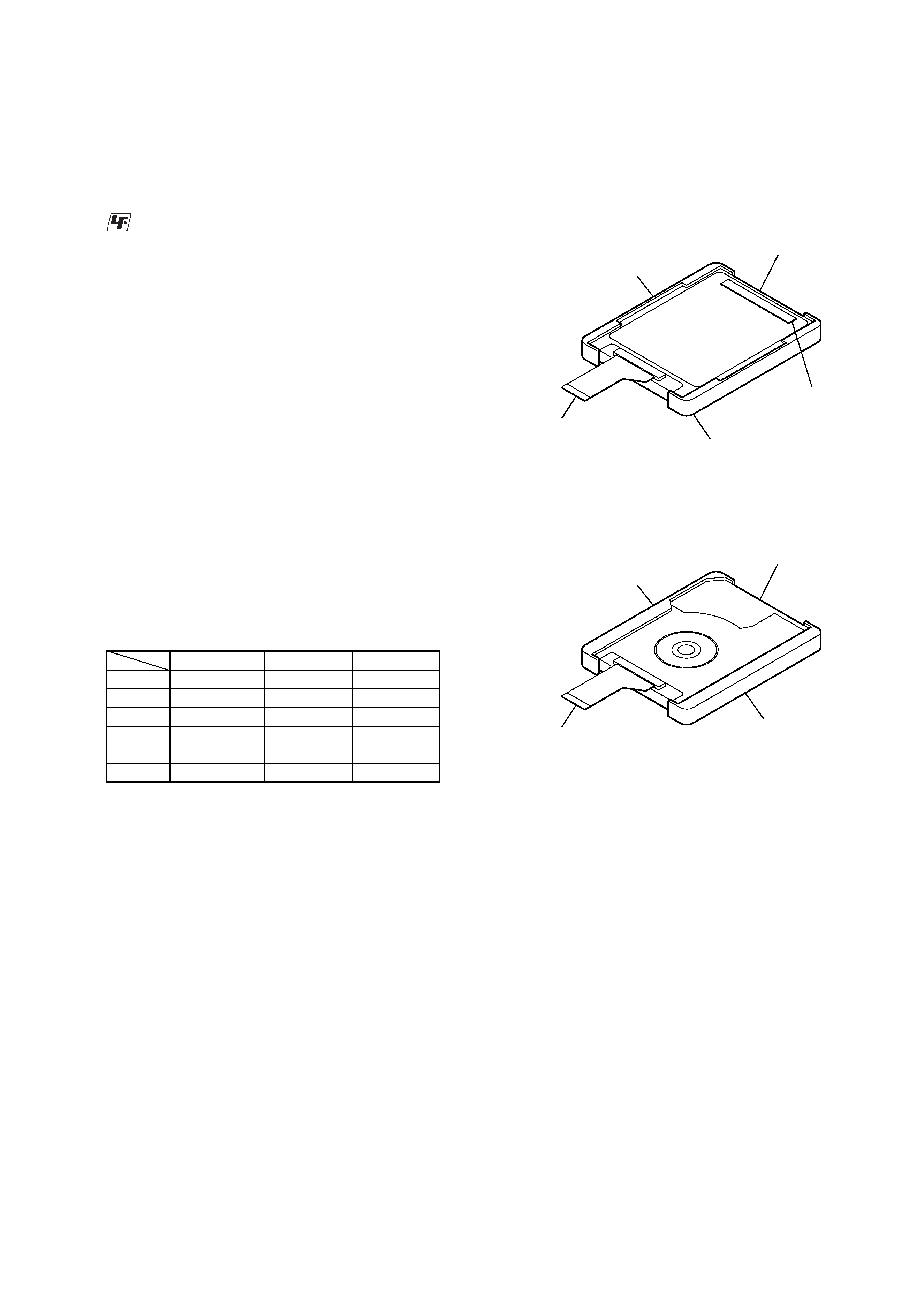
DESCRIPTION OF HDD UNIT SECTION AND NOTES
ON REPLACEMENT OF HDD UNIT SECTION
In this set,there are two kinds of HDD unit section. Exchange it for
parts that suit the repair set according to the figure below.
SECTION 1
SERVICING NOTES
UNLEADED SOLDER
Boards requiring use of unleaded solder are printed with the lead-
free mark (LF) indicating the solder contains no lead.
(Caution: Some printed circuit boards may not come printed with
the lead free mark due to their particular size)
: LEAD FREE MARK
Unleaded solder has the following characteristics.
· Unleaded solder melts at a temperature about 40 °C higher
than ordinary solder.
Ordinary soldering irons can be used but the iron tip has to be
applied to the solder joint for a slightly longer time.
Soldering irons using a temperature regulator should be set to
about 350 °C.
Caution: The printed pattern (copper foil) may peel away if
the heated tip is applied for too long, so be careful!
· Strong viscosity
Unleaded solder is more viscous (sticky, less prone to flow)
than ordinary solder so use caution not to let solder bridges
occur such as on IC pins, etc.
· Usable with ordinary solder
It is best to use only unleaded solder but unleaded solder may
also be added to ordinary solder.
NOTES ON REPLACEMENT OF CSP (CHIP SIZE
PACKAGE) IC
Replacement of CXR710160-215GH (IC3101), S1R72003BOOA100
(IC5001), SCF5250 (IC6005) , K4M281633H-BG75 (IC7001),
LC4128ZC-75MN132C (IC8001) and
µPD68855 (IC9001) used in
this set requires a special tool.
COLOR VARIATION
VIOLET
SILVER
BLACK
US
zz
z
Canadian
zz
AEP
zz
z
UK
zz
z
Australian
zz
Korean
zz
Part No. : 1-868-525-11
Description: flexible board
Part No. : 2-653-380-01
Description: insulator (T1.8)
Part No. : 1-479-528-11
Description: HDD unit (20GB)
HDD UNIT Section (for TOSHIBA)
HDD UNIT Section (for HITACHI)
Part No. : 2-653-380-01
Description: insulator (T1.8)
Part No. : 2-629-604-61
Description: cushion
(HDD1.5)
Part No. : 1-868-526-11
Description: flexible board
Part No. : 2-653-382-01
Description:insulator (HL1.8)
Part No. : 1-479-527-11
Description: HDD unit (20GB)
Part No. : 2-653-383-01
Description: insulator (HR1.8)
4
NW-A3000
SECTION 2
GENERAL
This section is extracted from
instruction manual.
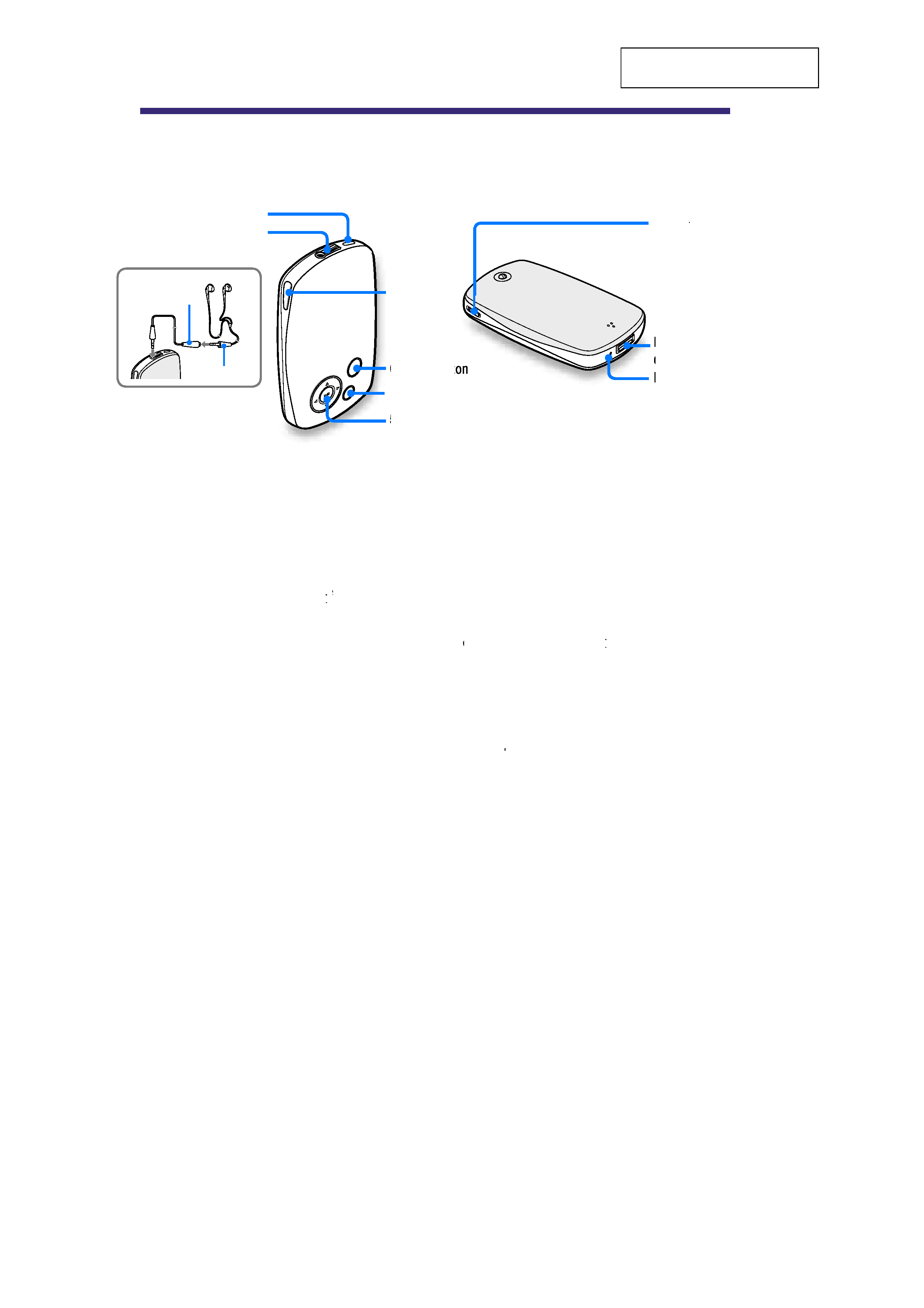
Guide to Parts and Controls
HOLD button
When you press and hold the HOLD
button, "HOLD On" appears, the
player is disabled, and the controls
are locked. When you press and hold
the HOLD button while the HOLD
feature is on, "HOLD Off
ff "
ff appears,
and the controls are unlocked again.
i
(Headphones) jack
Insert the headphone or the
headphones extension cord until you
feel a click. If the plug is not
securely seated, sound may not be
played properly through the
headphones. The headphone jack is
also used for LINE OUT
connections.
LINK button
Searches for tracks by artists that
belong to the similar genre to the
artist of the currently playing track.
5-way button
Starts playback and enables
navigation of the player's on-screen
menus.
BACK button
Press to go up one list screen level,
or to return to the previous screen.
Press and hold BACK to display the
HOME menu.
OPTION button
Displays the Option menu.
To turn the player of
T
T
f, press and hold
ff
the OPTION button or select "Shut
Down" from the Option menu, and
then press 7
VOL +/
// switch
Adjusts the volume when slid up or
down.
Multiple connector
Connects the supplied USB cable.
RESET button
Resets the player.
Front
i
(Headphones) jack
HOLD button
LINK button
OPTION butt
BACK button
5-way button
Headphones
Headphone
extension cord
Back
VOL +/
// switch
Multiple
connector
RESET button
NW-A3000
5
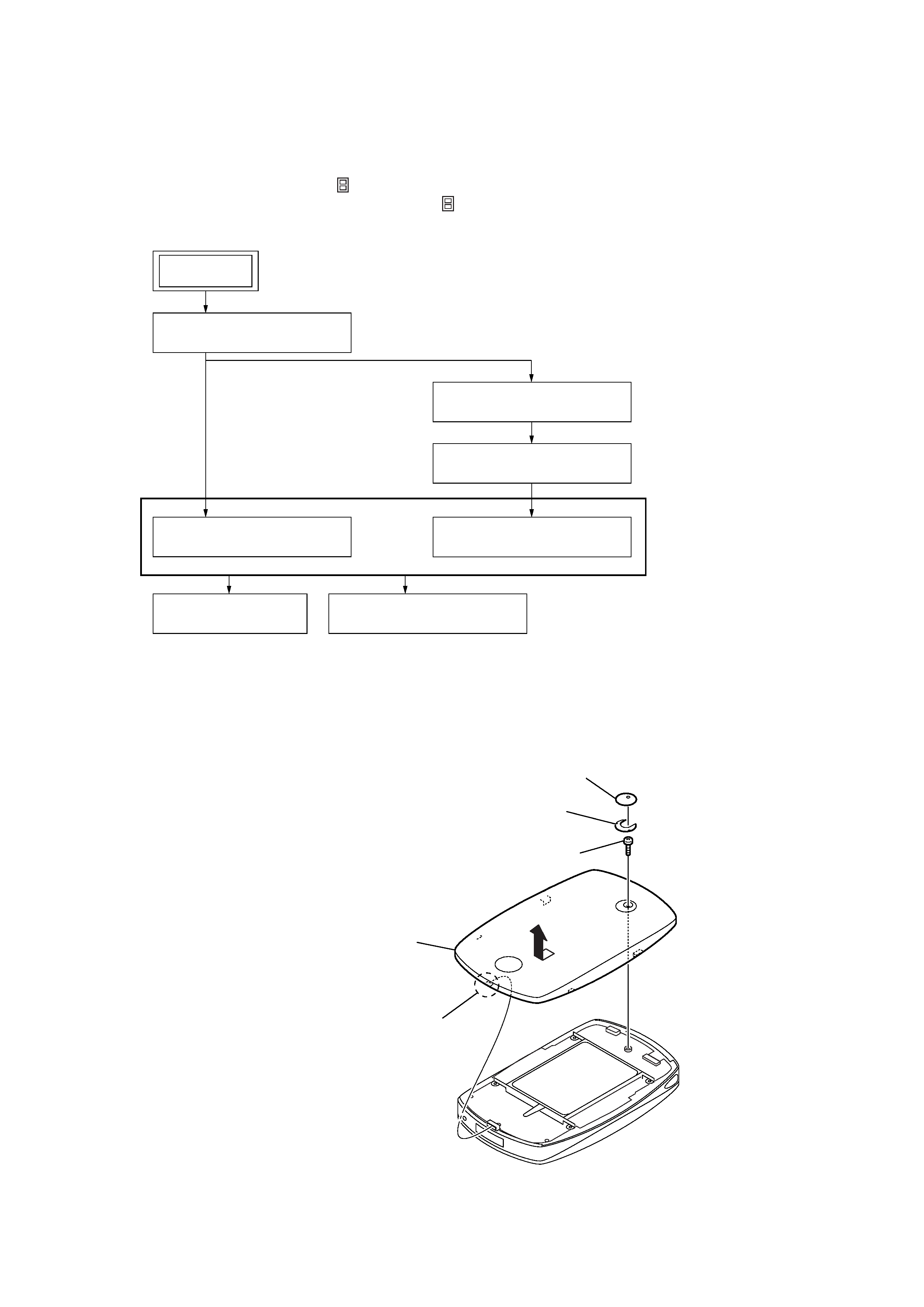
Note: Follow the disassembly procedure in the numerical order given.
3-2. CABINET (LOWER)
· This set can be disassembled in the order shown below.
3-1. DISASSEMBLY FLOW
Note 1: The process described in
can be performed in any order.
Note 2: Without completing the process described in
, the next process can not be performed.
Note 3: Illustration of disassembly is omitted.
SECTION 3
DISASSEMBLY
4
claw
5
Remove the cabinet (lower)
in the direction of the arrow.
1
emblem (W dot)
3
screw (1.4
× 3)
2
adhesive sheet
(emblem)
Note:Execute the confirmation and the inspection of the correct repair of all parts
after it repairs. And, install emblem (W dot) and adhesive sheet (emblem)
after confirming the repair ended completely.
3-2. CABINET (LOWER)
(Page 5)
3-5. BATTERY SUB ASSY
(Page 7)
3-6. MAIN BOARD
(Page 7)
3-7. HDD UNIT
(Page 8)
3-3. CABINET (UPPER)
(Page 6)
3-8. EL SUB ASSY
(Page 8)
3-4. HP BOARD
(Page 6)
SET