SERVICE MANUAL
d impedance 10
Audio playing system
MiniDisc digital audio system
Laser diode properties
Material: GaAlAs
Wavelength: = 790 nm
Emission dura tion : continuous
Laser output: less than 44. 6
µW
(This output is the va lue measured at a distance
of 200 mm from the lens surface on the optical
pick-up block with 7 mm a per ture .)
Recording and playback time
When using MDW-80:
Ma ximum 160 min. in monaura l
Ma ximum 320 min. in ste reo
Revolutions
350 rpm to 2, 800 rpm (CLV)
Error correction
ACIRC (Advanced Cross Interleave Reed
Solomon Code)
Sampling frequency
44.1 kHz
Sampling rate converter
Input: 32 kHz/44. 1 kHz/48 kHz
Coding
ATRAC (Adaptive TRa nsform Acoust ic
Coding)
ATRAC3 -- LP2
ATRAC3 -- LP4
Modulation system
EFM (Eight to Fourteen Modula tion)
Number of channels
2 s ter eo channels
1 mona ura l channel
Frequency response
20 to 20, 000 Hz
± 3 dB
Inputs
Micropho ne : stereo mini-jack, minimum input
leve l 0. 25 mV
Line in1): s tereo mini-ja ck, minimum input
leve l 49 mV
Op tical (Digital) in
1)
: optical (digital) mini-ja ck
Outputs
i/LINE OUT2): s tereo mini-jack
headphones/earphones: maximum output
leve l 5 mW + 5 mW, loa d impedance 16 oh m
LINE OUT: 19 4 mV, loa
kilohm
Power requirements
Sony AC P owe r Ada ptor connecte d a t the DC
IN 3V jack:
23 0 - 240 V AC, 50 Hz (UK and Hong kong models)
22 0 V AC, 50 Hz (Chinese model)
23 0 V AC, 50 /60 Hz (Europe continental model)
10 0 - 240 V AC, 50 /60 Hz (Other models)
Nicke l meta l hydr ide rechageable battery NH-
14WM(A) 1.2V 1350 mAh (MIN) Ni-MH
LR6 (s ize AA) alkaline battery
Dimensions 3)
Approx. 78 .9
× 72. 0 × 17. 1 mm (w/h/d)
(31/8
× 27/8 × 11/16 in.)
Mass
Approx. 11 0 g (3.9 oz ) the recorder only
1)The LINE IN (OP T) jack is used to connect
e ither a digital (optica l) cable or a line
(a nalog) cable.
2)The i/LINE OUT jack connector eithe r
headphones/earphones or a line ca ble .
3)Measured in accordance with JEITA.
Battery operating time
Battery life 1)
When recording 2)
(Unit: approx hours)(JE ITA
3))
1) The battery life may be shorter due to operating
conditions and the tempreture of the location.
2) Whe n you record, use a fully charged
rechargeable ba tter y. Reco rding time may
diffe r according to the a lka line batteries.
Batteries
SP
Stere o
LP2
Stere o
LP4
Stereo
NH-14WM
nickel metal
hydride
rechargeable
battery 4)
8.5
11
14
LR6 (S G)
S ony alkaline
dry battery 5)
7.5
12
15
NH-14WM
nicke l meta l
hydride
rechargeable
battery 4)
+ One LR6
(SG) 5)
20
28
37
Below measurable limit
Wow and Flutter
PORTABLE MINIDISC RECORDER
AEP Model
UK Model
E Model
Chinese Model
Australian Model
Tourist Model
SPECIFICATIONS
MZ-R909
US and foreign patents licensed from Dolby
Laboratories.
Continued on next page
Model Name Using Similar Mechanism
NEW
Mechanism Type
MT-MZR909-171
Optical Pick-up Name
LCX-4R
Ver 1.2 2002. 01
9-873-285-03
Sony Corporation
2002A0500-1
Personal Audio Company
C
2002.01
Published by Sony Engineering Corporation
2
MZ-R909
TABLE OF CONTENTS
1.
SERVICING NOTES ............................................... 3
2.
GENERAL ................................................................... 4
3.
DISASSEMBLY
3-1. Disassembly Flow ...........................................................
5
3-2. Panel Assy, Bottom .........................................................
5
3-3. Panel Assy, Upper Section ..............................................
6
3-4. "LCD Module", "Panel Assy, Upper" ............................
6
3-5. MAIN Board Assy ..........................................................
7
3-6. "Case Assy, Battery", "MAIN Board" ...........................
7
3-7. Strip, Ornamental ............................................................
8
3-8. "MD Mechanism Deck (MT-MZR909-171)",
"Chassis Assy, Set" .........................................................
8
3-9. Service Assy, OP (LCX-4R) ...........................................
9
3-10. Holder Assy ..................................................................... 10
3-11. Motor, DC (Sled) (M602) ............................................... 10
3-12. "Motor, DC (Spindle) (M601)",
"Motor, DC (Over Write Head UP/DOWN) (M603)" ... 11
4.
TEST MODE .............................................................. 12
5.
ELECTRICAL ADJUSTMENTS ......................... 18
6.
DIAGRAMS
6-1. Block Diagram SERVO Section ............................... 34
6-2. Block Diagram AUDIO Section ............................... 35
6-3. Block Diagram KEY CONTROL/DISPLAY/
POWER SUPPLY Section ........................................... 36
6-4. Note for Printed Wiring Boards and
Schematic Diagrams ....................................................... 37
6-5. Printed Wiring Board
Main Board (Component Side) ............................... 38
6-6. Printed Wiring Board
Main Board (Conductor Side) ................................. 39
6-7. Schematic Diagram Main Board (1/4) .................... 40
6-8. Schematic Diagram Main Board (2/4) .................... 41
6-9. Schematic Diagram Main Board (3/4) .................... 42
6-10. Schematic Diagram Main Board (4/4) .................... 43
6-11. IC Pin Function Description ........................................... 48
7.
EXPLODED VIEWS
7-1. Panel Section ................................................................... 54
7-2. Chassis Section ............................................................... 55
7-3. MD Mechanism Deck Section (MT-MZR909-171) ....... 56
8.
ELECTRICAL PARTS LIST ............................... 57
SAFETY-RELATED COMPONENT WARNING!!
COMPONENTS IDENTIFIED BY MARK 0 OR DOTTED
LINE WITH MARK 0 ON THE SCHEMATIC DIAGRAMS
AND IN THE PARTS LIST ARE CRITICAL TO SAFE
OPERATION. REPLACE THESE COMPONENTS WITH
SONY PARTS WHOSE PART NUMBERS APPEAR AS
SHOWN IN THIS MANUAL OR IN SUPPLEMENTS PUB-
LISHED BY SONY.
Design and specifications are subject to change
without notice.
When playing
(Unit: approx.hours)(JE ITA1))
Batteries
S P
Stereo
LP2
Stereo
LP4
Stere o
NH-14WM
nickel metal
hydride
rechargeable
battery 2)
24
27
31
LR6 (S G)
Sony alkaline
dry battery 3)
34
40
45
NH-14WM
nickel metal
hydride
rechargeable
battery 2)
+ On e LR6
(SG) 3)
64
75
84
1) Measured in a ccordance with the J EITA
(J apan Electronics and Informat ion
Te ch nology Indus trie s Ass ociat ion) s tan da rd.
2) When using a 100% fully charged
rechargeable ba tte ry.
3) When using a Sony LR6 (S G) "STAMINA "
a lka line dry batte ry (produce d in Ja pan)
On power sources
· Us e house current, nickel me tal hydride
rechargeable batte ry, LR6 (s ize AA) battery.
or car battery.
· For use in your house: For the s uppl ied batte ry
charging s ta nd, use the AC po wer adaptor
s uppl ied with this re corder. Do not use any other
AC power adaptor s ince it ma y cause the re corder
to ma lfuncti on.
P olarity of the
plug
AC power adap tor (1)
Headphones/earphones with a remote control
(1)
Ba tte ry cha rging sta nd (Asse mbly needed) (1)
Rechargeable battery (1)
Dry battery case (1)
Rechargeable ba tte ry carrying cas e (1)
Carrying pouch/ca rrying case with a belt clip
(1)
AC plug adaptor (Exce pt Europe, China
and HongKong models) (1)
Optica l cable (1)
Supplied accessories
3) Measured in accordance with the J EITA (J a pa n
Electronic s a nd Informa tion Technology
Indust rie s Associa tion) standard.
4) Whe n using a 100 % fully charged rechargeable
battery.
5) Whe n us ing a S ony LR6 (S G) " STAMINA "
a lka line dry battery (produce d in Japan).
CAUTION
Use of controls or adjustments or performance of procedures
other than those specified herein may result in hazardous ra-
diation exposure.
Ver 1.1
3
MZ-R909
NOTES ON HANDLING THE OPTICAL PICK-UP
BLOCK OR BASE UNIT
The laser diode in the optical pick-up block may suffer electro-
static break-down because of the potential difference generated
by the charged electrostatic load, etc. on clothing and the human
body.
During repair, pay attention to electrostatic break-down and also
use the procedure in the printed matter which is included in the
repair parts.
The flexible board is easily damaged and should be handled with
care.
NOTES ON LASER DIODE EMISSION CHECK
Never look into the laser diode emission from right above when
checking it for adjustment. It is feared that you will lose your sight.
NOTES ON HANDLING THE OPTICAL PICK-UP BLOCK
(LCX-4R)
The laser diode in the optical pick-up block may suffer electro-
static break-down easily. When handling it, perform soldering
bridge to the laser-tap on the flexible board. Also perform mea-
sures against electrostatic break-down sufficiently before the op-
eration. The flexible board is easily damaged and should be handled
with care.
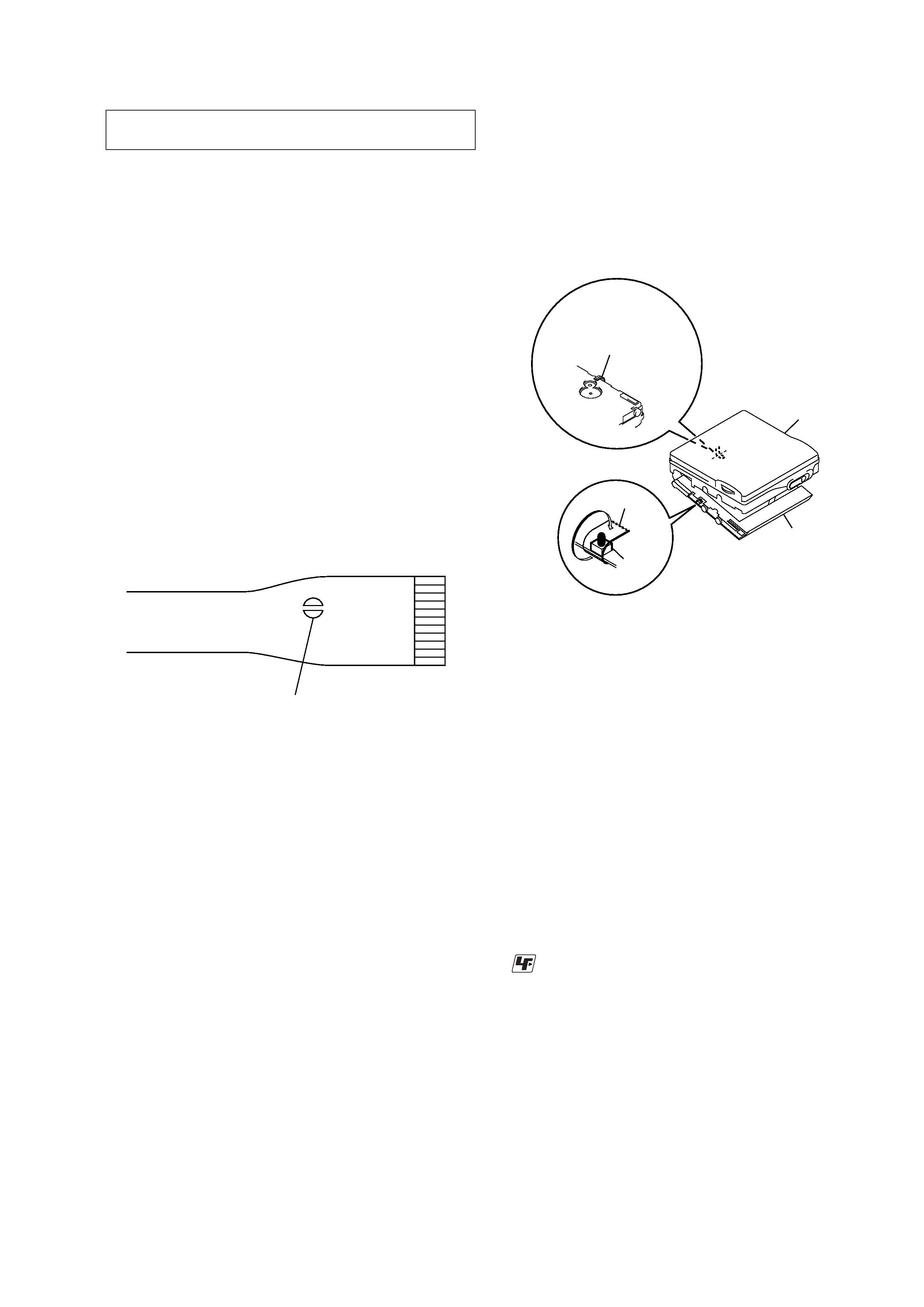
OPTICAL PICK-UP FLEXIBLE BOARD
SECTION 1
SERVICING NOTES
· In performing the repair with the power supplied to the set,
removing the MAIN board causes the set to be disabled.
In such a case, fix a convex part of the open/close detect switch
(S806 on MAIN board) with a tape in advance.
Handle the FLEXIBLE board (overwrite head) with care, as it
has been soldered directly to the MAIN board.
In repairing the component side of MAIN board, connect the
FLEXIBLE board (overwrite head) and the MAIN board with
the lead wires in advance. (See page 7)
laser-tap
upper panel assy
MAIN board
Tape
S806
FLEXIBLE board
(Over write head)
· Replacement of CXD2671-209GA (IC801) used in this set re-
quires a special tool.
· The shipment data will be cleared when the NV is reset. There-
fore, change the adjusted values following the Change of Ad-
justed Values immediately after the NV was reset. (See page
18)
· If the nonvolatile memory was replaced on the set, the modified
program data must be written to the nonvolatile memory. In such
a case, write the modified data that meets the microcomputer
version following the patch data rewriting procedure at the
replacement of nonvolatile memory. (See page 23)
Notes on chip component replacement
· Never reuse a disconnected chip component.
· Notice that the minus side of a tantalum capacitor may be dam-
aged by heat.
Flexible Circuit Board Repairing
· Keep the temperature of the soldering iron around 270 °C dur-
ing repairing.
· Do not touch the soldering iron on the same conductor of the
circuit board (within 3 times).
· Be careful not to apply force on the conductor when soldering
or unsoldering.
UNLEADED SOLDER
Boards requiring use of unleaded solder are printed with the lead-
free mark (LF) indicating the solder contains no lead.
(Caution: Some printed circuit boards may not come printed with
the lead free mark due to their particular size)
: LEAD FREE MARK
Unleaded solder has the following characteristics.
· Unleaded solder melts at a temperature about 40 °C higher than
ordinary solder.
Ordinary soldering irons can be used but the iron tip has to be
applied to the solder joint for a slightly longer time.
Soldering irons using a temperature regulator should be set to
about 350 °C .
Caution: The printed pattern (copper foil) may peel away if the
heated tip is applied for too long, so be careful!
· Strong viscosity
Unleaded solder is more viscous (sticky, less prone to flow) than
ordinary solder so use caution not to let solder bridges occur
such as on IC pins, etc.
· Usable with ordinary solder
It is best to use only unleaded solder but unleaded solder may
also be added to ordinary solder.
4
MZ-R909
SECTION 2
GENERAL
This section is extracted from
instruction manual.
8
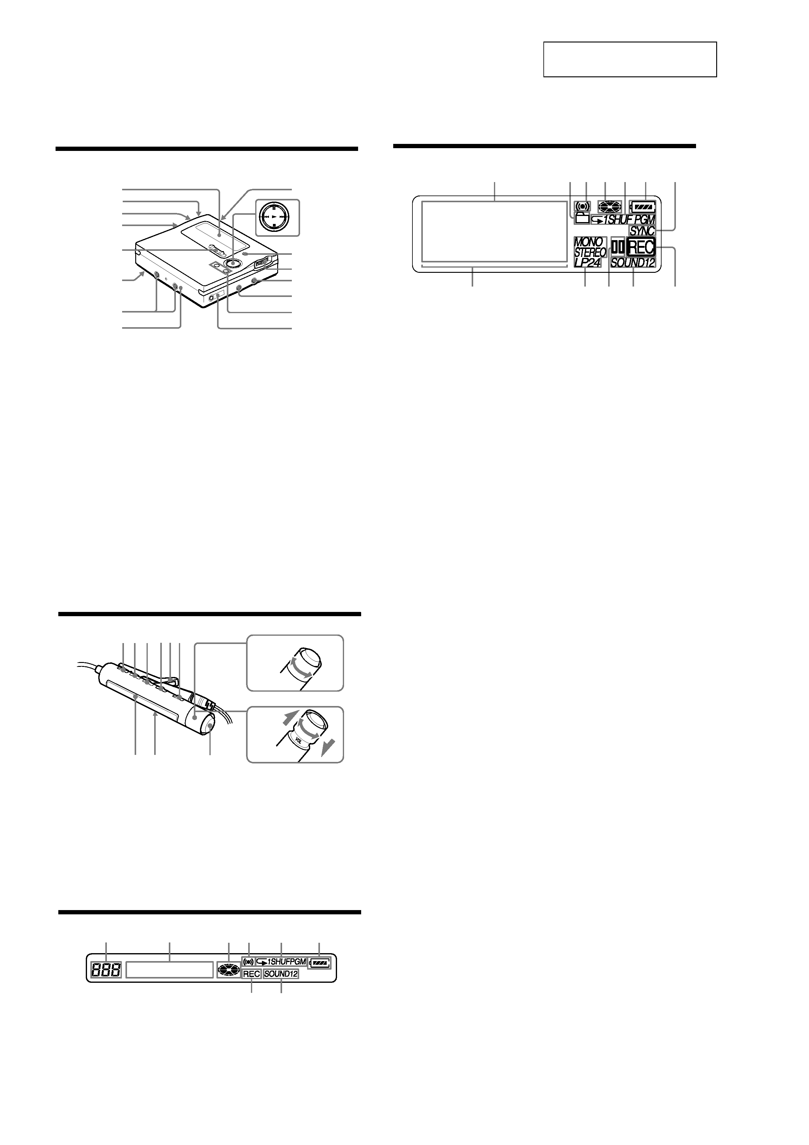
Looking at controls
See pages in ( ) for more details.
The recorder
A Display window (11) (32) (45) (55)
(70)
B T MARK button (39) (56) (67)
C END SEARCH button (23) (31) (60)
D Battery compartment (19)
E REC (record) switch (23) (28)
F HOLD switch (at the rear) (20) (74)
G Terminals for attaching dry battery
case (20)
H DC IN 3V jack (19) (22)
I OPEN button (21)
J N (play/enter) button (23) (25) (56)
X (pause) button (23) (25) (36) (43)
(56)
./> (REW/FF) buttons (23)
(25) (32) (43) (56) (68)
x (stop)/CHG button (21) (23) (25)
(40) (48) (56)
K GROUP/CANCEL button (31) (43)
(56) (61)
L Jog dial (MENU/ENTER) (11) (29)
(40) (42) (56) (70)
M LINE IN (OPT) jack (22) (28)
N MIC (PLUG IN POWER) jack (34)
The MIC (PLUG IN POWER) jack
has a tactile dot.
O VOL +/ button (25) (56)
The VOL +/ button has a tactile dot.
P i (headphones/earphones)/LINE
OUT jack (20) (40) (53)
1
2
3
4
5
6
qg
qh
qf
qs
qa
qd
9
8
7
J
9
The display window of the recorder
A Character information display (11)
(37) (45) (55) (70)
Displays the disc and track names,
date, error messages, track numbers,
etc.
B Group indication (31) (43) (57)
C Alarm indication (70)
D Disc indication (32) (45) (55) (70)
Shows that the disc is rotating for
recording, playing or editing an MD.
E Play mode indication (45)
Shows the play mode (shuffle play,
program play, repeat play, etc.) of the
MD.
F Battery indication (19) (75)
Shows approximate battery condition.
G SYNC (synchro-recording) indication
(32)
H Level meter (36) (45)
I STEREO (SP stereo), LP2 (LP2
stereo), LP4 (LP4 stereo), MONO
(monaural) indication (29)
J Pause indication
K Sound indication (48)
Lights up when Digital Sound Preset
is on.
L REC indication (23) (36)
Lights up while recording. When
flashing, the recorder is in record
standby mode.
13
24
5
6
7
qs
qa
q;
9
8
10
The headphones/earphones with a remote control
A DISPLAY button (31) (38) (42) (53)
(58) (71)
B PLAYMODE button (44) (47) (58)
C RPT/ENT (repeat/enter) button (47)
(49)
D SOUND button (49)
E Clip
F X (pause) button (25) (42) (58) (61)
G Control (./N>) (25) (31)
(42) (49) (58) (71)
N> : play, AMS, FF
. : REW
Turn or turn and hold to play, fast
forward, rewind, etc.
H Control (VOL +/) (25) (58)
Pull and turn to adjust the volume.
I Display window (38) (47) (71)
J HOLD switch (20) (74)
K x (stop) button1) (25) (31) (42) (58)
(71)
1)May be used as the "Enter" button, depending
on the function.
The display window of the remote control
A Track number display (38) (47) (71)
B Character information display (38)
(47) (53) (71)
C Disc indication (38) (47) (71)
D Alarm indication (71)
E Play mode indication (47)
F Battery level indication (38) (47) (71)
G REC indication (23) (38)
H SOUND indication (49)
+
A B C DE
K
F
IJ
G
H
F
H
G
A
BC
D
E
5
MZ-R909
· This set can be disassembled in the order shown below.
3-1.
DISASSEMBLY FLOW
SECTION 3
DISASSEMBLY
Note: Follow the disassembly procedure in the numerical order given.
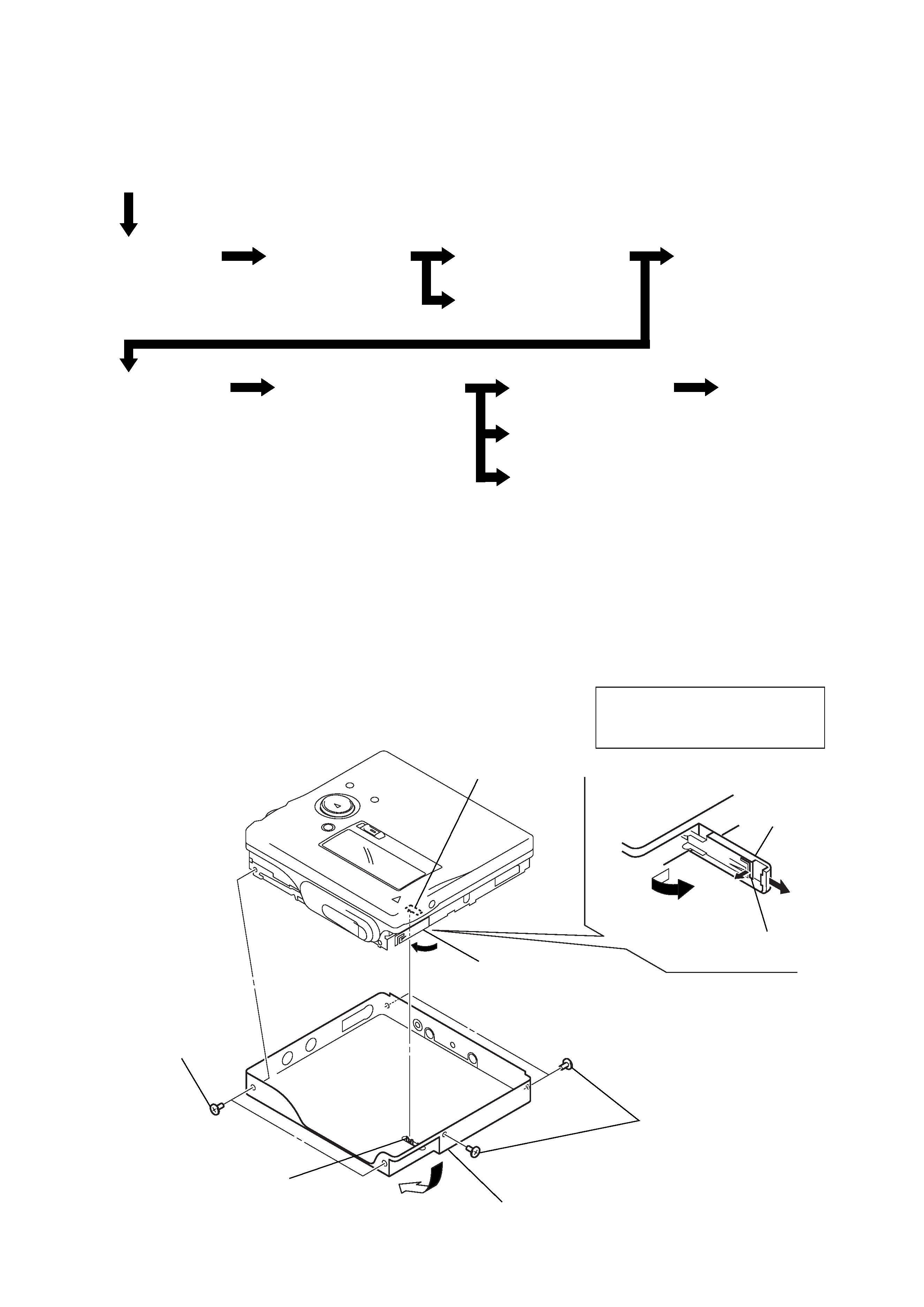
3-2.
PANEL ASSY, BOTTOM
3-2. Panel Assy,
Bottom
3-3. Panel Assy,
Upper Section
Set
3-4. "LCD Module",
"Panel Assy, Upper"
3-6. "Case Assy, Battery",
"Main Board"
3-8. "MD Mechanism Deck
(MT-MZR909-171)",
"Chassis Assy, Set"
3-7. Strip,
Ornamental
3-5. Main Board Assy
3-9. Service Assy, OP
(LCX-4R)
3-10. Holder Assy
3-11. Motor, DC (Sled) (M602)
3-12. "Motor, DC (Spindle) (M601)",
"Motor, DC (Over Write Head Up/Down)
(M603)"
S801
1
Open the lid,
battery case.
4
Close the battery
terminal (plus).
6
Remove the "panel assy, bottom"
in the direction of the arrow A.
knob (hold)
3
lid,
battery case
2
claw
A
5
two ES lock screws
5
three ES lock screws
Note: On installation,
adjust the position of both
switch (S801) and knobs(hold).