SERVICE MANUAL
PORTABLE MINIDISC RECORDER
US Model
AEP Model
UK Model
E Model
Australian Model
Chinese Model
Tourist Model
SPECIFICATIONS
MZ-NH1
Audio playing system
MiniDisc digital audio system
Laser diode properties
Material: GaAlAs
Wavelength:
= 790 nm
Emission duration: continuous
Laser output: less than 44.6
µW
(This output is the value measured at a distance
of 200 mm from the lens surface on the optical
pick-up block with 7 mm aperture.)
Recording and playback time (Refer
to page 94 for details)
When using HMD1G (1GB disc):
Maximum 34 hours in Hi-LP stereo
When using MDW-80 in Hi-MD mode:
Maximum 10 hours and 10 min. in Hi-LP
stereo
When using MDW-80 in MD mode:
Maximum 160 min. in monaural
Maximum 320 min. in LP4 stereo
Revolutions
350 rpm to 3,600 rpm (CLV)
Error correction
Hi-MD:
LDC (Long Distance Code)/BIS (Burst
Indicator Subcode)
MD:
ACIRC (Advanced Cross Interleave Reed
Solomon Code)
Sampling frequency
44.1 kHz
Sampling rate converter
Input: 32 kHz/44.1 kHz/48 kHz
Coding
Hi-MD:
Linear PCM (44.1 kHz/16 bit) -- PCM
ATRAC3plus (Adaptive TRansform
Acoustic Coding 3 plus)
MD:
ATRAC
ATRAC3 -- LP2/LP4
Modulation system
Hi-MD:
1-7RLL (Run Length Limited)/PRML
(Partial Response Maximum Likelihood)
MD:
EFM (Eight to Fourteen Modulation)
Frequency response
20 to 20,000 Hz
± 3 dB
Inputs1)
MIC: stereo mini-jack
(minimum input level 0.13 mV)
Line in:
stereo mini-jack for analog input
(minimum input level 49 mV)
optical (digital) mini-jack for optical
(digital) input
Outputs
i/LINE OUT2): stereo mini-jack (dedicated
emote control jack)/194 mV (10 k
)
Maximum output (DC)2)
Headphones:
5 mW + 5 mW (16
)
Power requirements
Sony AC Power Adaptor connected at the DC
IN 6V jack:
120 V AC, 60 Hz (Models for USA, Canada,
Mexico, and Taiwan)
240 V AC, 50 Hz (Model for Australia)
230 V AC, 50 Hz (Models for U.K. and
Hong Kong)
220 V AC, 50 Hz (Model for China)
100 - 240 V AC, 50/60 Hz (Other models)
The recorder:
Lithium-ion rechargeable battery
LIP-4WM, 3.7 V, 370 mAh, Li-ion
Battery charging stand:
AC power adaptor DC 6V
Operating temperature
+5
° C (+41° F) to +35° C (+95° F)
Hi-MD mode (When using a 60/74/80-
minute standard disc)
(Unit: approx.hours)(JEITA)
Battery life 4)
Hi-MD mode (When using a 1GB Hi-
MD disc)
(Unit: approx.hours)(JEITA3))
When
Linear
PCM
Hi-SP
Hi-LP
Recording
continuously
68.5
9.5
Playing
continuously
10
15.5
18
When
Linear
PCM
Hi-SP
Hi-LP
Recording
continuously
58
9
Playing
continuously
8
14.5
17.5
Ver 1.1 2004.09
US and foreign patents licensed from Dolby
Laboratories.
Model Name Using Similar Mechanism
NEW
MD Mechanism Type
MT-MZNH1-181
Optical Pick-up Name
ABX-U
9-879-075-02
2004I05-1
© 2004.09
Sony Corporation
Personal Audio Company
Published by Sony Engineering Corporation
Continued on next page
· SonicStage and SonicStage logo are trademarks or registered trademarks of Sony Corporation.
·MD Simple Burner, OpenMG, "MagicGate", "MagicGate Memory Stick", "Memory Stick", Hi-
MD, Net MD, ATRAC, ATRAC3, ATRAC3plus and their logos are trademarks of Sony Corporation.
·Microsoft, Windows, Windows NT and Windows Media are trademarks or registered trademarks
of Microsoft Corporation in the United States and/or other countries.
· IBM and PC/AT are registered trademarks of International Business Machines Corporation.
·Macintosh is a trademark of Apple Computer, Inc. in the United States and/or other countries.
·Pentium is a trademark or registered trademark of Intel Corporation.
· All other trademarks and registered trademarks are trademarks or registered trademarks of their
respective holders.

2
MZ-NH1
Dimensions
Approx. 81.7
× 76.1 × 14.8 mm (w/h/d)
(31/4
× 3 × 19/32 in.) (excluding projecting parts
and controls)
Mass
Approx. 97 g (3.4 oz) (the recorder only)
Approx. 107 g (3.8 oz) (including the
rechargeable battery)
1)The LINE IN (OPT) jack is used to connect
either a digital (optical) cable or a line
(analog) cable.
2)The i/LINE OUT jack connects either
headphones/earphones or a line cable.
Design and specifications are subject to change
without notice.
Your dealer may not handle some of the above
listed accessories. Please ask the dealer for
detailed information about the accessories in
your country.
When using optional headphones, use only
headphones/earphones with stereo mini
plugs. You cannot use headphones/
earphones with micro plugs.
4) When using a 100% fully charged lithium-ion
rechargeable battery
3) Measured in accordance with the JEITA
(Japan Electronics and Information
Technology Industries Association) standard.
On power sources
Use house current or rechargeable battery.
For use in your house: For the supplied battery
charging stand, use the AC power adaptor
supplied with this recorder. Do not use any
other AC power adaptor since it may cause the
recorder to malfunction.
Polarity of the plug
MD mode
(Unit: approx.hours)(JEITA)
When
SP
Stereo
LP2
Stereo
LP4
Stereo
Recording
continuously
810
10.5
Playing
continuously
14.5
17
18.5

3
MZ-NH1
TABLE OF CONTENTS
1.
SERVICING NOTES ............................................... 4
2.
GENERAL ................................................................... 5
3.
DISASSEMBLY
3-1.
Disassembly Flow ...........................................................
7
3-2.
Bottom Panel Sub Assy ...................................................
7
3-3.
MAIN Board ....................................................................
8
3-4.
Upper Panel Sub Assy .....................................................
8
3-5.
Control Ornament Block .................................................
9
3-6.
Mechanism Deck Assy (MT-MZNH1-181) ....................
9
3-7.
Gear (SA), Gear (SB) ...................................................... 10
3-8.
Op Service Assy .............................................................. 10
3-9.
DC SSM18D/C-NP Motor (Spindle) (M701),
DC SSM21A/C-NP Motor (Sled) (M702),
DC Motor Unit (Over Write Head Up/Down) (M703) ... 11
3-10. Holder Assy ..................................................................... 11
4.
TEST MODE ............................................................... 12
5.
ELECTRICAL ADJUSTMENT ............................. 16
6.
DIAGRAMS
6-1.
Block Diagram MD SERVO Section ......................... 21
6-2.
Block Diagram AUDIO Section ................................. 22
6-3.
Block Diagram POWER SUPPLY Section ................ 23
6-4.
Schematic Diagram MAIN Section (1/9) ................... 25
6-5.
Schematic Diagram MAIN Section (2/9) ................... 26
6-6.
Schematic Diagram MAIN Section (3/9) ................... 27
6-7.
Schematic Diagram MAIN Section (4/9) ................... 28
6-8.
Schematic Diagram MAIN Section (5/9) ................... 29
6-9.
Schematic Diagram MAIN Section (6/9) ................... 30
6-10. Schematic Diagram MAIN Section (7/9) ................... 31
6-11. Schematic Diagram MAIN Section (8/9) ................... 32
6-12. Schematic Diagram MAIN Section (9/9) ................... 33
6-13. Printed Wiring Board MAIN Section (1/2) ................ 34
6-14. Printed Wiring Board MAIN Section (2/2) ................ 35
7.
EXPLODED VIEWS
7-1.
PANEL SECTION ........................................................... 49
7-2.
MAIN SECTION ............................................................ 50
7-3.
MECHANISM DECK SECTION ................................... 51
8.
ELECTRICAL PARTS LIST ................................ 52
Notes on chip component replacement
· Never reuse a disconnected chip component.
· Notice that the minus side of a tantalum capacitor may be
damaged by heat.
Flexible Circuit Board Repairing
· Keep the temperature of the soldering iron around 270 °C
during repairing.
· Do not touch the soldering iron on the same conductor of the
circuit board (within 3 times).
· Be careful not to apply force on the conductor when soldering
or unsoldering.
CAUTION
Use of controls or adjustments or performance of procedures
other than those specified herein may result in hazardous radiation
exposure.
SAFETY-RELATED COMPONENT WARNING!!
COMPONENTS IDENTIFIED BY MARK 0 OR DOTTED LINE
WITH MARK 0 ON THE SCHEMATIC DIAGRAMS AND IN
THE PARTS LIST ARE CRITICAL TO SAFE OPERATION.
REPLACE THESE COMPONENTS WITH SONY PARTS WHOSE
PART NUMBERS APPEAR AS SHOWN IN THIS MANUAL OR
IN SUPPLEMENTS PUBLISHED BY SONY.
4
MZ-NH1
The laser diode in the optical pick-up block may suffer electrostatic
break-down because of the potential difference generated by the
charged electrostatic load, etc. on clothing and the human body.
During repair, pay attention to electrostatic break-down and also
use the procedure in the printed matter which is included in the
repair parts.
The flexible board is easily damaged and should be handled with
care.
NOTES ON LASER DIODE EMISSION CHECK
The laser beam on this model is concentrated so as to be focused on
the disc reflective surface by the objective lens in the optical pick-
up block. Therefore, when checking the laser diode emission,
observe from more than 30 cm away from the objective lens.
NOTES ON HANDLING THE OPTICAL PICK-UP
BLOCK OR BASE UNIT
SECTION 1
SERVICING NOTES
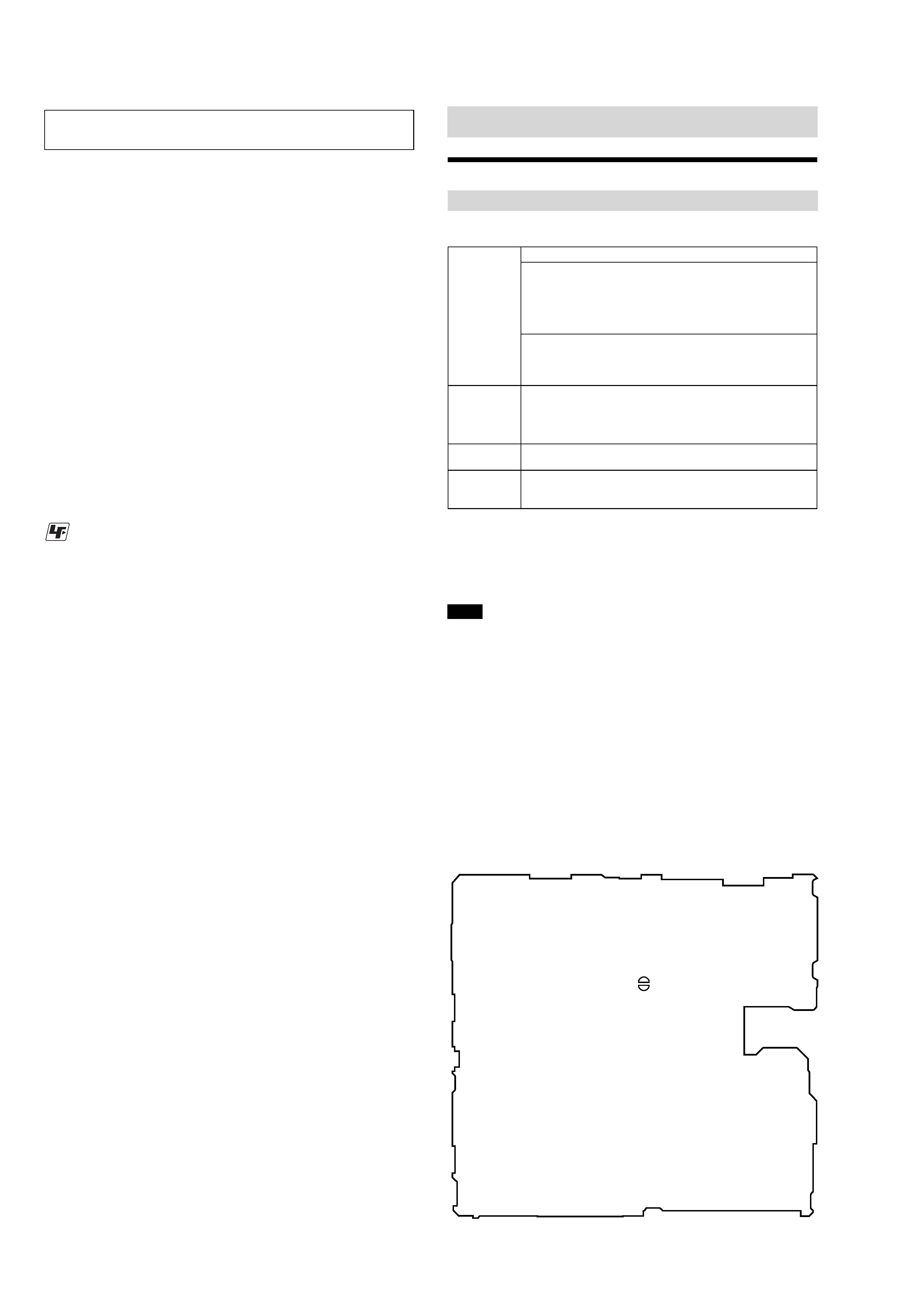
MAIN Board (Conductor Side)
SL894
(OPEN/CLOSE)
Installing
Providing the required system environment
The following system environment is required in order to use the SonicStage/MD Simple
Burner software for the MD Walkman.
This software is not supported by the following environments:
OSs other than the indicated above
Personally constructed PCs or operating systems
An environment that is an upgrade of the original manufacturer-installed operating system
Multi-boot environment
Multi-monitor environment
Macintosh
We do not ensure trouble-free operation on all computers that satisfy the system requirements.
The NTFS format of Windows XP/Windows 2000 Professional can be used only with the standard
(factory) settings.
We do not ensure trouble-free operation of the system suspend, sleep, or hibernation function on all
computers.
For Windows 2000 Professional users, install Service Pack 3 or later version before using the
software.
System requirements
Computer
IBM PC/AT or Compatible
CPU: Pentium II 400 MHz or higher (Pentium III 450 MHz or higher
is recommended.)
Hard disk drive space: 200 MB or more (1.5 GB or more is
recommended) (The amount space will vary according to Windows
version and the number of music files stored on the hard disk.)
RAM: 64 MB or more (128 MB or more is recommended)
Others
CD drive (capable of digital playback by WDM)
Sound Board
USB port (supports USB (previously USB 1.1))
Operating
System
Factory installed:
Windows XP Media Center Edition 2004/Windows XP Media Center
Edition/Windows XP Professional/Windows XP Home Edition/
Windows 2000 Professional/Windows Millennium Edition/Windows
98 Second Edition
Display
High Color (16bit) or higher, 800
× 600 dots or better (1024 × 768 dots
or better is recommended)
Others
Internet access: for Web registration, EMD services and CDDB
Windows Media Player (version 7.0 or higher) installed for playing
WMA files
Notes
UNLEADED SOLDER
Boards requiring use of unleaded solder are printed with the lead-
free mark (LF) indicating the solder contains no lead.
(Caution: Some printed circuit boards may not come printed with
the lead free mark due to their particular size)
: LEAD FREE MARK
Unleaded solder has the following characteristics.
· Unleaded solder melts at a temperature about 40 °C higher
than ordinary solder.
Ordinary soldering irons can be used but the iron tip has to be
applied to the solder joint for a slightly longer time.
Soldering irons using a temperature regulator should be set to
about 350
°C.
Caution: The printed pattern (copper foil) may peel away if
the heated tip is applied for too long, so be careful!
· Strong viscosity
Unleaded solder is more viscou-s (sticky, less prone to flow)
than ordinary solder so use caution not to let solder bridges
occur such as on IC pins, etc.
· Usable with ordinary solder
It is best to use only unleaded solder but unleaded solder may
also be added to ordinary solder.
OPERATION CHECK WHEN THE MAIN BOARD IS
REMOVED
In making an operation check with the MAIN Board removed from
the set, short the SL894 (OPEN/CLOSE) of the MAIN Board with
the solder before starting the operation check.
Note: Be sure to remove the solder used for shortcircuit after the repaire
completed.
5
MZ-NH1
SECTION 2
GENERAL
This section is extracted from
instruction manual.
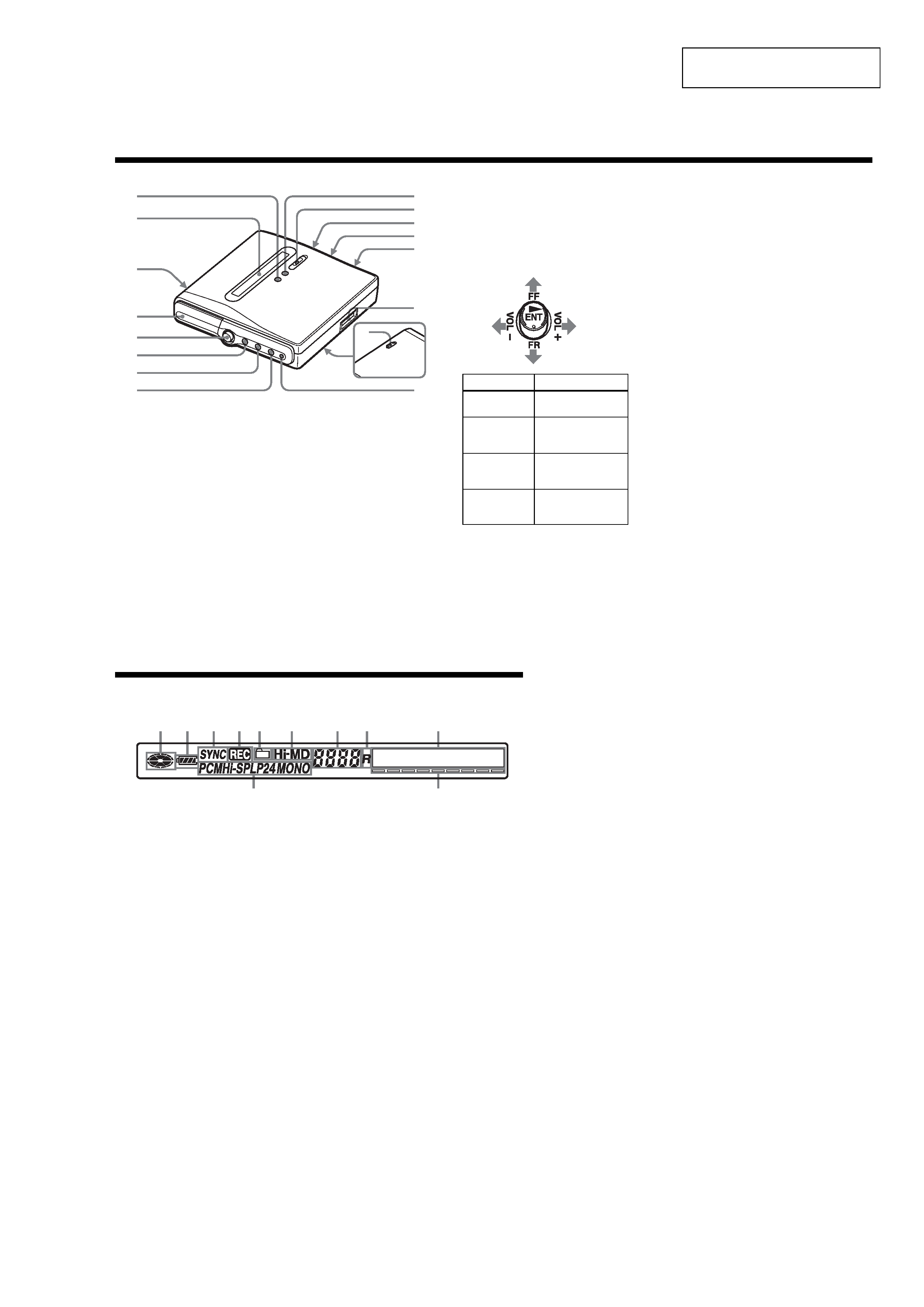
Looking at controls
The recorder
A x (stop) · CANCEL button
B Display window
C OPEN switch
D Battery compartment
E 5-way control key
F MENU button
G GROUP button
H T MARK button
I X (pause) button
J zREC (record) switch/lamp
K LINE IN (OPT) jack
L MIC (PLUG IN POWER) jack
There is a tactile dot beside the MIC
(PLUG IN POWER) jack.
M i (headphones/earphones)/LINE
OUT jack
N USB connecting jack
1
2
3
4
8
5
6
7
9
0
qa
qs
qd
qf
qg
qh
Operation
Function
Press NENT
1)
play, enter
Press towards
FR
find the beginning
of the previous
track, rewind
Press towards
FF
find the beginning
of the next track,
fast forward
Press towards
VOL +1) or
VOL .
volume
1) There are tactile dots beside the
N ENT and VOL + buttons.
O HOLD switch (at the rear)
Slide the switch in the direction of the
arrow to disable the buttons on the
recorder. To prevent the buttons from
being accidentally operated when you
carry the recorder, use this function.
P CHG (Charge) lamp
The display window of the recorder
A Disc indication
Shows that the disc is rotating for
recording or playing.
B Battery indication
Shows the approximate remaining
battery power. If the rechargeable
battery is weak, the indication
becomes empty and starts flashing.
C SYNC (synchro-recording) indication
D REC indication
Lights up during recording or file
transfers from the computer. When
flashing, the recorder is in record
standby mode.
E Group indication
F Hi-MD/MD indication
"Hi-MD" lights up when the
operation mode of the recorder is in
Hi-MD mode and "MD" lights up
when the operation mode is in MD
mode.
G Track number display
H "R" (Remain) indication
Lights up when remaining recordable
time is displayed.
I Character information display
Displays the menu items, date, error
messages, etc.
J Track mode (PCM, Hi-SP, Hi-LP, SP,
LP2, LP4, MONO) indication
K Level meter
12
3
4 5
6
7
8
9
qa
0