SERVICE MANUAL
PORTABLE MINIDISC RECORDER
US Model
Canadian Model
AEP Model
UK Model
E Model
Australian Model
Chinese Model
Tourist Model
SPECIFICATIONS
MZ-N707
US and foreign patents licensed from Dolby
Laboratories.
Continued on next page
Model Name Using Similar Mechanism
NEW
Mechanism Type
MT-MZN707-177
Optical Pick-up Name
LCX-5R
Ver 1.2 2003. 08
9-873-458-03
Sony Corporation
2003H05-1
Personal Audio Company
C
2003.08
Published by Sony Engineering Corporation
· OpenMG, "MagicGate", "MagicGate Memory Stick", "Memory Stick",
VAIO,MusicClip and their logos are trademarks of Sony Corporation.
· "WALKMAN" is a trademark of Sony Corporation.
· Microsoft,Windows,Windows NT and Windows Media are trademarks
or registered trademarks of Microsoft Corporation in the United States
and/or other countries.
· IBM and PC/AT are registered trademarks of International Business
Machines Corporation.
· Macintosh is a trademark of Apple Computer,Inc.in the United States
and/or other countries.
· All other trademarks are trademarks of their respective owners. TM and
® marks are omitted in this manual.
MD Recorder
Audio playing system
MiniDisc digital audio system
Laser diode properties
Material: GaAlAs MQW
Wavelength:
= 790 nm
Emission duration: continuous
Laser output: less than 44.6
µW
(This output is the value measured at a distance
of 200 mm from the lens surface on the optical
pick-up block with 7 mm aperture.)
Recording and playback time
When using MDW-80
Maximum 160 min. in monaural
Maximum 320 min. in stereo
Revolutions
Approx. 380 rpm to 2,700 rpm (CLV)
Error correction
ACIRC (Advanced Cross Interleave Reed
Solomon Code)
Sampling frequency
44.1 kHz
Sampling rate converter
Input: 32 kHz/44.1 kHz/48 kHz
Coding
ATRAC (Adaptive TRansform Acoustic
Coding)
ATRAC3 -- LP2
ATRAC3 -- LP4

2
MZ-N707
Modulation system
EFM (Eight to Fourteen Modulation)
Number of channels
2 stereo channels
1 monaural channel
Frequency response
20 to 20,000 Hz
± 3 dB
Wow and Flutter
Below measurable limit
Inputs
Microphone: stereo mini-jack, minimum input
level 0.35 mV
Line in: stereo mini-jack, minimum input level
49 mV
Optical (Digital) in: optical (digital) mini-jack
Output
i: stereo mini-jack, maximum output level
5mW+5mW, load impedance 16 ohm (except US model)
5mW+5mW, load impedance 24 ohm (US model)
General
Power requirements
Sony AC Power Adaptor connected at the DC
IN 3 V jack (country model in parentheses):
Nickel Cadmium rechargeable battery NC-
WMAA (supplied)
LR6 (size AA) alkaline battery (not supplied)
Dimensions
Approx. 81
× 74.4 × 27.7 mm (w/h/d) (31/4 × 3
× 11/8 in.) without projections.
Mass
Approx. 116 g (4.1 oz) the recorder only
Supplied accessories
NC-WMAA Nickel Cadmium rechargeable battery (1)
AC power adaptor (1)
Headphones/earphones (1)
Remote control (1)
Battery charging stand (1)
Optical cable (1)
USB cable (1)
CD-ROM (1)*
Battery carrying case (1)
Carrying pouch (1)
Carrying case with a belt clip (1)
(E, Australian, Chinese and Tourist models)
(Canadian, AEP and UK models)
Car connecting pack (1) (US and Canadian models)
Blank Minidisc (1) (US and Canadian models)
Car battery cord (1) (US and Canadian models)
Carrying case with Velcro strips (1)
(US and Canadian models)
AC plug adaptor (1) (Tourist model)
Spiral tube (1) (US and Canadian models)
Design and specifications are subject to change
without notice.
Do not play a CD-ROM on an audio CD player.
Battery life1)
When recording2)
(Unit: approx.hours)(JEITA3))
1) The battery life may be shorter due to operating
conditions, the temperature of the location, and
varieties of batteries.
2) When you record, use a fully charged
rechargeable battery. Recording time may
differ according to the alkaline batteries.
3) Measured in accordance with the JEITA (Japan
Electronics and Information Technology
Industries Association) standard.
Batteries
SP
Stereo
LP2
Stereo
LP4
Stereo
NC-WMAA
Nickel
Cadmium
rechargeable
battery4)
4) When using a 100% fully charged rechargeable
battery.
46
7.5
LR6 (SG)
Sony alkaline
dry battery5)
5) When using a Sony LR6 (SG) "STAMINA"
alkaline dry battery (produced in Japan).
913
16
When playing
(Unit: approx.hours)(JEITA1))
Batteries
SP
Stereo
LP2
Stereo
LP4
Stereo
NC-WMAA
Nickel
Cadmium
rechargeable
battery2)
15
16
20
LR6 (SG)
Sony alkaline
dry battery3)
42
48
56
1) Measured in accordance with the JEITA
(Japan Electronics and Information
Technology Industries Association) standard.
2) When using a 100% fully charged
rechargeable battery.
3) When using a Sony LR6 (SG) "STAMINA"
alkaline dry battery (produced in Japan).
120 V AC, 60 Hz (USA, Canada and
Taiwan)
230 V AC, 50/60 Hz (Continental Europe)
240 V AC, 50 Hz (Australia)
220 V AC, 50 Hz (China)
230 - 240 V AC, 50 Hz (U.K. and Hong
Kong)
110/220 V AC, 60 Hz (Korea)
100 - 240 V AC, 50/60 Hz (Other countries)
ATTENTION AU COMPOSANT AYANT RAPPORT
À LA SÉCURITÉ!
LES COMPOSANTS IDENTIFIÉS PAR UNE MARQUE 0
SUR LES DIAGRAMMES SCHÉMATIQUES ET LA LISTE
DES PIÈCES SONT CRITIQUES POUR LA SÉCURITÉ
DE FONCTIONNEMENT. NE REMPLACER CES COM-
POSANTS QUE PAR DES PIÈCES SONY DONT LES
NUMÉROS SONT DONNÉS DANS CE MANUEL OU
DANS LES SUPPLÉMENTS PUBLIÉS PAR SONY.
SAFETY-RELATED COMPONENT WARNING!!
COMPONENTS IDENTIFIED BY MARK 0 OR DOTTED
LINE WITH MARK 0 ON THE SCHEMATIC DIAGRAMS
AND IN THE PARTS LIST ARE CRITICAL TO SAFE
OPERATION. REPLACE THESE COMPONENTS WITH
SONY PARTS WHOSE PART NUMBERS APPEAR AS
SHOWN IN THIS MANUAL OR IN SUPPLEMENTS PUB-
LISHED BY SONY.
Ver 1.1
3
MZ-N707
On power sources
· Use house current, Nickel Cadmium
rechargeable battery, LR6 (SG) battery, or car
battery.
· For use in your house: Use the AC power
adaptor supplied with this recorder. Do not
use any other AC power adaptor since it may
cause the recorder to malfunction.
kh AC
d
Polarity of the
plug
TABLE OF CONTENTS
1.
SERVICING NOTES ............................................... 4
2.
GENERAL ................................................................... 5
3.
DISASSEMBLY
3-1. Disassembly Flow ...........................................................
6
3-2. Case (Lower) ...................................................................
7
3-3. Upper Panel Section ........................................................
7
3-4. LCD Module, Upper Panel Sub Assy .............................
8
3-5. Mechanism Deck (MT-MZN707-177) ...........................
8
3-6. Set Chassis (5192) Assy ..................................................
9
3-7. MAIN Board ...................................................................
9
3-8. OP Service Assy (LCX-5R) ............................................ 10
3-9. Holder Assy ..................................................................... 11
3-10. DC Motor (Sled) (M602) ................................................ 11
3-11. DC SSM18B Motor (Spindle) (M601),
DC Motor (Over Write Head Up/Down) (M603) .......... 12
4.
TEST MODE .............................................................. 13
5.
ELECTRICAL ADJUSTMENTS ......................... 19
6.
DIAGRAMS
6-1. Block Diagram SERVO/USB Section ...................... 32
6-2. Block Diagram AUDIO Section ............................... 33
6-3. Block Diagram DISPLAY/KEY CONTROL/
POWER SUPPLY Section ........................................... 34
6-4. Note for Printed Wiring Board and
Schematic Diagrams ....................................................... 35
6-5. Printed Wiring Board
MAIN Board (Component Side) ............................. 36
6-6. Printed Wiring Board
MAIN Board (Conductor Side) ............................... 37
6-7. Schematic Diagram MAIN Board (1/4) .................. 38
6-8. Schematic Diagram MAIN Board (2/4) .................. 39
6-9. Schematic Diagram MAIN Board (3/4) .................. 40
6-10. Schematic Diagram MAIN Board (4/4) .................. 41
6-11. IC Pin Function Description ........................................... 48
7.
EXPLODED VIEWS
7-1. Upper Panel, Case (Lower) Section ............................... 55
7-2. Chassis Section ............................................................... 56
7-3. MAIN Board Section ...................................................... 57
7-4. Mechanism Deck Section-1 (MT-MZN707-177) ........... 58
7-5. Mechanism Deck Section-2 (MT-MZN707-177) ........... 59
8.
ELECTRICAL PARTS LIST ............................... 60
CAUTION
Use of controls or adjustments or performance of procedures
other than those specified herein may result in hazardous ra-
diation exposure.
Notes on chip component replacement
·Never reuse a disconnected chip component.
· Notice that the minus side of a tantalum capacitor may be dam-
aged by heat.
Flexible Circuit Board Repairing
·Keep the temperature of the soldering iron around 270 °C dur-
ing repairing.
· Do not touch the soldering iron on the same conductor of the
circuit board (within 3 times).
· Be careful not to apply force on the conductor when soldering
or unsoldering.
UNLEADED SOLDER
Boards requiring use of unleaded solder are printed with the lead-
free mark (LF) indicating the solder contains no lead.
(Caution: Some printed circuit boards may not come printed with
the lead free mark due to their particular size)
: LEAD FREE MARK
Unleaded solder has the following characteristics.
· Unleaded solder melts at a temperature about 40 °C higher than
ordinary solder.
Ordinary soldering irons can be used but the iron tip has to be
applied to the solder joint for a slightly longer time.
Soldering irons using a temperature regulator should be set to
about 350 °C .
Caution: The printed pattern (copper foil) may peel away if the
heated tip is applied for too long, so be careful!
· Strong viscosity
Unleaded solder is more viscous (sticky, less prone to flow) than
ordinary solder so use caution not to let solder bridges occur
such as on IC pins, etc.
· Usable with ordinary solder
It is best to use only unleaded solder but unleaded solder may
also be added to ordinary solder.
4
MZ-N707
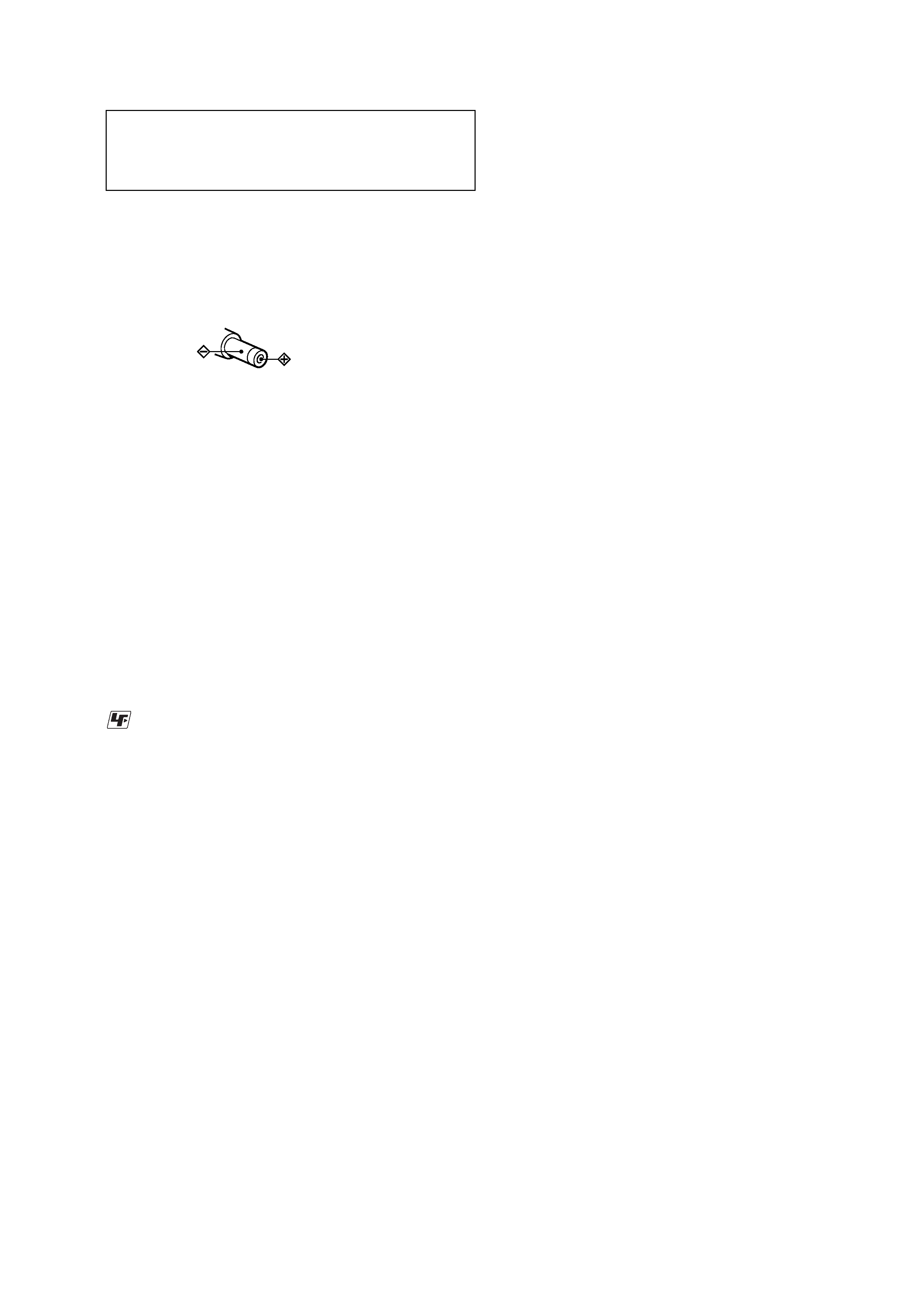
NOTES ON HANDLING THE OPTICAL PICK-UP
BLOCK OR BASE UNIT
The laser diode in the optical pick-up block may suffer electro-
static break-down because of the potential difference generated
by the charged electrostatic load, etc. on clothing and the human
body.
During repair, pay attention to electrostatic break-down and also
use the procedure in the printed matter which is included in the
repair parts.
The flexible board is easily damaged and should be handled with
care.
NOTES ON LASER DIODE EMISSION CHECK
Never look into the laser diode emission from right above when
checking it for adjustment. It is feared that you will lose your sight.
NOTES ON HANDLING THE OPTICAL PICK-UP BLOCK
(LCX-5R)
The laser diode in the optical pick-up block may suffer electro-
static break-down easily. When handling it, perform soldering
bridge to the laser-tap on the flexible board. Also perform mea-
sures against electrostatic break-down sufficiently before the op-
eration. The flexible board is easily damaged and should be handled
with care.
OPTICAL PICK-UP FLEXIBLE BOARD
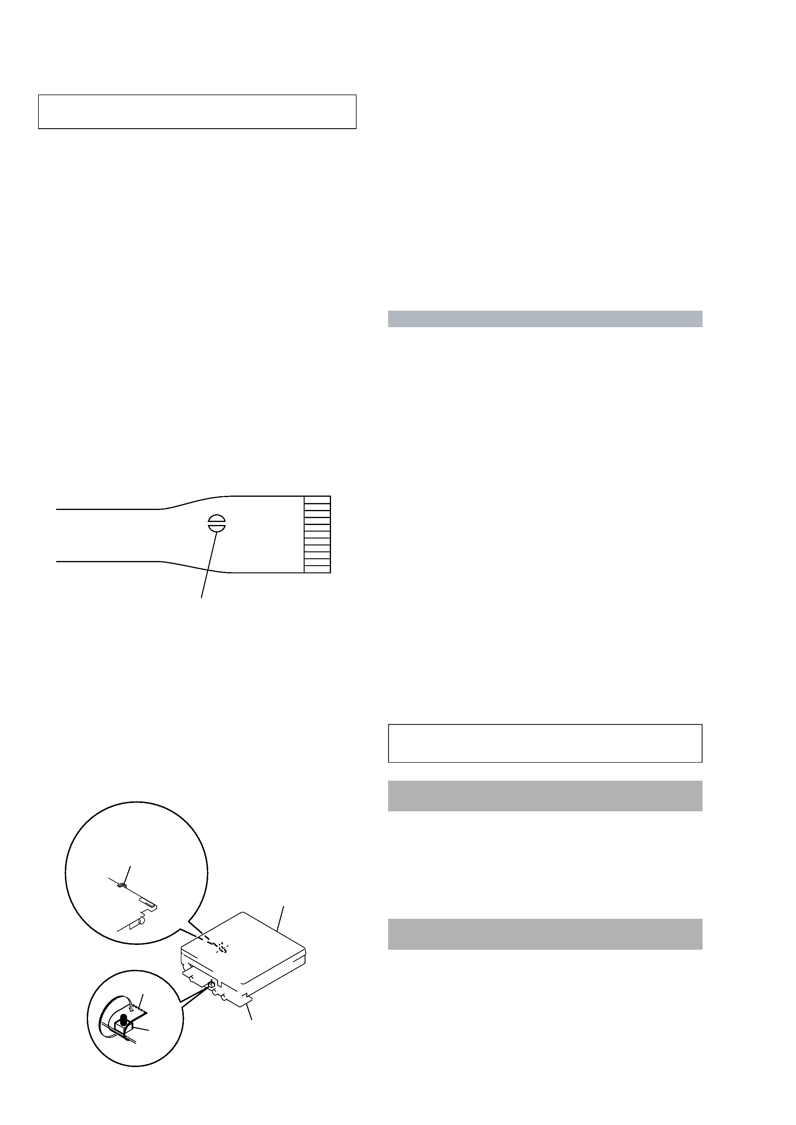
SECTION 1
SERVICING NOTES
· In performing the repair with the power supplied to the set, re-
moving the MAIN board causes the set to be disabled.
In such a case, fix a convex part of the open/close detect switch
(S806 on MAIN board) with a tape in advance.
Handle the FLEXIBLE board (over write head) with care, as it
has been soldered directly to the MAIN board.
In repairing the component side of MAIN board, connect the
FLEXIBLE board (over write head) and the MAIN board with
the lead wires in advance.
laser-tap
·The shipment data will be cleared when the NV is reset. There-
fore, change the NV adjusted values following the Change of
NV Adjusted Values immediately after the NV was reset. (See
page 19)
·The set having the microcomputer version 1.100 to 1.300 re-
quires the patch data in the nonvolatile memory (IC804) to be
rewritten using the application, when the MAIN board was re-
placed. (See page 29)
On the set having the microcomputer version 1.400 or later, re-
writing the patch data is unnecessary.
· Replacement of CXD2677-205GA (IC801) used in this set re-
quires a special tool.
System requirements
· IBM PC/AT or Compatible (The software does not run on Macintosh.)
CPU: MMXTM Pentium® 233 MHz or higher (Pentium® II 400 MHz or higher is
recommended.)
Hard disk drive space: 60 MB or more (The amount of necessary space depends on
the version of the Windows OS or the size of your audio files.)
RAM: 64 MB or higher (128 MB or higher is recommended for Windows® XP Home
Edition/Windows® XP Professional.)
CD-ROM drive (capable of digital playback by WDM)
Sound Board
USB port (supports USB 2.0 Full Speed (previously USB 1.1))
·Operating System: Windows® 98/Windows® 98 Second Edition/Windows® 2000
Professional/Windows® Me/Windows® XP Home Edition/Windows® XP
Professional (manufacturer installed)
The NTFS format of Windows® 2000 Professional, Windows® XP Home Edition, or
Windows® XP Professional (manufacturer-installed) is supported only when used
with the standard (factory) settings.
This software is not supported by the following environments.
Windows® 95, Windows® NT, or other versions of Windows® NT (such as Server)
An environment that is an upgrade of the original manufacturer-installed
operating system, as in the following examples:
Windows® 3.1/Windows® 95 t Windows® 98 (or Windows® 98 Second Edition/
Windows® Me)
Windows® Me/Windows® 2000 Professional t Windows® XP
Multi-boot environment with Windows® 2000 (or Windows® XP) and Windows®
98 (or Windows® 98 Second Edition/Windows® Me)
·Display: High (16bit) Color or more (800
× 480 dot or more)
· Internet access: for Web registration and EMD services
· Internet access: for software upgrades and CDDB2 use. (US and Canadian models)
·Windows Media Player (version 7.0 or higher) installed for playing WMA files.
Notes
·Trouble-free operation is not assured within a multiple-monitor environment.
·We do not assure trouble-free operation for all computers satisfying the system requirements.
· Trouble-free operation is not guaranteed following the self-conducted upgrade of home-built
PCs or operating systems.
·We do not assure trouble-free operation of the system suspend, sleep, or hibernation function on
all computers.
· For details, refer to "Net MD Help" of the online help.
Note
The optical digital output connector (on computers provided with one) may be disabled
during playback for the protection of copyrights.
Notes on using OpenMG Jukebox with Windows
2000/Windows XP
If your computer is Windows 2000 Professional, Windows XP Home Edition, or
Windows XP Professional, please be aware of the following before instaling OpenMG
Jukebox.
1 With Windows 2000 Professional, you must log on as "Administrators" (or with the
user name "Administrator") to install OpenMG Jukebox.
2 With Windows XP Home Edition or Windows XP Professional, you must log on
with user name "Computer Administrator" to install OpenMG Jubebox. To check
whether a user name has the attribute of "Computer Administrator" or not, go to
[Control Panel] - [User Account].
Notes on using OpenMG Jukebox with Windows XP/
Windows Me
If Windows XP/Windows Me is installed in your computer, and you perform the
"System Restore" function of the Windows "System Tools," the songs managed by
OpenMG Jukebox may become corrupted and rendered unplayable.
Therefore, before executing "System Restore," back up the songs using "OpenMG
Jukebox Backup Tool" first.
Then, after the "System Restore" function is finished, restore the songs using
"OpenMG Jukebox Backup Tool" to ensure the integrity and reliability of song
playback.
For more information about backup, refer to the online Help for OpenMG Jukebox.
Note
When songs become unplayable by executing "System Restore," an error dialog box may be
displayed. In this case, follow the displayed messages.
upper panel assy
MAIN board
tape
S806
FLEXIBLE board
(over write head)
Ver 1.2
5
MZ-N707
SECTION 2
GENERAL
This section is extracted from
instruction manual.
10
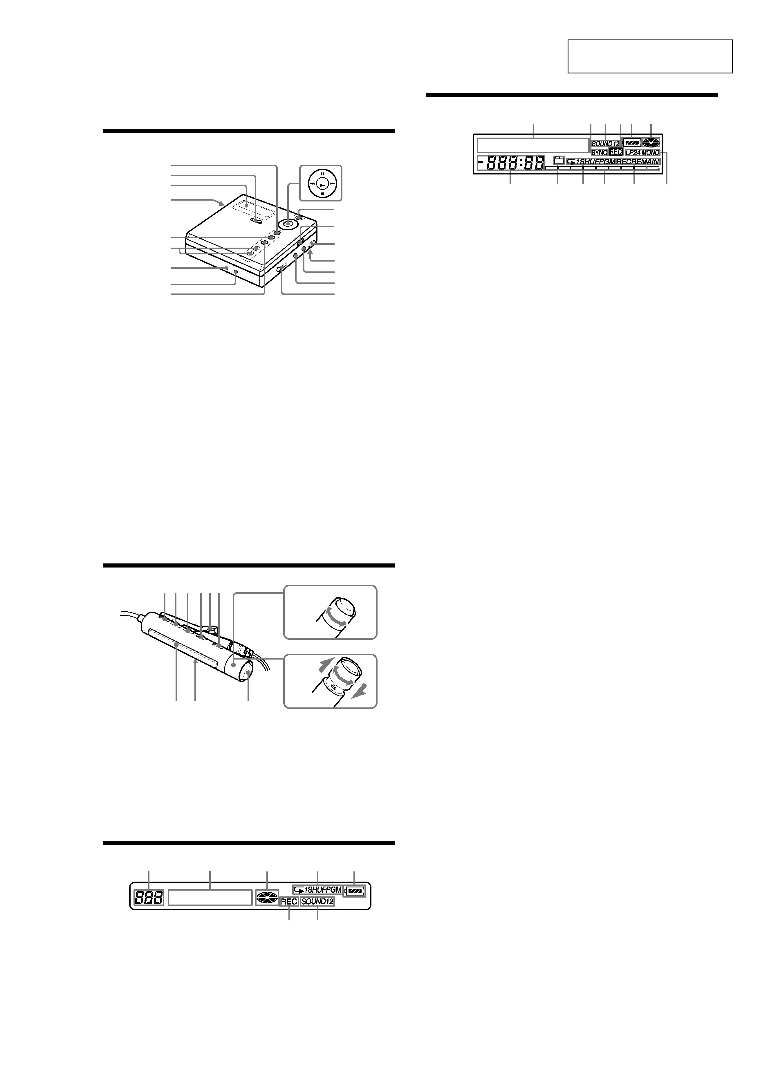
Looking at the controls
The recorder
A GROUP/CANCEL button
B REC (record) switch
C Display window
D OPEN button
E T MARK button
F VOL +/ button
The VOL + button has a tactile dot.
G Terminal for attaching the battery
charging stand
H DC IN 3V jack
I END SEARCH button
J 5 position control key
X (pause) button
./> (search/AMS) button
ENTER/N* (play) button
x (stop)/CHG (charge) button
*The N button has a tactile dot.
K MENU button
L HOLD switch
M USB connecting jack
N Battery compartment
O LINE IN (OPTICAL) jack
P MIC (PLUG IN POWER) jack
There is a tactile dot left side of the MIC
(PLUG IN POWER) jack.
Q i (headphones/earphones) jack
1
3
2
4
5
6
qg
qf
qh
qj
qa
qs
qd
7
8
9
J
ENTER
CH
G
11
The display window of the recorder
A Character information display
Displays the disc and track names,
error messages, track numbers, etc.
B SYNC (synchro-recording) indication
C Sound indication
D REC indication
Lights up while recording. When
flashing, the recorder is in record
standby mode.
E Battery level indication
Shows approximate battery condition.
F Disc indication
Shows that the disc is rotating for
recording, playing or editing an MD.
G Time display
H Group indication
Lights up when group mode is on.
I Play mode indication
Shows play mode of the MD.
J Level meter
Shows the volume of the MD being
played or recorded.
K REC REMAIN/REMAIN (remaining
time/tracks) indication
Lights up along with the remaining
time of the track, the remaining time
of the MD, or the remaining number
of tracks.
L Recording mode (LP2/LP4/MONO)
indication
13
24 5
6
7qs
qa
q;
9
8
12
The headphones/earphones with a remote control
A DISPLAY button
B PLAY MODE button
C RPT/ENT (repeat/enter) button
D SOUND button
E Clip
F X (pause) button
G Control (./N>)
N> : play, AMS, FF
. : REW, AMS
Turn or turn and hold to play, fast
forward, rewind, etc.
H Control (VOL +/)
Pull and turn to adjust the volume.
I Display window
J HOLD switch
K x (stop) button
May be used as the "Enter" button,
depending on the function.
The display window of the remote control
A Track number display
B Character information display
C Disc indication
D Play mode indication
E Battery level indication
F REC indication
G SOUND indication
+
A B C DE
K
F
IJ
G
H
.
N>
E
G
F
A
BC
D