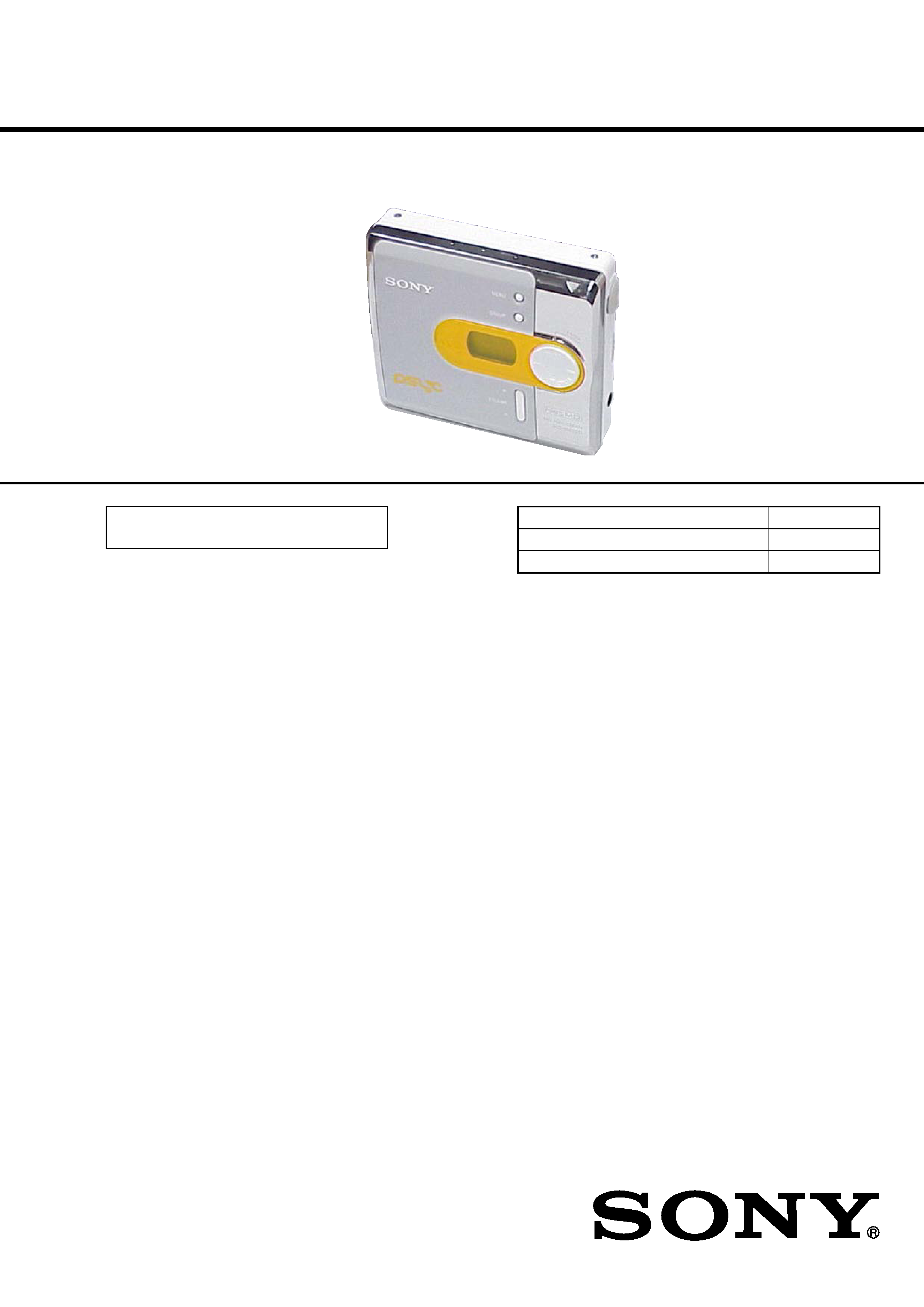
SERVICE MANUAL
PORTABLE MINIDISC PLAYER
US Model
Canadian Model
E Model
SPECIFICATIONS
MZ-N420D
US and foreign patents licensed from Dolby
Laboratories.
Continued on next page
Model Name Using Similar Mechanism
MZ-NE410
Mechanism Type
MT-MZN710-177
Optical Pick-up Name
LCX-5R
Ver 1.1 2004.10
9-877-707-02
Sony Corporation
2004J16-1
Personal Audio Company
© 2004.10
Published by Sony Engineering Corporation
· SonicStage, OpenMG and the OpenMG
logo, MagicGate, Memory Stick and the
MagicGate Memory Stick logo,
Memory Stick and the Memory Stick
logo, Net MD and the Net MD logo are
trademarks of Sony Corporation.
· Microsoft, Windows, Windows NT and
Windows Media are trademarks or
registered trademarks of Microsoft
Corporation in the United States and /or
other countries.
· IBM and PC/AT are registered
trademarks of International Business
Machines Corporation.
· Macintosh is a trademark of Apple
Computer, Inc. in the United States and/
or other countries.
· MMX and Pentium are trademarks or
registered trademarks of Intel
Corporation.
· All other trademarks and registered
trademarks are trademarks or registered
trademarks of their respective holders.
· TM and ® marks are omitted in this
manual.
Audio playing system
MiniDisc digital audio system
Laser diode properties
Material: GaAlAs
Wavelength:
= 790 nm
Emission duration: continuous
Laser output: less than 44.6
µW
(This output is the value measured at a distance
of 200 mm from the objective lens surface on
the optical pick-up block with 7 mm aperture.)
Recording and playback time (when
using MDW-80)
Maximum 160 min. in monaural
Maximum 320 min. in LP4 stereo
Revolutions
Approx. 380 rpm to 2,700 rpm
Error correction
ACIRC (Advanced Cross Interleave Reed
Solomon Code)
Sampling frequency
44.1 kHz
Coding
ATRAC (Adaptive TRansform Acoustic
Coding)
ATRAC3 -- LP2/LP4
2
MZ-N420D
SAFETY-RELATED COMPONENT WARNING!!
COMPONENTS IDENTIFIED BY MARK 0 OR DOTTED LINE
WITH MARK 0 ON THE SCHEMATIC DIAGRAMS AND IN THE
PARTS LIST ARE CRITICAL TO SAFE OPERATION. REPLACE
THESE COMPONENTS WITH SONY PARTS WHOSE PART NUM-
BERS APPEAR AS SHOWN IN THIS MANUAL OR IN SUPPLE-
MENTS PUBLISHED BY SONY.
ATTENTION AU COMPOSANT AYANT RAPPORT
À LA SÉCURITÉ!
LES COMPOSANTS IDENTIFÉS PAR UNE MARQUE 0 SUR LES
DIAGRAMMES SCHÉMATIQUES ET LA LISTE DES PIÈCES
SONT CRITIQUES POUR LA SÉCURITÉ DE FONCTIONNEMENT.
NE REMPLACER CES COMPOSANTS QUE PAR DES PIÈSES
SONY DONT LES NUMÉROS SONT DONNÉS DANS CE MANUEL
OU DANS LES SUPPÉMENTS PUBLIÉS PAR SONY.
Modulation system
EFM (Eight to Fourteen Modulation)
Number of channels
2 stereo channels
1 monaural channel
Frequency response
20 to 20,000 Hz
± 3 dB
Outputs
i: stereo mini-jack, maximum output level
5 mW + 5 mW, load impedance 24
(US)
5 mW + 5 mW, load impedance 16
(EXCEPT US)
General
Power requirements
One LR6 (size AA) alkaline battery (not
supplied)
Recommended temperature for
check-in/check-out
+5
° C (+41° F) or higher
Dimensions
s
Mas
Approx. 106 g (3.8 oz) the player only
Approx. 113.3 g (4.0 oz) the player only
Design and specifications are subject to change
without notice.
Supplied accessories
Headphones/earphones (1)
Dedicated USB cable (1)
CD-ROM (SonicStage Ver. 2.0 and
MD Simple Burner Ver. 2.0) (1)*
Battery life 1)
* Do not play a CD-ROM on an audio CD player.
1) When using a new Sony LR6 (size AA) "STAMINA" alkaline dry battery (produced in Japan).
When
SP Stereo
LP2 Stereo
LP4 Stereo
playing2)
2) Measured in accordance with the JEITA (Japan Electronics and Information Technology Industries
Association) standard.
Approx. 42 hours
Approx. 48 hours
Approx. 56 hours
transferring out audio
data from the computer3)
3) The numbers of tracks that can be checked out differs according to the computer's operating
environment.
75 tracks (of about
5 minutes each)
300 tracks (of about
5 minutes each)
600 tracks (of about
5 minutes each)
Recordable disc (US and Canadian models only) (1)
Approx. 81
× 28.9 × 74.4 mm (w/h/d) (31/4 ×
13/16
× 3 in.) without projections.
Left - hand model
Left - hand model
Approx. 81
× 30.7 × 74.4 mm (w/h/d) (31/4 ×
11/4
× 3 in.) without projections.
Right - hand model
Right - hand model
3
MZ-N420D
CAUTION
Use of controls or adjustments or performance of procedures
other than those specified herein may result in hazardous ra-
diation exposure.
Notes on chip component replacement
·Never reuse a disconnected chip component.
· Notice that the minus side of a tantalum capacitor may be dam-
aged by heat.
Flexible Circuit Board Repairing
·Keep the temperature of the soldering iron around 270 °C dur-
ing repairing.
· Do not touch the soldering iron on the same conductor of the
circuit board (within 3 times).
· Be careful not to apply force on the conductor when soldering
or unsoldering.
UNLEADED SOLDER
Boards requiring use of unleaded solder are printed with the lead-
free mark (LF) indicating the solder contains no lead.
(Caution: Some printed circuit boards may not come printed with
the lead free mark due to their particular size)
: LEAD FREE MARK
Unleaded solder has the following characteristics.
· Unleaded solder melts at a temperature about 40 °C higher than
ordinary solder.
Ordinary soldering irons can be used but the iron tip has to be
applied to the solder joint for a slightly longer time.
Soldering irons using a temperature regulator should be set to
about 350 °C .
Caution: The printed pattern (copper foil) may peel away if the
heated tip is applied for too long, so be careful!
· Strong viscosity
Unleaded solder is more viscous (sticky, less prone to flow) than
ordinary solder so use caution not to let solder bridges occur
such as on IC pins, etc.
· Usable with ordinary solder
It is best to use only unleaded solder but unleaded solder may
also be added to ordinary solder.
1. SERVICING NOTES ....................................................... 4
2. GENERAL .......................................................................... 5
3. DISASSEMBLY
3-1. Case (Lower) .................................................................. 7
3-2. Upper Panel Section ....................................................... 7
3-3. LCD Module, Button (Control) ..................................... 8
3-4. MAIN Board ................................................................... 8
3-5. Mechanism Deck (MT-MZN710-177) .......................... 9
3-6. Set Chassis Assy ............................................................. 9
3-7. OP Service Assy (LCX-5R) ......................................... 10
3-8. Holder Assy .................................................................. 11
3-9. DC Motor (Sled) (M602) ............................................. 11
3-10. DC Motor (Over Write Head Up/Down) (M603),
DC SSM18B Motor (Spindle) (M601) ...................... 12
4. TEST MODE .................................................................... 13
5. ELECTRICAL ADJUSTMENTS ............................... 18
6. DIAGRAMS
6-1. Block Diagram ............................................................. 38
6-2. Printed Wiring Board - MAIN Board (Side A) ........... 39
6-3. Printed Wiring Board - MAIN Board (Side B) ........... 40
6-4. Schematic Diagram - MAIN Board (1/4) .................... 41
6-5. Schematic Diagram - MAIN Board (2/4) .................... 42
6-6. Schematic Diagram - MAIN Board (3/4) .................... 43
6-7. Schematic Diagram - MAIN Board (4/4) .................... 44
7. EXPLODED VIEWS
7-1. Case Section ................................................................. 55
7-2. Chassis Section ............................................................. 56
7-3. MAIN Board Section ................................................... 57
7-4. Mechanism Deck Section-1 (MT-MZN710-177) ........ 58
7-5. Mechanism Deck Section-2 (MT-MZN710-177) ........ 59
8. ELECTRICAL PARTS LIST ....................................... 60
TABLE OF CONTENTS
4
MZ-N420D
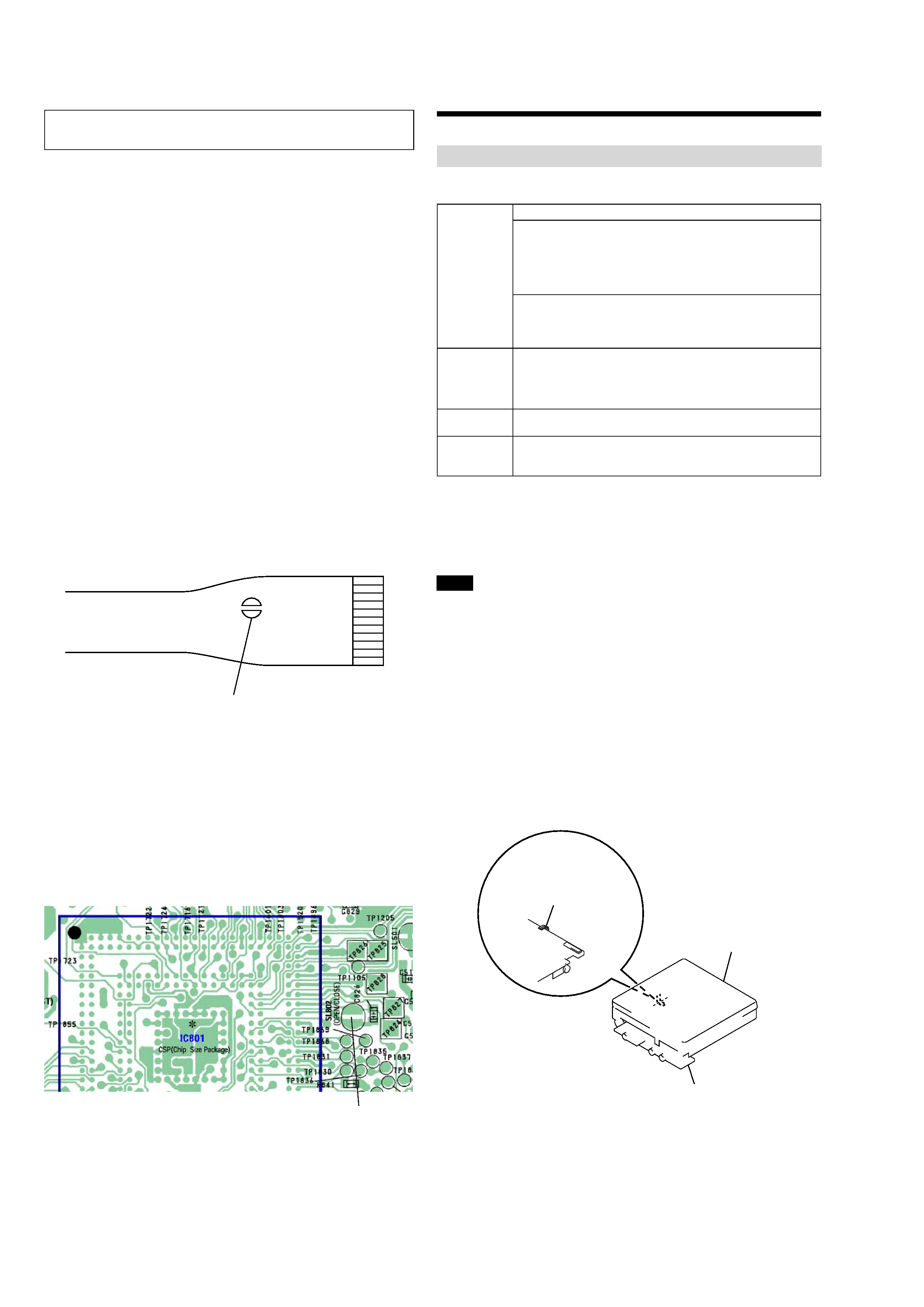
NOTES ON HANDLING THE OPTICAL PICK-UP
BLOCK OR BASE UNIT
The laser diode in the optical pick-up block may suffer electro-
static break-down because of the potential difference generated
by the charged electrostatic load, etc. on clothing and the human
body.
During repair, pay attention to electrostatic break-down and also
use the procedure in the printed matter which is included in the
repair parts.
The flexible board is easily damaged and should be handled with
care.
NOTES ON LASER DIODE EMISSION CHECK
Never look into the laser diode emission from right above when
checking it for adjustment. It is feared that you will lose your sight.
NOTES ON HANDLING THE OPTICAL PICK-UP BLOCK
(LCX-5R)
The laser diode in the optical pick-up block may suffer electro-
static break-down easily. When handling it, perform soldering
bridge to the laser-tap on the flexible board. Also perform mea-
sures against electrostatic break-down sufficiently before the op-
eration. The flexible board is easily damaged and should be handled
with care.
OPTICAL PICK-UP FLEXIBLE BOARD
SECTION 1
SERVICING NOTES
laser-tap
· In performing the repair with the power supplied to the set, re-
moving the MAIN board causes the set to be disabled.
In such a case, make a solder bridge to short SL802 (OPEN/
CLOSE) on the MAIN board in advance.
upper panel assy
MAIN board
FLEXIBLE board
(over write head)
·This set requires the patch data in the nonvolatile memory
(IC852) to be rewritten using the application, when the MAIN
board was replaced. (See page 28)
- MAIN board (Side B) -
SL802
(OPEN/CLOSE)
Handle the FLEXIBLE board (over write head) with care, as it
has been soldered directly to the MAIN board.
In repairing the component side of MAIN board, connect the
FLEXIBLE board (over write head) and the MAIN board with
the lead wires in advance.
Providing the required system environment
The following system environment is required in order to use the SonicStage Ver.2.0/MD
Simple Burner Ver.2.0 software for the MD Walkman.
This software is not supported by the following environments:
OSs other than the indicated above
Personally constructed PCs or operating systems
An environment that is an upgrade of the original manufacturer-installed operating system
Multi-boot environment
Multi-monitor environment
Macintosh
We do not ensure trouble-free operation on all computers that satisfy the system requirements.
The NTFS format of Windows XP/Windows 2000 Professional can be used only with the standard
(factory) settings.
We do not ensure trouble-free operation of the system suspend, sleep, or hibernation function on all
computers.
For Windows 2000 Professional users, install Service Pack 3 or later version before using the
software.
System requirements
Computer
IBM PC/AT or Compatible
· CPU: Pentium II 400 MHz or higher (Pentium III 450 MHz or higher
is recommended.)
· Hard disk drive space: 200 MB or more (1.5 GB or more is
recommended) (The amount space will vary according to Windows
version and the number of music files stored on the hard disk.)
· RAM: 64 MB or more (128 MB or more is recommended)
Others
· CD drive (capable of digital playback by WDM)
· Sound Board
· USB port (supports USB (previously USB 1.1))
Operating
System
Factory installed:
Windows XP Media Center Edition 2004/Windows XP Media Center
Edition/Windows XP Professional/Windows XP Home Edition/
Windows 2000 Professional/Windows Millennium Edition/Windows
98 Second Edition
Display
High Color (16bit) or higher, 800
× 600 dots or better (1024 × 768 dots
or better is recommended)
Others
· Internet access: for Web registration, EMD services and CDDB
· Windows Media Player (version 7.0 or higher) installed for playing
WMA files
Notes
5
MZ-N420D
SECTION 2
GENERAL
This section is extracted from
instruction manual.
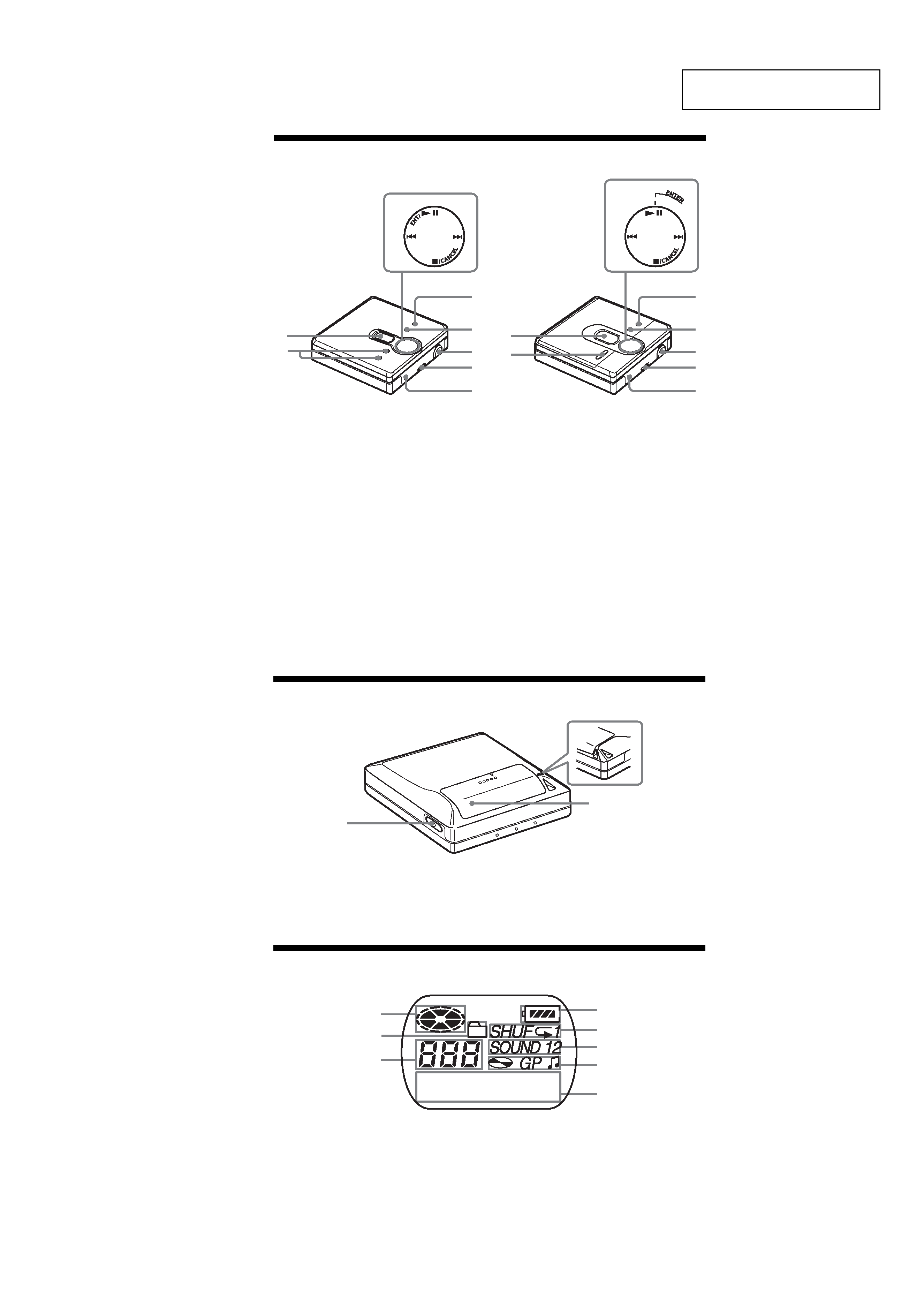
This model comes in two designs with different shapes and names for the buttons.
Front of the player
A Display window
B VOL (VOLUME ) +* and button
* The VOL (VOLUME ) + button has a
tactile dot.
C 4-position control key
ENT/NX (ENTER/NX)
(enter/play/pause)*
. and > (search/AMS)
x/CANCEL (stop/cancel)
* The ENT/NX (ENTER/NX)button
has a tactile dot.
D MENU button
E GROUP button
F USB jack
When connecting to your computer,
connect the dedicated USB cable to
this jack.
G HOLD switch
H i (headphones/earphones) jack
3
3
5
6
7
4
8
1
2
5
6
7
4
8
1
2
On the following pages of this manual, explanations are given
using the illustration in the top-left of this page.
Back of the player
A OPEN button
B Hand strap hole
Use the hole to attach your own strap.
C Battery compartment lid
The display window of the player
A Disc indication
B Group mode indication
Lights up when group mode is on.
C Track number display
D Battery level indication
Shows approximate battery condition.
E Play mode indication
Shows play mode of the MD.
F SOUND indication
G Disc, group, track indication
H Character information display
Displays the track names, elapsed
time, etc.
1
3
2
1
2
3
4
5
6
7
8