1
SERVICE MANUAL
FM/AM PORTABLE MINIDISC RECORDER
Model Name Using Similar Mechanism
MZ-G750/R700
Mechanism Type
MT-MZR700-172
Optical Pick-up Name
LCX-4R
MD recorder
Audio playing system
MiniDisc digital audio system
Laser diode properties
Material: GaAlAs MQW
Wavelength:
= 790 nm
Emission duration: continuous
Laser output: less than 44.6
µW
(This output is the value measured at a
distance of 200 mm from the lens surface
on the optical pick-up block with 7 mm
aperture.)
Recording and playback time
When using MDW-80
Maximum 160 min. in monaural
Maximum 320 min. in stereo
Revolutions
350 rpm to 2,800 rpm (CLV)
Error correction
ACIRC (Advanced Cross Interleave Reed
Solomon Code)
Sampling frequency
44.1 kHz
Sampling rate converter
Input: 32 kHz/44.1 kHz/48 kHz
Coding
ATRAC (Adaptive TRansform Acoustic
Coding)
ATRAC3-LP2
ATRAC3-LP4
SPECIFICATIONS
Modulation system
EFM (Eight to Fourteen Modulation)
Number of channels
2 stereo channels
1 monaural channel
Frequency response
20 to 20,000 Hz ± 3 dB
Wow and Flutter
Below measurable limit
Inputs
Microphone: stereo mini-jack, minimum
input level 0.35 mV
Line in: stereo mini-jack, minimum input
level 49 mV
Optical (Digital) in: optical (digital) mini-
jack
Outputs
i
: stereo mini-jack, maximum output level
5 mW + 5 mW, load impedance 16 ohm
Radio
Frequency range
AM: 531-1,602 kHz
FM: 87.5-108.0 MHz
General
Power requirements
Sony AC Power Adaptor (supplied*)
connected at the DC IN 3 V jack:
230 V AC, 50/60 Hz (AEP, FR, CET
model)
240 V AC, 50 Hz (Australian model)
230-240 V AC, 50 Hz (UK, HK model)
110/220 V AC, 60 Hz (Korean model)
100-240 V AC, 50/60 Hz (E, JE model)
Nickel cadmium rechargeable battery
NC-WMAA (supplied)
LR6 (size AA) alkaline battery (not
supplied)
*) Except for Korean model
·Abbreviation
FR
: French model
CET : East European & CIS model
JE
: Tourist model
HK
: Hong Kong model
Continued on next page
US and foreign patents licensed
from Dolby Laboratories.
Ver 1.0 2001. 01
Ver 1.0 2002. 04
Sony Corporation
Personal Audio Company
Published by Sony Engineering Corporation
9-873-965-01
2002D0400-1
© 2002. 04
AEP Model
UK Model
E Model
Australian Model
Tourist Model
MZ-G755
The CE mark is valid
only for products
marketed in the
European Union.
2
Flexible Circuit Board Repairing
· Keep the temperature of the soldering iron around 270°C
during repairing.
· Do not touch the soldering iron on the same conductor of the
circuit board (within 3 times).
· Be careful not to apply force on the conductor when soldering
or unsoldering.
Notes on chip component replacement
· Never reuse a disconnected chip component.
· Notice that the minus side of a tantalum capacitor may be
damaged by heat.
CAUTION
Use of controls or adjustments or performance of procedures
other than those specified herein may result in hazardous
radiation exposure.
Battery operation time
Battery life
When recording1) 2)
(Unit: approx.hours) (JEITA3))
Batteries
Stereo
LP2
LP4
NC-WMAA Nickel Cadmium
4
6
7.5
rechargeable battery4)
LR6 (SG) Sony alkaline dry
96)
136)
166)
battery5)
When playing1)
(Unit: approx.hours) (JEITA3))
Batteries
Stereo
LP2
LP4
NC-WMAA Nickel Cadmium
11.5
14
16
rechargeable battery4)
LR6 (SG) Sony alkaline dry
36
42
48
battery5)
When using the radio1)
(JEITA3))
Batteries
Approx. hours
NC-WMAA Nickel Cadmium rechargeable
9.5
battery4)
LR6 (SG) Sony alkaline dry battery5)
28.5
1)
The battery life may be shorter due to operating conditions, the
temperature of the location, and varieties of batteries.
2)
When you record, use a fully charged rechargeable battery.
3)
Measured value by the standard of JEITA (Japan Electronics and
Information Technology Industries Association).
4)
When using a 100% fully charged rechargeable battery.
5)
When using a Sony LR6 (SG) "STAMINA" alkaline dry battery
(produced in Japan).
6)
Recording time may differ according to the alkaline batteries.
Dimensions
Approx. 81
× 28.1 × 74.4 mm (w/h/d)
without projections.
Mass
Approx. 118 g the recorder only
Supplied accessories
NC-WMAA nickel cadmium rechargeable battery (1)
AC power adaptor (Except for Korean model) (1)
AC plug adaptor (Tourist model only) (1)
Headphones/earphones with a remote control (1)
Optical cable (1)
Rechargeable battery carrying case (1)
Carrying pouch/carrying case with a belt clip (1)
Design and specifications are subject to change
without notice.
SAFETY-RELATED COMPONENT WARNING!!
COMPONENTS IDENTIFIED BY MARK 0 OR DOTTED LINE
WITH MARK 0 ON THE SCHEMATIC DIAGRAMS AND IN
THE PARTS LIST ARE CRITICAL TO SAFE OPERATION.
REPLACE THESE COMPONENTS WITH SONY PARTS WHOSE
PART NUMBERS APPEAR AS SHOWN IN THIS MANUAL
OR IN SUPPLEMENTS PUBLISHED BY SONY.
ATTENTION AU COMPOSANT AYANT RAPPORT
À LA SÉCURITÉ!!
LES COMPOSANTS IDENTIFIÉS PAR UNE MARQUE 0 SUR
LES DIAGRAMMES SCHÉMATIQUES ET LA LISTE DES
PIÈCES SONT CRITIQUES POUR LA SÉCURITÉ DE
FONCTIONNEMENT. NE REMPLACER CES COMPOSANTS
QUE PAR DES PIÈCES SONY DONT LES NUMÉROS SONT
DONNÉS DANS CE MANUEL OU DANS LES SUPPLÉMENTS
PUBLIÉS PAR SONY.
MZ-G755

3
1. SERVICING NOTE ......................................................... 4
2. GENERAL
Looking at the controls ....................................................... 5
3. DISASSEMBLY
3-1. Bottom Panel Assy .............................................................. 6
3-2. Upper Panel Assy ................................................................ 7
3-3. LCD Module ....................................................................... 7
3-4. Main Board ......................................................................... 8
3-5. MD Mechanism Deck ......................................................... 8
3-6. OP Service Assy .................................................................. 9
3-7. Holder Assy ......................................................................... 9
3-8. Motor Flexible Board ........................................................ 10
3-9. DC Motor (M602) ............................................................. 10
3-10. DC Motor (M601), DC Motor (M603) ............................. 11
4. TEST MODE
4-1. Outline ............................................................................... 12
4-2. Setting Method of Test Mode ............................................ 12
4-3. Operation in Setting the Test Mode ................................... 12
4-4. Releasing the Test Mode ................................................... 12
4-5. Configuration of Test Mode .............................................. 13
4-6. Manual Mode .................................................................... 13
4-7. Overall Adjustment Mode ................................................. 14
4-8. Self-diagnosis Result Display Mode ................................. 14
4-9. Result the Error Display Code .......................................... 15
4-10. Sound Skip Check Result Display Mode .......................... 16
4-11. Key Check Mode ............................................................... 16
TABLE OF CONTENTS
5. ELECTRICAL ADJUSTMENTS
5-1. Outline ............................................................................... 18
5-2. Precautions for Adjustment ............................................... 18
5-3. Adjustment Sequence ........................................................ 18
5-4. NV Reset ........................................................................... 18
5-5. Power Supply Manual Adjustment .................................... 19
5-6. Temperature Correction ..................................................... 20
5-7. Laser Power Check ........................................................... 20
5-8. Overall Adjustment Mode ................................................. 21
6. DIAGRAMS
6-1. IC Pin Descriptions .......................................................... 24
6-2. Block Diagram Servo Section ..................................... 31
6-3. Block Diagram Audio Section .................................... 32
6-4. Block Diagram System Control/Power Section .......... 33
6-5. Printed Wiring Board Main Section ............................ 34
6-6. Schematic Diagram Main Section (1/3) ...................... 37
6-7. Schematic Diagram Main Section (2/3) ...................... 38
6-8. Schematic Diagram Main Section (3/3) ...................... 39
6-9. IC Block Diagrams ............................................................ 40
7. EXPLODED VIEWS
7-1. Panel Section ..................................................................... 43
7-2. Chassis Section ................................................................. 44
7-3. MD Mechanism Deck Section .......................................... 45
8. ELECTRICAL PARTS LIST ...................................... 46
MZ-G755
4
MZ-G755
SECTION 1
SERVICING NOTE
NOTES ON HANDLING THE OPTICAL PICK-UP
BLOCK OR BASE UNIT
The laser diode in the optical pick-up block may suffer electro-
static break-down because of the potential difference generated
by the charged electrostatic load, etc. on clothing and the human
body.
During repair, pay attention to electrostatic break-down and also
use the procedure in the printed matter which is included in the
repair parts.
The flexible board is easily damaged and should be handled with
care.
NOTES ON LASER DIODE EMISSION CHECK
Never look into the laser diode emission from right above when
checking it for adjustment. It is feared that you will lose your sight.
NOTES ON HANDLING THE OPTICAL PICK-UP BLOCK
(LCX-4R)
The laser diode in the optical pick-up block may suffer electro-
static break-down easily. When handling it, perform soldering
bridge to the laser-tap on the flexible board. Also perform mea-
sures against electrostatic break-down sufficiently before the op-
eration. The flexible board is easily damaged and should be handled
with care.
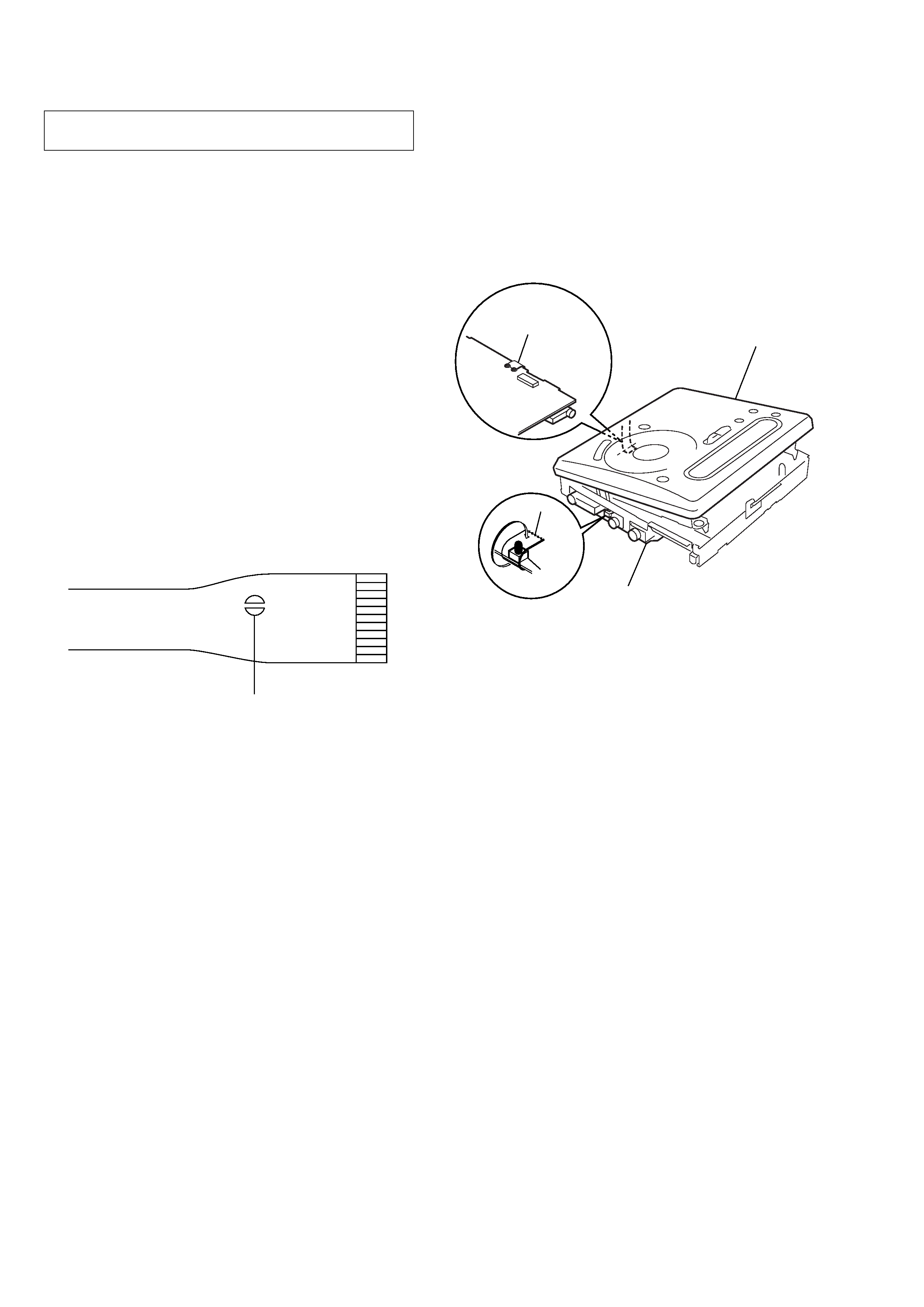
OPTICAL PICK-UP FLEXIBLE BOARD
· In performing the repair with the power supplied to the set,
removing the MAIN board causes the set to be disabled.
In such a case, fix a convex part of the open/close detect switch
(S806 on MAIN board) with a tape in advance.
Handle the FLEXIBLE board (over write head) with care, as it
has been soldered directly to the MAIN board.
In repairing the component side of MAIN board, connect the
FLEXIBLE board (over write head) and the MAIN board with
the lead wires in advance. (See page 8)
· Replacement of CDX2674-204GA (IC801) used in this set
requires a special tool.
· On the set having the microcomputer version 1.000, some
adjusted values were set in the manual mode at the shipment,
but these data will be cleared when the NV is reset. Therefore,
on the set having the microcomputer version 1.000, change the
adjusted values following the Change of Adjusted Values
immediately after the NV was reset. (See page 18)
· If the nonvolatile memory was replaced on the set, the modified
program data must be written to the nonvolatile memory. In such
a case, write the modified data that meets the microcomputer
version following the patch data rewriting procedure at the
replacement of nonvolatile memory. (See page 23)
laser-tap
S806
MAIN board
FLEXIBLE board
(Over write head)
Tape
upper panel assy
5
MZ-G755
SECTION 2
GENERAL
This section is extracted from
instruction manual.
6
See pages in ( ) for more details.
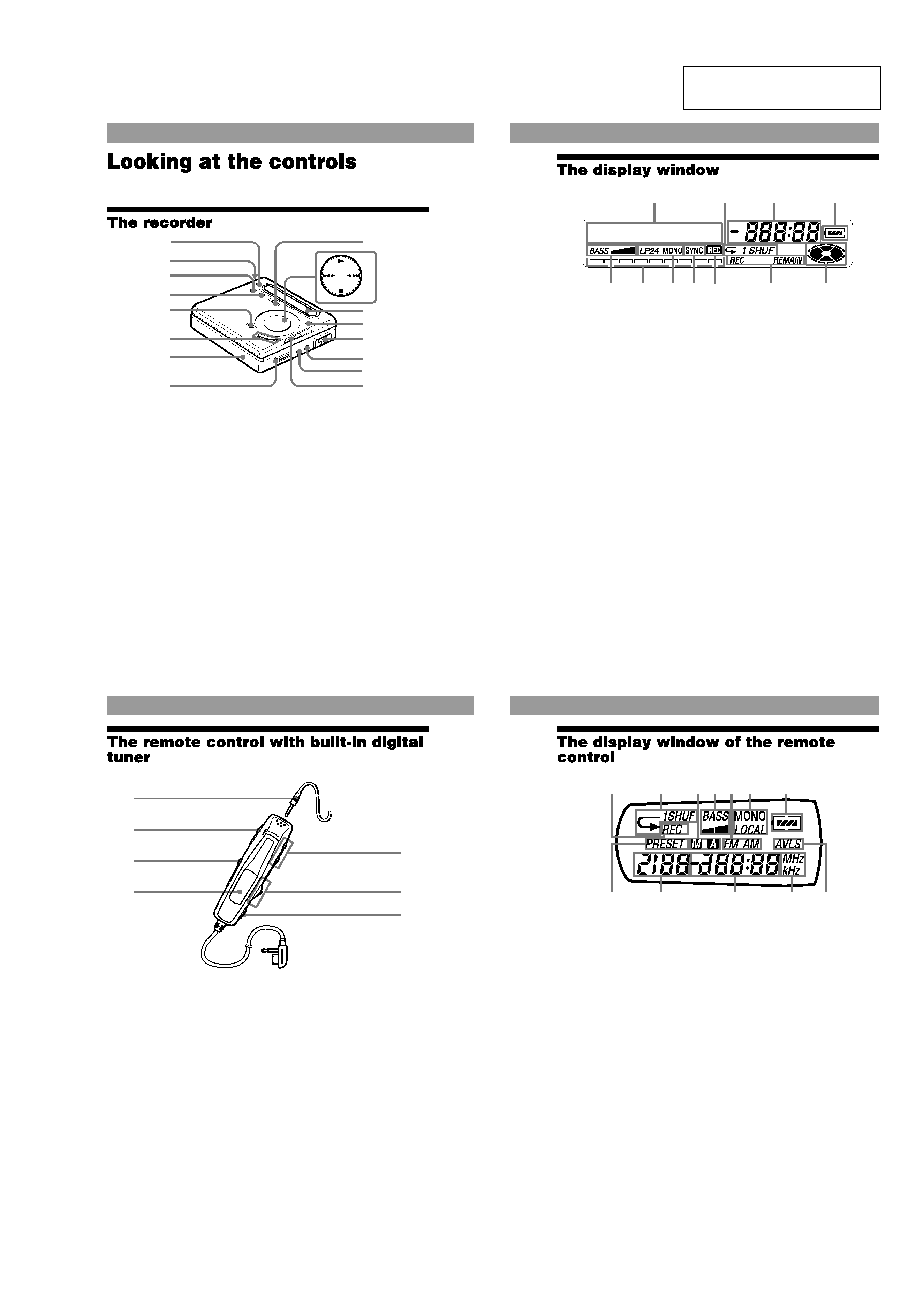
A REC MODE button (25)
B OPEN button (11)
C T MARK button (51)
D END SEARCH button
(14)(55)
E X (pause) button
(15)(18)(32)(55)
F VOL +/ button (17)(55)
The VOL + button has a
tactile dot.
G DC IN 3V jack (10)(13)
H i (headphones/earphones)
jack (11)(42)
I REC (record) switch
(14)(24)
J <SELECT, button
(27)(36)(49)
N (play) button (14)(17)
The N button has a tactile
dot.
./> (search/AMS)
button (15)(18)(52)(55)
CHARGE/x (stop) button
(10)(14)(17)(26)(49)
K Display window (27)(36)
L MENU/ENTER button
(26)(36)(48)
M Battery compartment (10)
N LINE IN (OPTICAL) jack
(13)(24)
O MIC (PLUG IN POWER)
jack (29)
There is a tactile dot beside
the MIC (PLUG IN POWER)
jack.
P HOLD switch (11)(41)
SELECT
CHARGE
A
B
C
E
G
F
H
J
K
L
M
O
P
N
I
D
7
A Character information
display (34)(39)
Displays the disc and track
names, error messages, track
numbers, etc.
B Play mode indication (36)
Shows the play mode of the
MD.
C Time display
D Battery indication (58)
Shows approximate battery
condition.
E Mega bass indication (38).
F Level meter (33)
Shows the volume of the
MD being played or
recorded.
G Recording mode (LP2/LP4/
MONO) indication (25)
H SYNC (synchro-recording)
indication
I REC indication (14)
Lights up while recording.
When flashing, the recorder
is in record standby mode.
J REC REMAIN/REMAIN
(remaining time/tracks)
indication (34)(39)
Lights up along with the
remaining time of the track,
the remaining time of the
MD, or the remaining
number of tracks.
K Disc indication
Shows that the disc is
rotating for recording,
playing or editing an MD.
I
E
F
G H
K
J
AB
D
C
8
A Headphones/earphones
Can be replaced with
optional headphones/
earphones.
B HOLD switch (11)(41)
Slide to lock the controls of
the remote control.
C RADIO ON/BAND button
(20)(44)
FM MODE button (21)
D Display window (44)
E VOL +/ buttons (17)(20)
F Jog lever
X (pause)/MODE (18)(44)
>N (AMS/search,
play)/F+ button (17)(20)(45)
. (AMS/search)/F
button(18)(20)(45)
G x (stop)/RADIO OFF
button (17)(21)(47)
B
A
C
D
E
F
G
9
A REC indication (14)
Lights up while recording.
When flashing, the recorder
is in record standby mode.
B Play mode indication (36)
Shows the play mode of the
MD.
C Manual/Auto indication
D Mega Bass indication (38)
E FM/AM indication (44)
F MONO (monaural)/LOCAL
indication
G Battery indication
H PRESET indication (44)
Lights up while preset radio
station is turned on.
I Number display
Displays the preset numbers,
track numbers, etc.
J Time/Frequency display
K MHz/kHz indication (44)
MHz lights up when FM
station is turned on and kHz
lights up when AM station is
turned on.
L AVLS indication (40)
A
HI
J
K
L
BC D E F
G