MICROFILM
SERVICE MANUAL
PORTABLE MINIDISC PLAYER
E Model
Tourist Model
Model Name Using Similar Mechanism
MZ-E55
Mechanism Type
MT-MZE55-150
Optical Pick-Up Name
ODX-1B
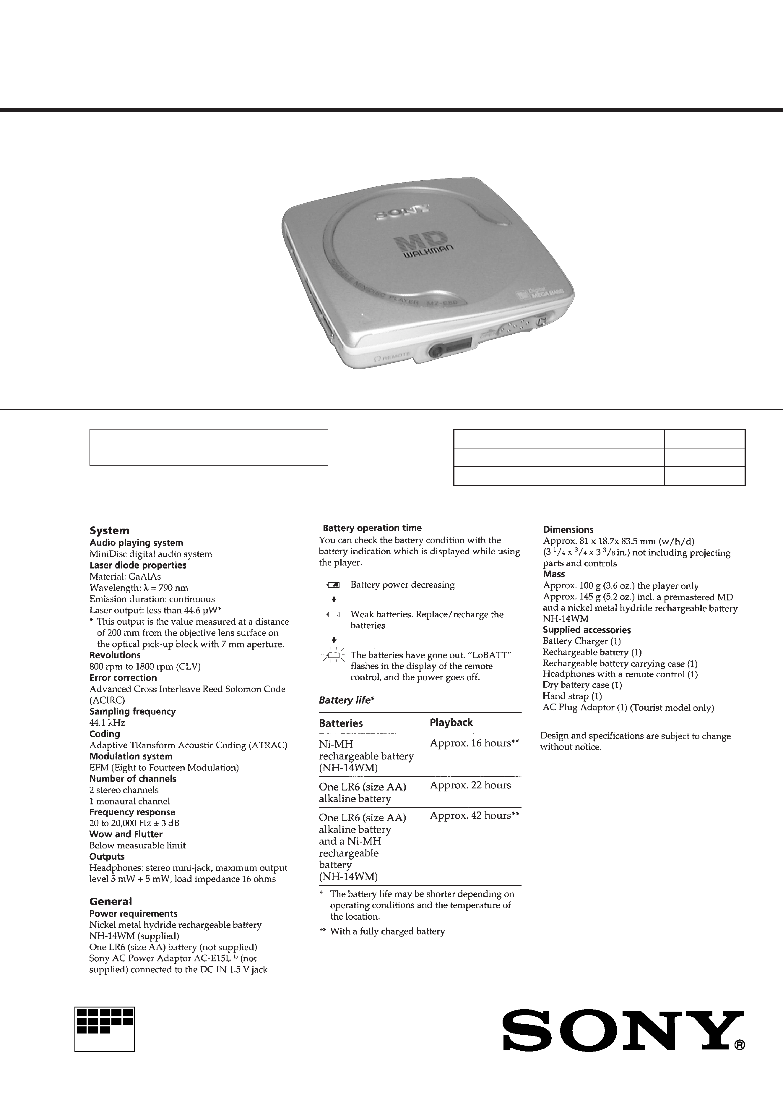
SPECIFICATIONS
MZ-E80
US and foreign patents licensed from Dolby
Laboratories Licensing Corporation.
Photo: Silver
Ver 1.0 1999. 07
2
TABLE OF CONTENTS
1.
SERVICING NOTES ............................................... 2
2.
GENERAL ................................................................... 3
3.
DISASSEMBLY ......................................................... 4
4.
TEST MODE .............................................................. 6
5.
ELECTRICAL ADJUSTMENTS ......................... 10
6.
DIAGRAMS
6-1. Block Diagram ................................................................ 11
6-2. Printed Wiring Boards .................................................... 16
6-3. Schematic Diagram ......................................................... 19
6-4. IC Pin Function Description ........................................... 28
7.
EXPLODED VIEWS ................................................ 35
8.
ELECTRICAL PARTS LIST ............................... 37
Flexible Circuit Board Repairing
· Keep the temperature of the soldering iron around 270 °C dur-
ing repairing.
· Do not touch the soldering iron on the same conductor of the
circuit board (within 3 times).
· Be careful not to apply force on the conductor when soldering
or unsoldering.
Notes on chip component replacement
· Never reuse a disconnected chip component.
· Notice that the minus side of a tantalum capacitor may be dam-
aged by heat.
SAFETY-RELATED COMPONENT WARNING!!
COMPONENTS IDENTIFIED BY MARK
! OR DOTTED
LINE WITH MARK
! ON THE SCHEMATIC DIAGRAMS
AND IN THE PARTS LIST ARE CRITICAL TO SAFE
OPERATION. REPLACE THESE COMPONENTS WITH
SONY PARTS WHOSE PART NUMBERS APPEAR AS
SHOWN IN THIS MANUAL OR IN SUPPLEMENTS PUB-
LISHED BY SONY.
CAUTION
Use of controls or adjustments or performance of procedures
other than those specified herein may result in hazardous ra-
diation exposure.
SECTION 1
SERVICING NOTES
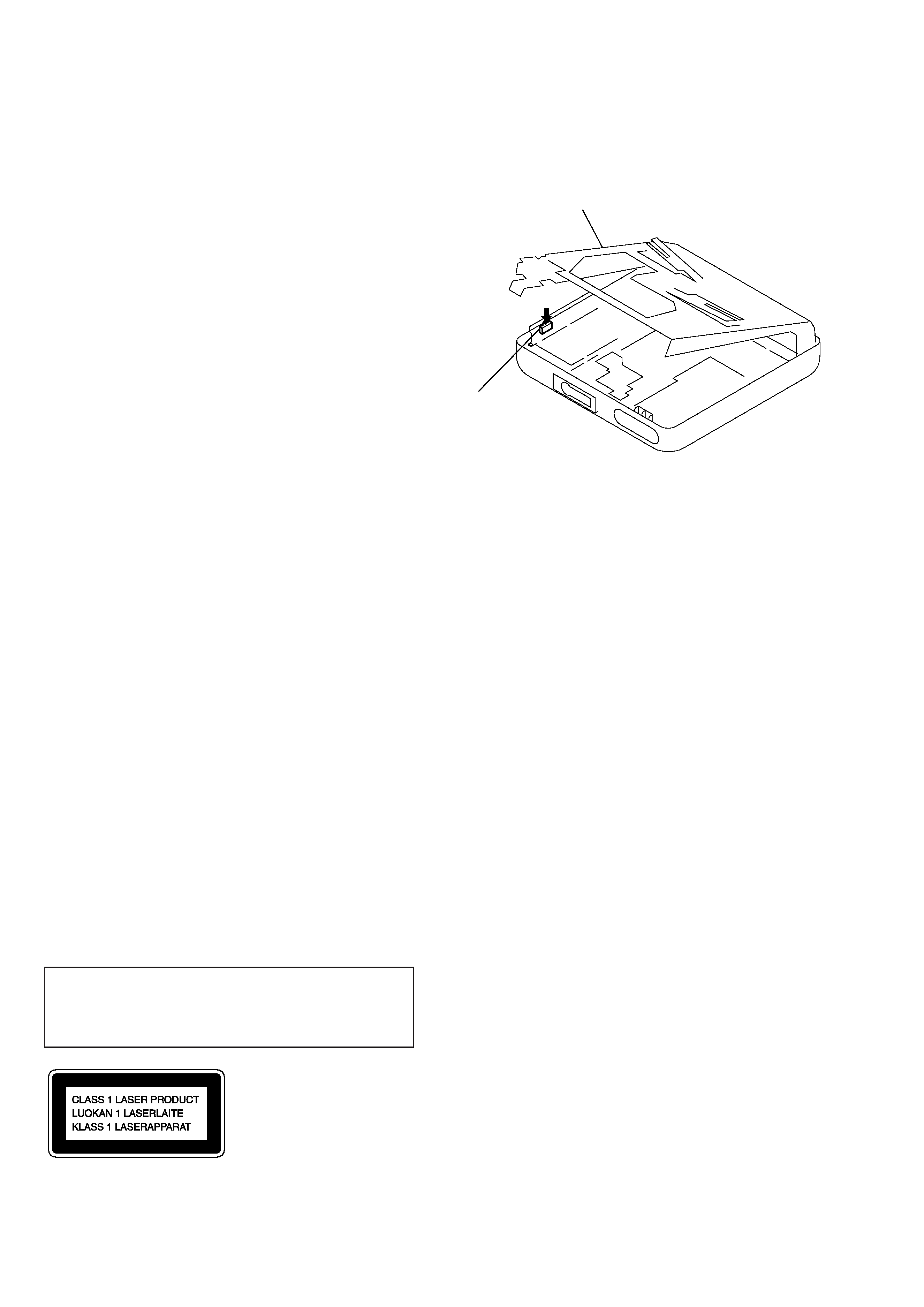
This MiniDisc player is classified as a CLASS 1
LASER product.
The CLASS 1 LASER PRODUCT label is located
on the bottom exterior.
· Removing the mechanism deck causes this set to be disabled
during a repair with the power supplied to the set. Therefore,
lock convex portion of open/close detect switch (S801) during
a repair.
· Replacement of CXD2663GA (IC601) used in this set requires
a special tool. Therefore, it cannot be replaced.
Mechanism deck section
Open/close detect
switch (S801)
3
SECTION 2
GENERAL
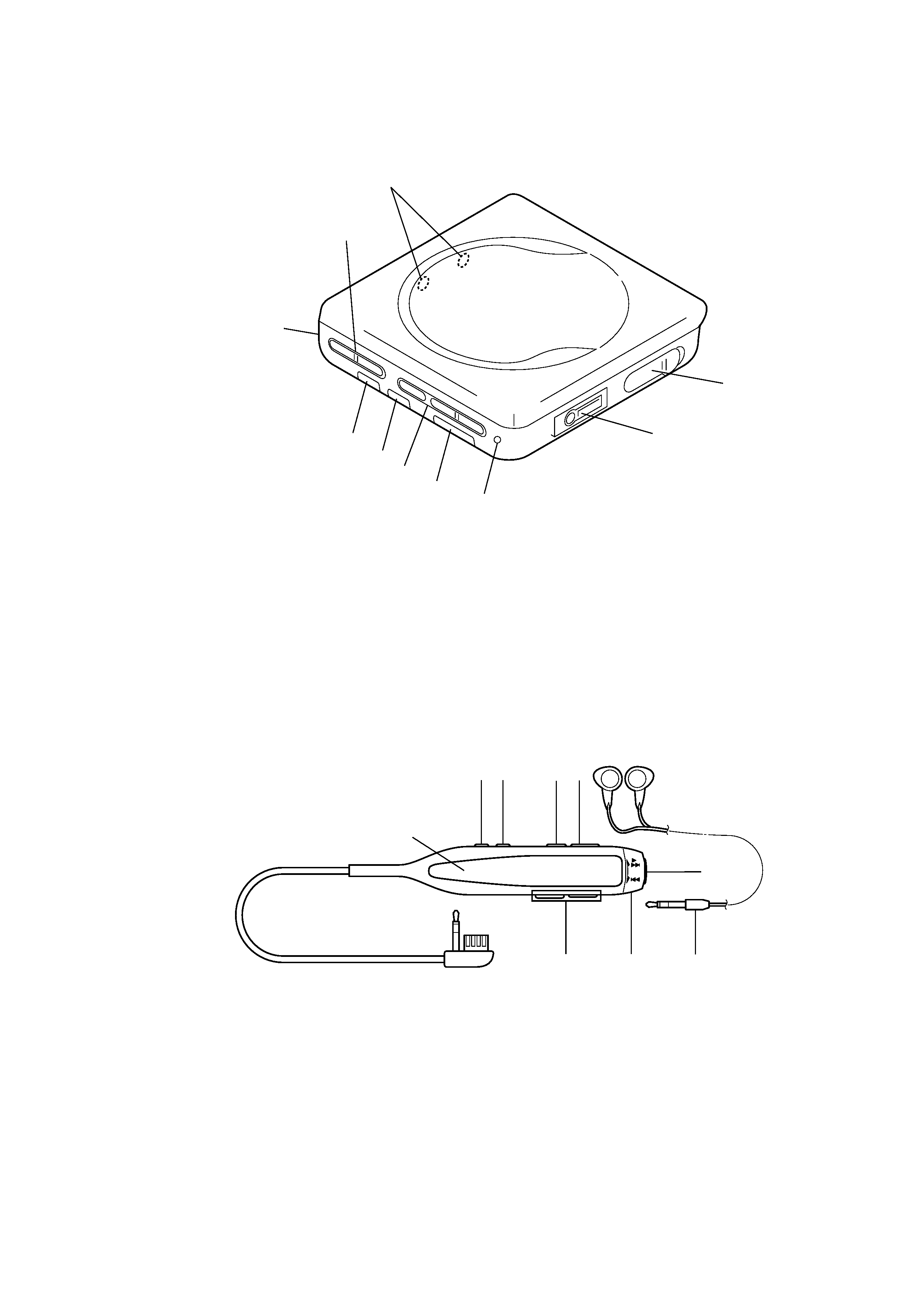
1 OPERATE indicator
2 HOLD switch
3 DIGITAL MEGABASS switch
4 AVLS switch
5 Battery cover
6 VOLUME +/ buttons
7 MD operate buttons
+/" ( FF · PLAY )
= (REW )
p (STOP)
8 External battery terminal (+/)
9 OPEN switch
!º
2 REMOTE jack
1 Headphone
2 MD operate switch
"/+ (PLAY · FF)
= (REW)
3 VOL +/ buttons
4 Display window
5 DISPLAY button
6 PLAYMODE button
7 P (PAUSE) button
8 HOLD c switch
9 p (STOP) button
8
7
6
5
4
3
2
1
0
9
8
7
6
5
4
3
21
9
· LOCATION OF CONTROLS
Main Unit
Remote commander with headphone
4
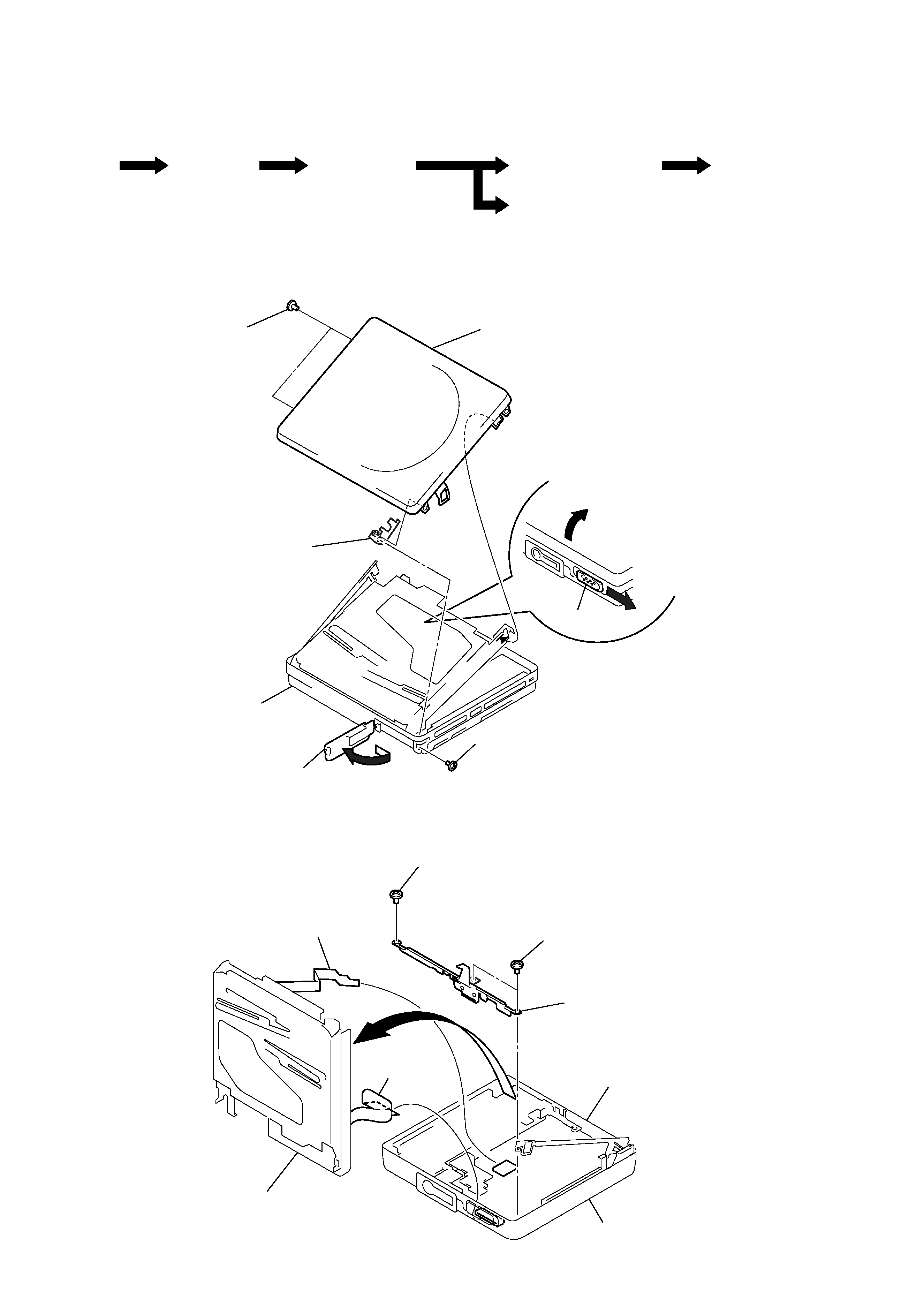
UPPER LID ASSY
MECHANISM DECK SECTION (MT-MZE55-150)
Note: Follow the disassembly procedure in the numerical order given.
SECTION 3
DISASSEMBLY
Set
Upper lid assy
Mechanism deck
section
(MT-MZE55-150)
SW board
Main Board, Audio board
Optical pick-up section
· This set can be disassembled in the order shown below.
5 two screws
(M1.4
× 1.6)
6 fulcrum plate (L)
assy
main section
7 upper lid assy
1 knob (open)
2
4 screw (M1.4
× 1.3)
3 lid
(battery case)
1 screw
(B1.4
× 3)
1 two screws
(B1.4
× 2.3)
2 Open slider assy
main board
main section
5 mechanism deck section
4 flexible board
(CN501)
3 flexible board
(CN551)
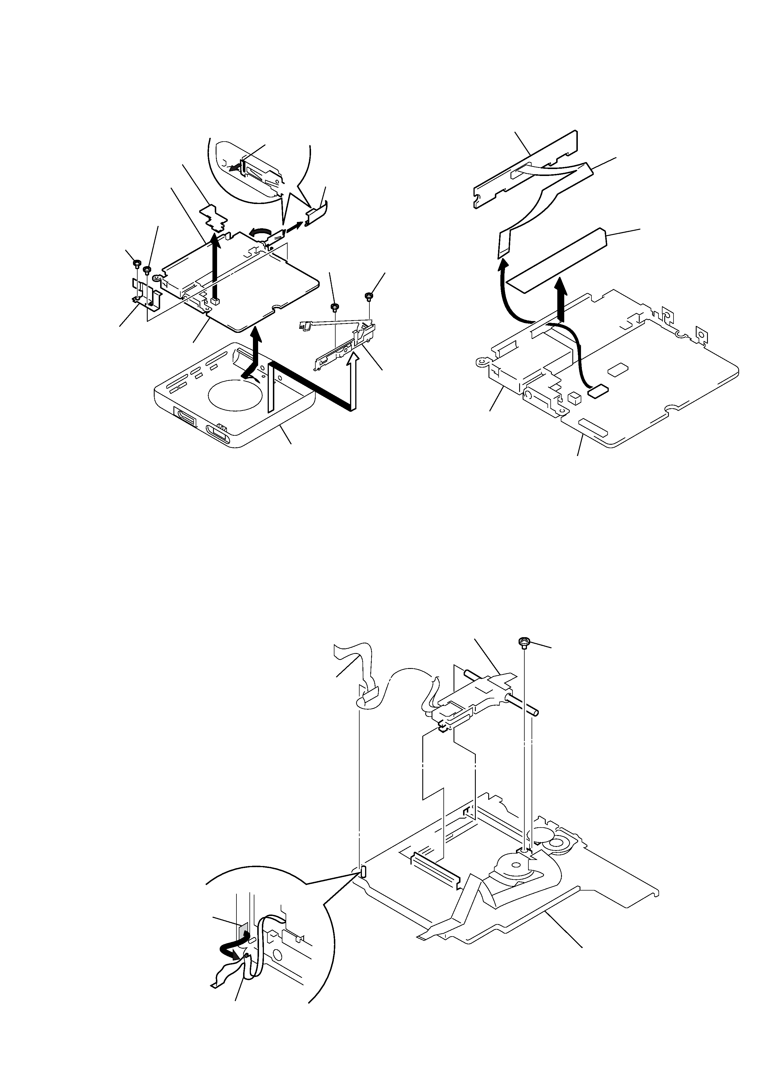
5
MAIN BOARD, AUDIO BOARD
OPTICAL PICK-UP SECTION
8 main board
5 bracket
4 screw
(B1.4
× 2.5)
4 screw
(B1.4
× 2.3)
9 audio board
*1
1 claw
2 lid (battery case)
3
battery case
6 screw
(1.4
× 3)
7 fulcrum plate
(R) assy
bottom panel assy
6 screw
(1.4
× 2)
3 SW board
2 flexible board
1 caution label
*2
battery case
main board
*1 Note: In removing the Audio board, raise the
connector section uprightly.
*2 Note: If the SW board or flexible board is removed,
the caution label (4-213-092-01) on the flex-
ible board will be defaced or deformed, and
replace it with a new label.
2 flexible board
4 optical pick-up
section
3 screw
(M1.4
× 2.5)
chassis assy
1 flexible board
adhesive sheet
SW BOARD