MZ-E500
AEP Model
UK Model
Australian Model
E Model
SERVICE MANUAL
PORTABLE MINIDISC PLAYER
SPECIFICATIONS
Model Name Using Similar Mechanism
NEW
MD Mechanism Type
MT-MZE500-174
Optical Pick-up Mechanism Type
LCX-4E
US and foreign patents licensed from Dolby
Laboratories Licensing Corporation
Audio playing system
MiniDisc digital audio system
Laser diode properties
Material: GaAlAs
Wavelength:
= 790 nm
Emission duration: continuous
Laser output: less than 44.6
µW*
* This output is the value measured at a distance of 200 mm from the
objective lens surface on the optical pick-up block with 7 mm aperture.
Revolutions
Approx. 300 rpm to 2,700 rpm
Error correction
ACIRC (Advanced Cross Interleave Reed Solomon Code)
Sampling frequency
44.1 kHz
Coding
ATRAC (Adaptive Transform Acoustic Coding)
ATRAC3: LP2
ATRAC3: LP4
Modulation system
EFM (Eight to Fourteen Modulation)
Number of channels
2 stereo channels
1 monaural channel
Frequency response
20 to 20,000 Hz
± 3 dB
Wow and Flutter
Below measurable limits
Outputs
Headphones/earphones: stereo mini-jack, maximum output level 5 mW +
5 mW, load impedance 16 ohms
Power requirements
Nickel Cadmium rechargeable battery
One NC-6WM (supplied): 1.2V, 600 mAh
One LR6 (size AA) battery (not supplied)
External power jack: Power rating 1.5V DC
Battery operation time
Dimensions
Approx. 74.5
× 17.7 × 80.5 mm (w/h/d) (3 × 23/
32 × 3
1/
4 in.)
(not including projecting parts and controls)
Mass
Approx. 76g (2.7 oz) (the player only)
Supplied accessories
Headphones/earphones with a remote control (1)
Battery charger (1)
Rechargeable battery (1)
Rechargeable battery carrying case (1)
Dry battery case (1)
Carrying pouch (1) (except for the U.S.A model)
AC plug adaptor (1) (world model only)
Design and specifications are subject to change without notice.
Battery life
(EIAJ1))
Batteries
Ni-Cd rechargeable
battery NC-6WM2)
LR6 (SG) Sony
Alkaline dry battery3)
LR6 (SG)3) and
NC-6WM2)
(Unit: Approx. hours)
1)
Measured in accordance with the EIAJ (Electronic Industries
Association of Japan) standard (using a Sony MDW-series Mini-disc).
2)
With a fully charged battery
3)
When using a Sony LR6 (SG) "STAMINA" alkaline dry battery
(produced in Japan).
Note
The battery life may be shorter depending on operating conditions, the
surrounding temperature, and the battery type.
Stereo (normal)
LP2 Stereo
LP4 Stereo
14
16
18
42
49
58
59
65
75
Ver 1.0 2000. 12

-- 2 --
1. SERVICING NOTE ···················································· 3
2. GENERAL ·································································· 4
3. DISASSEMBLY
3-1. "Panel Block Assy, Upper",
"Holder Assy" ································································· 5
3-2. Mechanism Deck ···························································· 5
3-3. Bracket Assy ··································································· 6
3-4. Main Board ····································································· 6
3-5. Optical Pick-up Block ···················································· 7
4. TEST MODE ······························································ 8
5. ELECTRICAL ADJUSTMENTS ··························· 12
6. DIAGRAMS
6-1. Block Diagram ······························································ 17
6-2. Printed Wiring Boards Main Section (1/2) ············· 19
6-3. Printed Wiring Boards Main Section (2/2) ············· 21
6-4. Schematic Diagram Main Section (1/3) ·················· 23
6-5. Schematic Diagram Main Section (2/3) ·················· 25
6-6. Schematic Diagram Main Section (3/3) ·················· 27
6-7. IC Block Diagrams ······················································· 29
6-8. IC Pin Function Description ········································· 31
7. EXPLODED VIEWS
7-1. Main Section ································································· 37
7-2. Mechanism Deck Section (MT-MZE500-174) ············· 38
8. ELECTRICAL PARTS LIST ·································· 39
SAFETY-RELATED COMPONENT WARNING!!
COMPONENTS IDENTIFIED BY MARK
! OR DOTTED LINEWITH
MARK
!ON THE SCHEMATIC DIAGRAMS AND IN THE PARTS
LIST ARE CRITICAL TO SAFE OPERATION.
REPLACE THESE COMPONENTS WITH SONY PARTS WHOSE
PART NUMBERS APPEAR AS SHOWN IN THIS MANUAL OR IN
SUPPLEMENTS PUBLISHED BY SONY.
Flexible Circuit Board Repairing
· Keep the temperature of the soldering iron around 270°C during
repairing.
· Do not touch the soldering iron on the same conductor of the
circuit board (within 3 times).
· Be careful not to apply force on the conductor when soldering or
unsoldering.
Notes on chip component replacement
· Never reuse a disconnected chip component.
· Notice that the minus side of a tantalum capacitor may be dam-
aged by heat.
TABLE OF CONTENTS
CAUTION
Use of controls or adjustments or performance of
procedures other than those specified herein may result in
hazardous radiation exposure.
-- 3 --
* Replacement of CXD2671-203GA (IC601) used in this set
requires a special tool.
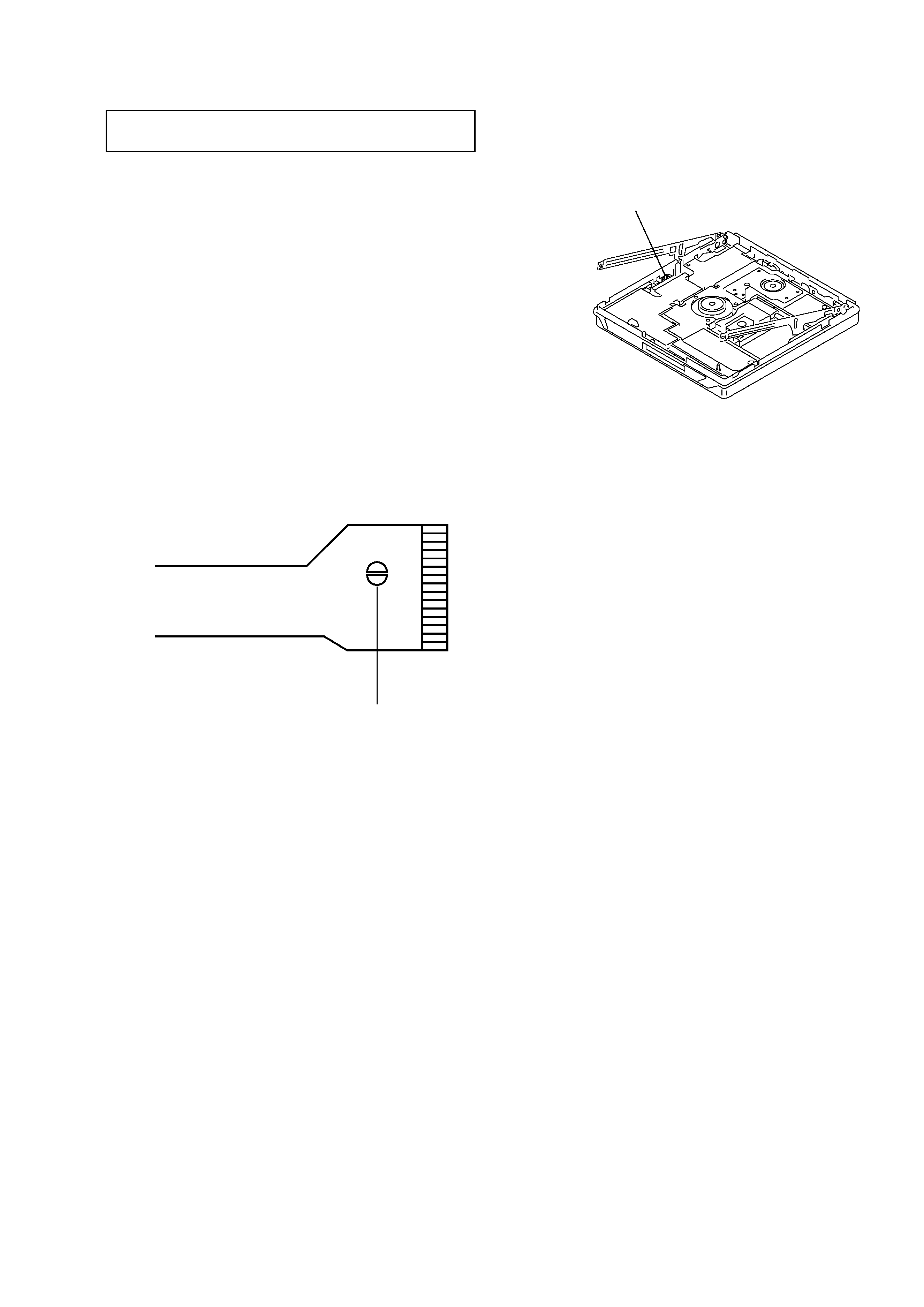
When repairing this device with the power on, if you remove the
main board, this device stops working.
In this case, you work without the device stopping by fastening the
hook of the Open/Close detection switch (S809).
SECTION 1
SERVICING NOTES
NOTES ON HANDLING THE OPTICAL PICK-UP
BLOCK OR BASE UNIT
The laser diode in the optical pick-up block may suffer electrostatic
break-down because of the potential difference generated by the
charged electrostatic load, etc. on clothing and the human body.
During repair, pay attention to electrostatic break-down and also
use the procedure in the printed matter which is included in the
repair parts.
The flexible board is easily damaged and should be handled with
care.
NOTES ON LASER DIODE EMISSION CHECK
Never look into the laser diode emission from right above when
checking it for adjustment. It is feared that you will lose your sight.
NOTES ON HANDLING THE OPTICAL PICK-UP BLOCK
(LCX-4E)
The laser diode in the optical pick-up block may suffer electrostatic
break-down easily. When handling it, perform soldering bridge to
the laser-tap on the flexible board. Also perform measures against
electrostatic break-down sufficiently before the operation. The
flexible board is easily damaged and should be handled with care.
OPTICAL PICK-UP FLEXIBLE BOARD
laser-tap
Open/Colse detection switch (S809)
-- 4 --
SECTION 2
GENERAL
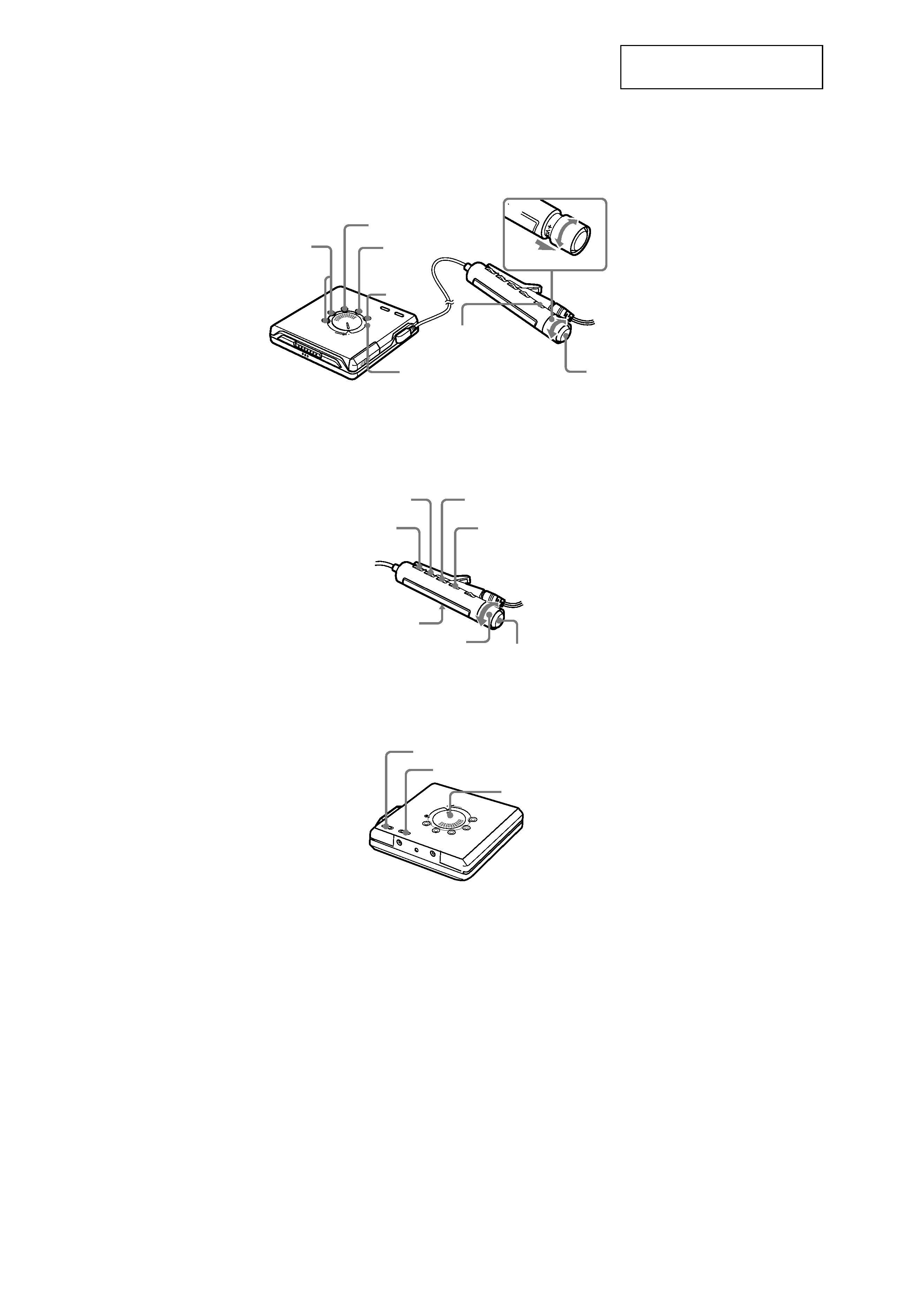
LOCATION AND FUNCTION OF CONTROLS
This section is extracted from
instruction manual.
.
x
VOL +/
x
X
1N >
.
N >
VOL+
VOL
2
./N >
VOL +/
HOLD
DISPLAY
SOUND
PLAYMODE
RPT/ENT
x
HOLD
AVLS
PLAY MODE
OPERATE lamp
Indicador OPERATE
-- 5 --
r
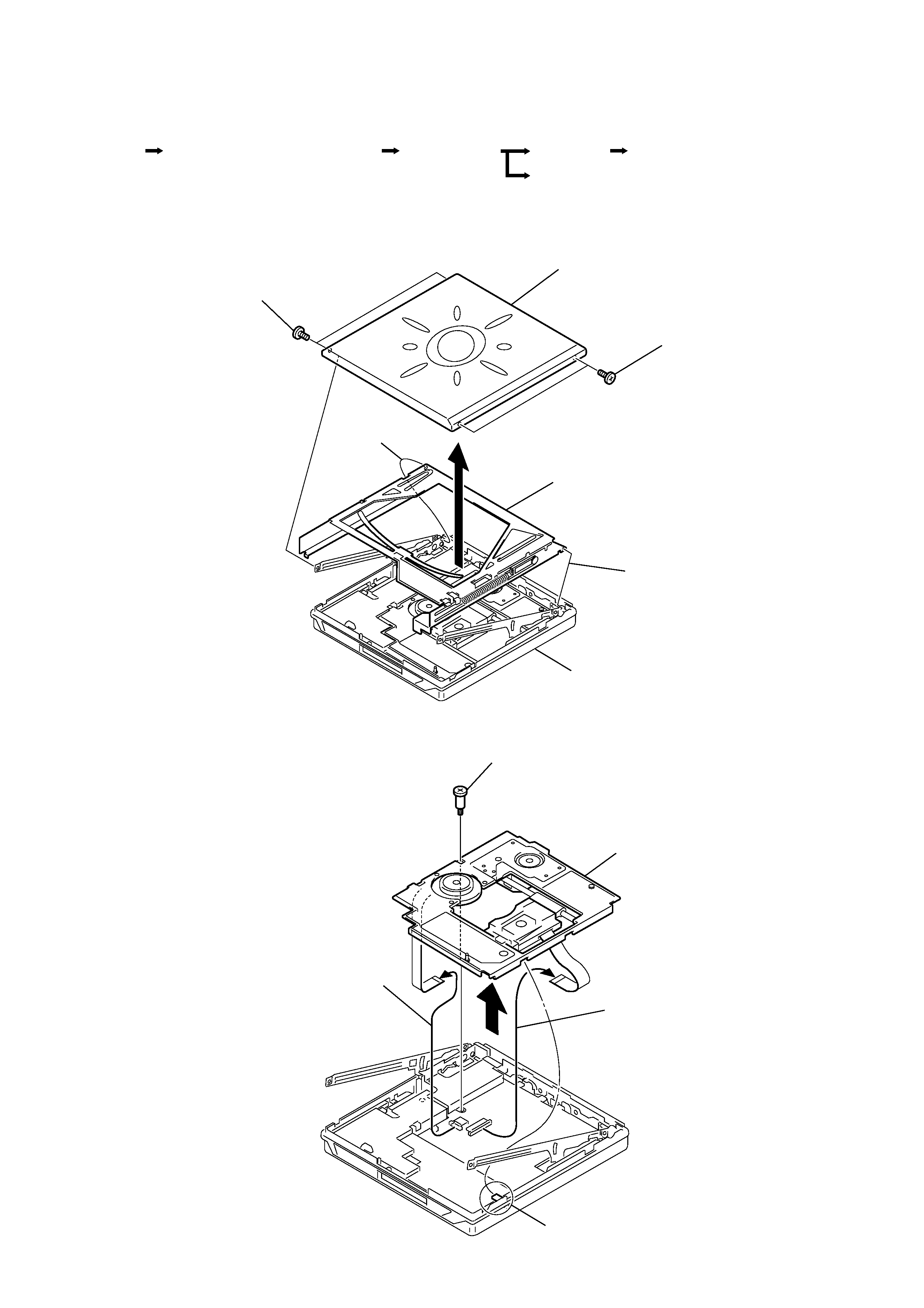
Disassemble the unit in the order as shown below.
Note : Follow the disassembly procedure in the numerical order given.
3-1. "PANEL BLOCK ASSY, UPPER","HOLDER ASSY"
3-2. MECHANISM DECK
SECTION 3
DISASSEMBLY
Optical pick-up block
Mechanism deck
"Panel block assy,upper","Holder assy"
Set
Bracket assy
Main board
Panel block assy, upper
1
Screws (MI 1.4
× 2.5)
3
Move it away
from projection
Case (rear)
Holder assy
2
1
Screws (MI 1.4
× 1.6)
3
Move it away
from projection
Mechanism deck
1
Screw (MD), step
4
OP flexible board
5
Motor flexible board
2
Claw
3