Ver 1.0 1998.07
MICROFILM
MZ-E44/E45
SERVICE MANUAL
PORTABLE MINIDISC PLAYER
SPECIFICATIONS
E Model
Tourist Model
Model Name Using Similar Mechanism
NEW
MD Mechanism Type
MT-MZE44-140
Optical Pick-up Mechanism Type
ODX-1A/1B
Photo : MZ-E44 (SILVER)
Photo : MZ-E45 (GRAY)
US and foreign patents licensed from Dolby
Laboratories Licensing Corporation
MD Section
Audio playing system
Minidisc digital audio system
Laser diode properties
Material : GaAlAs
Wavelength :
=790nm
Emission duration : continuous
Laser output : less than 44.6
µW*
* This output is the value measured at a distance of 200 mm from the
objective lens surface on the optical pick-up block with 7mm aperture.
Revolutions
400 rpm to 900 rpm (CLV)
Error correction
Advanced Cross Interleave Reed Solomon Code (ACIRC)
Sampling frequency
44.1kHz
Coding
Adaptive Transform Acoustic Coding (ATRAC)
Modulation system
EFM (Eight to Fourteen Modulation)
Number of channels
2 stereo channels
1 monaural channel
Frequency response
20 to 20,000 Hz
± 3 dB
Wow and Flutter
Below measurable limit
Outputs
Headphones : stereo mini-jack, maximum output level 5mW+5mW,
load impedance 16 ohm
General
Power requirements
Rechageable battery (supplied)
Nickel metal hydride rechargeable battery NH-9WM (N)
One LR6 (size AA) alkaline battery (not supplied)
Sony AC Power Adaptor AC-E15L (not supplied) connected at the
DC IN 1.5V jack
Battery operation time
Batteries
Playback
Nickel metal hydride
Approx.
Rechargeable battery (NH-9WM (N))
5.5 hours
One LR6 (size AA)
Approx.
Sony alkaline dry batteries
8.5 hours
Nickel metal hydride (NH-9WM (N)) +
Approx.
One LR6 (size AA)
16 hours
Dimensions
Approx. 87 x 17.8 x 91.5 mm (w/h/d)
(3 1/2 x 23/32 x 3 5/8 in) not including projecting parts and controls
Mass
Approx. 115 g (4.1 oz.) the player only
Approx. 155 g (5.5 oz.) incl. a premastered MD and a nickel
metal hydride rechargeable battery NH-9WM (N)
Supplied accessories
Battery charger (1)
Rechargeable battery (1)
Rechargeable battery carrying case (1)
Headphones with a remote control (1)
Dry battery case (1)
Handstrap (1)
Carrying pouch (1)
LR6 (size AA) alkaline battery (1) (Tourist model only)
Design and specifications are subject to change without notice.
2
Specifications ........................................................................... 1
1. SERVICING NOTE ....................................................... 2
2. GENERAL
Location and Function of Controls .................................... 3
3. DISASSEMBLY
3-1. Upper Panel Assy ....................................................... 4
3-2. Bottom Panel Assy ..................................................... 4
3-3. Main board .................................................................. 4
3-4. Belt Assy, Front Panel Assy ........................................ 5
3-5. Mechanism Deck Section ........................................... 5
3-6. Optial Pick-up Block Assy ......................................... 6
4. TEST MODE ................................................................... 7
SAFETY-RELATED COMPONENT WARNING!!
COMPONENTS IDENTIFIED BY MARK
! OR DOTTED LINE WITH
MARK
! ON THE SCHEMATIC DIAGRAMS AND IN THE PARTS
LIST ARE CRITICAL TO SAFE OPERATION.
REPLACE THESE COMPONENTS WITH SONY PARTS WHOSE
PART NUMBERS APPEAR AS SHOWN IN THIS MANUAL OR IN
SUPPLEMENTS PUBLISHED BY SONY.
Flexible Circuit Board Repairing
· Keep the temperature of the soldering iron around 270
°C during
repairing.
· Do not touch the soldering iron on the same conductor of the
circuit board (within 3 times).
· Be careful not to apply force on the conductor when soldering
or unsoldering.
Notes on chip component replacement
· Never reuse a disconnected chip component.
· Notice that the minus side of a tantalum capacitor may be dam-
aged by heat.
TABLE OF CONTENTS
CAUTION
Use of controls or adjustments or performance of procedures
other than those specified herein may result in hazardous
radiation exposure.
IN NO EVENT SHALL SELLER BE
LIABLE FOR ANY DIRECT,
INCIDENTAL OR CONSEQUENTIAL
DAMAGES OF ANY NATURE, OR
LOSSES OR EXPENSES RESULTING
FROM ANY DEFECTIVE PRODUCT
OR THE USE OF ANY PRODUCT.
"MD WALKMAN" is a trademark of Sony
Corporation.
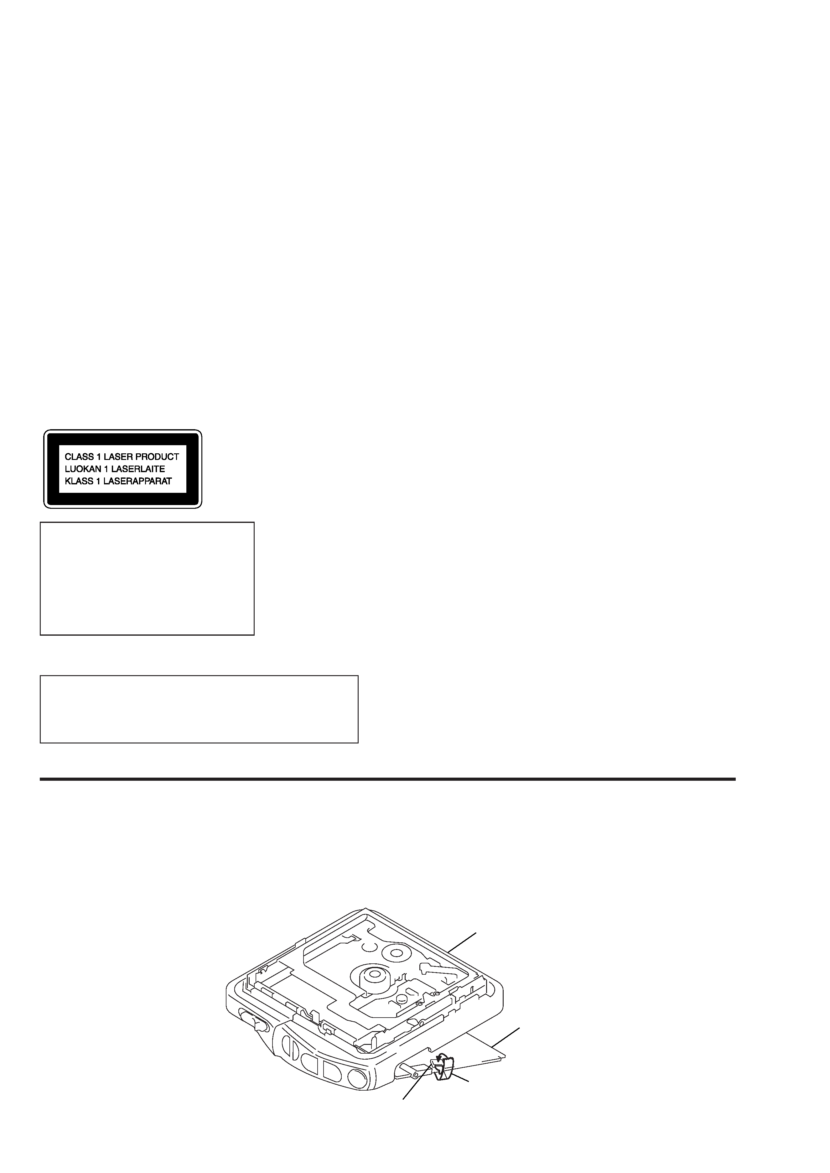
This Mini Disc player is classi-
fied as a CLASS 1 LASER
product.
The CLASS 1 LASER
PRODUCT label is located on
the bottom exterior.
5. ELECTRICAL ADJUSTMENTS ............................ 10
6. DIAGRAMS
6-1. Explanation of IC Terminals ..................................... 13
6-2. Block Diagram .......................................................... 15
6-3. Printed Wiring Boards .............................................. 18
6-4. Schematic Diagram ................................................... 21
7. EXPLODED VIEWS
7-1. Panel Section ............................................................ 28
7-2. Main Section ............................................................. 29
7-3. Mechanism Deck Section ......................................... 30
8. ELECTRICAL PARTS LIST ................................ 31
SECTION 1
SERVICING NOTE
When repairing this device with the power on, if you remove the main board, this device stops working.
In this case, you work without the device stopping by fastening the hook of the Open/Close detection switch (S801) with tape.
Chassis ASSY
Main board
Tape
Open/Close switch (S801)
3
SECTION 2
GENERAL
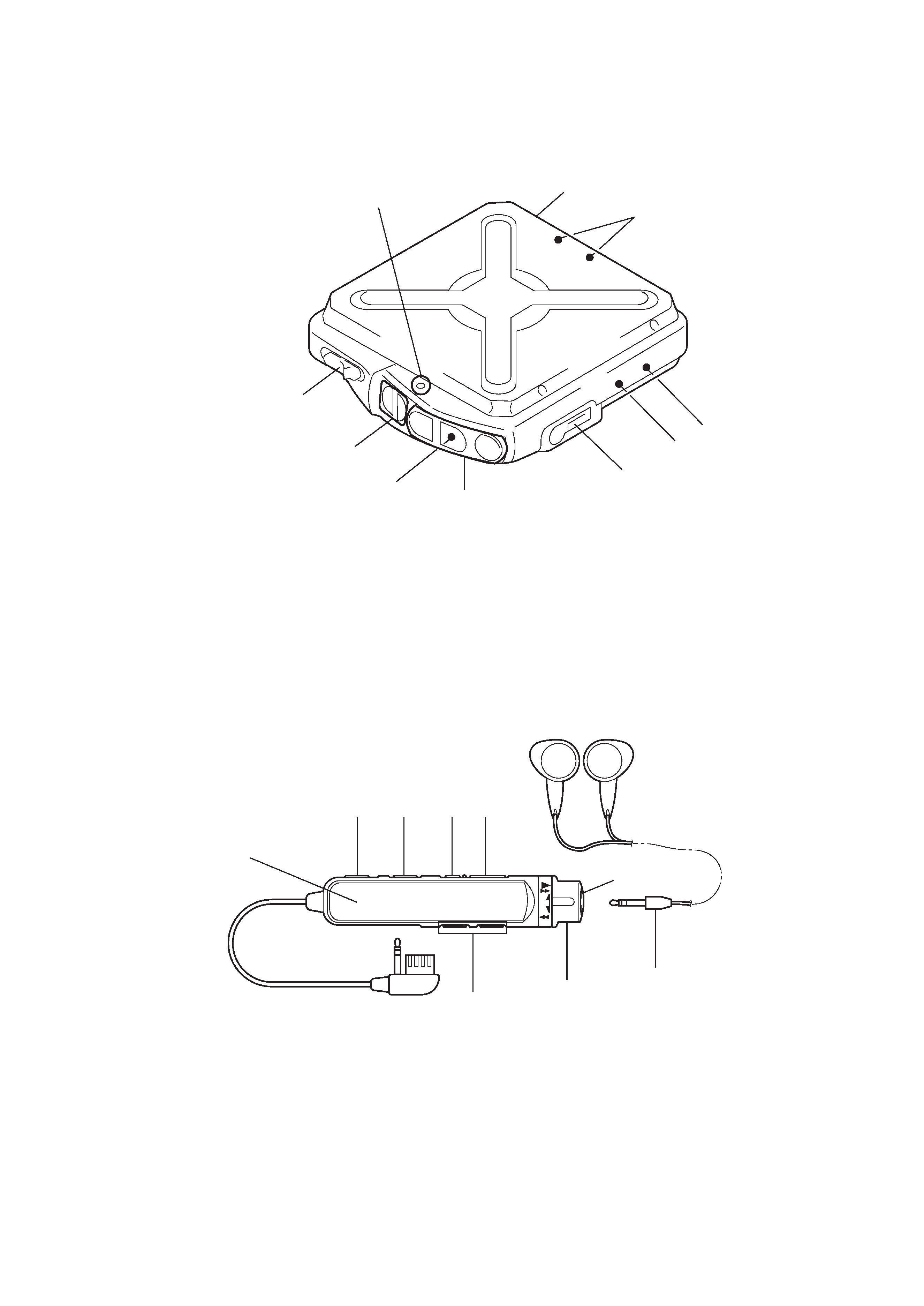
LOCATION AND FUNCTION OF CONTROLS
Headphones with Remote Control
2
7
6
3
1
5
4
8
!º
9
1
2
3
4
5
6
8
9
7
Main Unit
1 MDoperatebuttons
" · + (PLAY · FF )
= (REW )
p(STOP)
2 HOLDswitch
3 VOLUME+/buttons
4 EJECTbutton
5 OPERA TElamp
6 Batterycompartment
7 Externalbatteryterminal(+/)
8 DIGITAL MEGA BASS s witc h
9 AVLSs witc h
!º 2/ REMOTE jack
1 Headphones
2 MDoperateswitchandbuttons
" · + (PLAY · FF)
= (REW)
p(STOP)
3 VOL+/button
4 Displayindicator
5 DISPLAYbutton
6 PLAYMODEbutton
7 P(PAUSE)b utton
8 HOLD cswitch
9 p(STOP)b utton
4
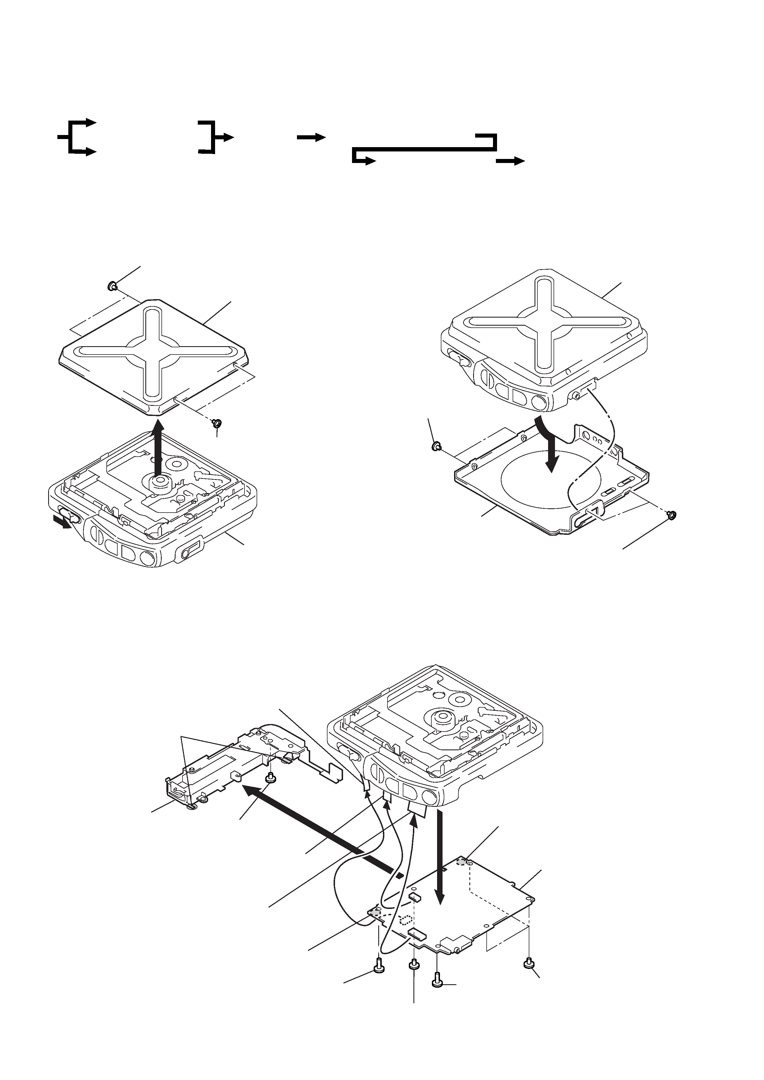
SECTION 3
DISASSEMBLY
Note : Follow the disassembly procedure in the numerical order given.
3-1. UPPER PANEL ASSY
3-3. MAIN BOARD
r
The equipment can be removed using the following procedure.
3-2. BOTTOM PANEL ASSY
1
3
2 Screws (M1.4) pan precision
Upper panel ASSY
Main section
2 Screws (M1.4) pan precision
2
1 Screws (M1.4)
pan precision
Bottom panel ASSY
Main section
1 Screws (M1.4) pan precision
7
!º
4 Switch unit (CN801)
9 Remove solder
9 Remove solder
9 Remove solder
1 Screw (M1.4x2)
toothed lock
8 Screw tapping (M1.7)
1 Screws (M1.4x2)
toothed lock
2 Screw
Main board
Battery case ASSY
6 Flexible (CLV)
board (CN551)
5 Flexible board
(CN501)
3 Screw (M1.4)
pan precision
set
Main board
Belt ASSY, Front panel ASSY
Mechanism deck section
Optical pick-up block ASSY
Upper panel ASSY
Bottom panel ASSY
5
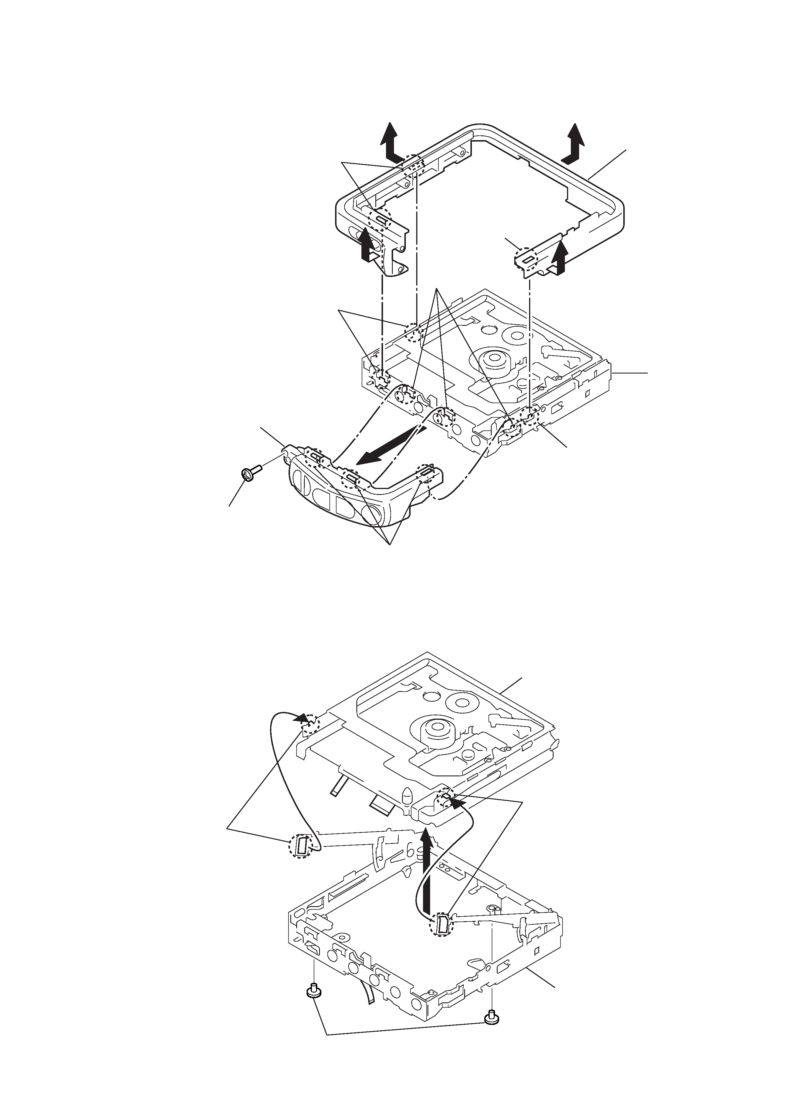
3-4. BELT ASSY, FRONT PANEL ASSY
3-5. MECHANISM DECK SECTION
32
1
8
4
Boss
Boss
Main section
5 Belt ASSY
7 Claws
Claw
Boss
Claws
Front panel ASSY
6 Screw
(M1.4) pan precision
3
1 Remove claws
1 Remove claws
2 Step screws
Chassis ASSY (main section)
Mechanism deck section