MZ-E33
SERVICE MANUAL
PORTABLE MINIDISC PLAYER
SPECIFICATIONS
E Model
Model Name Using Similar Mechanism
MZ-E55
MD Mechanism Type
MT-MZE55-150
Optical Pick-up Mechanism Type
ODX-1A/1B
US and foreign patents licensed from Dolby
Laboratories Licensing Corporation.
System
Audio playing system
MiniDisc digital audio system
Laser diode properties
Material : GaAlAs
Wavelength :
=790 nm
Emission duration : continuous
Laser output : less than 44.6
µW*
* This output is the value measured at a distance of 200 mm from the
objective lens surface on the optical pick-up block with 7 mm aperture.
Revolutions
400 rpm to 900 rpm (CLV)
Error correction
Advanced Cross Interleave Reed Solomon Code (ACIRC)
Sampling frequency
44.1kHz
Coding
Adaptive TRansform Acoustic Coding (ATRAC)
Modulation system
EFM (Eight to Fourteen Modulation)
Number of channels
2 stereo channels
1 monaural channel
Frequency response
20 to 20,000 Hz
± 3 dB
Wow and Flutter
Below measurable limit
Outputs
Headphones : stereo mini-jack, maximum output level 5mW+5mW,
load impedance 16 ohm
General
Power requirements
One LR6 (size AA) alkaline battery (not supplied)
Ni-MH rechargeable battery NH-9WM/NH-14WM
(not supplied)
R-6 sized Ni-MH rechargeable battery NH-MDAA (supplied)
Sony AC Power Adaptor AC-MZR55 (supplied) connected at the
DC IN 3V jack
Battery operation time
Batteries
Playback
LR6 (SG) (size AA)
Approx. 9.5 hours
Sony alkaline battery
R-6 sized Ni-MH
Approx. 8 hours
rechargeable battery
NH-MDAA
Chewing gum type
Approx. 7 hours
Ni-MH rechargeable
battery NH-14WM
Chewing gum type
Approx. 6.5 hours
Ni-MH rechargeable
battery NH-9WM (N)
Dimensions
Approx. 80
× 17.3 × 92 mm (w/h/d)
(3 1/4
× 11/16 × 3 5/8 in.)
not including projecting parts and controls
MICROFILM
Continued on next page
Ver 1.0 1998. 10
2
1. SERVICING NOTE ....................................................... 3
2. GENERAL ....................................................................... 4
3. DISASSEMBLY
3-1. Bottom Panel Assy .............................................................. 5
3-2. Upper Panel Assy ................................................................ 5
3-3. Main Board ......................................................................... 6
3-4. MD Assy ............................................................................. 6
3-5. OP Service Assy .................................................................. 6
4. TEST MODE ................................................................... 7
5. ELECTRICAL ADJUSTMENTS ............................ 11
6. DIAGRAMS
6-1. IC Pin Description ............................................................. 13
6-2. Block Diagram .................................................................. 15
6-3. Printed Wiring Board ........................................................ 18
6-4. Schematic Diagram ........................................................... 21
7. EXPLODED VIEWS
7-1. Panel Section ..................................................................... 29
7-2. Main Board Section .......................................................... 30
7-3. Mechanism Deck Section .................................................. 31
8. ELECTRICAL PARTS LIST .................................... 32
TABLE OF CONTENTS
SAFETY-RELATED COMPONENT WARNING!!
COMPONENTS IDENTIFIED BY MARK
! OR DOTTED LINE WITH
MARK
! ON THE SCHEMATIC DIAGRAMS AND IN THE PARTS
LIST ARE CRITICAL TO SAFE OPERATION.
REPLACE THESE COMPONENTS WITH SONY PARTS WHOSE
PART NUMBERS APPEAR AS SHOWN IN THIS MANUAL OR IN
SUPPLEMENTS PUBLISHED BY SONY.
Flexible Circuit Board Repairing
· Keep the temperature of the soldering iron around 270
°C during
repairing.
· Do not touch the soldering iron on the same conductor of the
circuit board (within 3 times).
· Be careful not to apply force on the conductor when soldering
or unsoldering.
Notes on chip component replacement
· Never reuse a disconnected chip component.
· Notice that the minus side of a tantalum capacitor may be dam-
aged by heat.
CAUTION
Use of controls or adjustments or performance of procedures
other than those specified herein may result in hazardous
radiation exposure.
IN NO EVENT SHALL SELLER BE
LIABLE FOR ANY DIRECT,
INCIDENTAL OR CONSEQUENTIAL
DAMAGES OF ANY NATURE, OR
LOSSES OR EXPENSES RESULTING
FROM ANY DEFECTIVE PRODUCT
OR THE USE OF ANY PRODUCT.
"MD WALKMAN" is a trademark of Sony
Corporation.
This MiniDisc player is classi-
fied as a CLASS 1 LASER
product.
The CLASS 1 LASER
PRODUCT label is located on
the bottom exterior.
Mass
Approx. 113 g (4.0 oz.) the player only
Approx. 155 g (5.5 oz.) incl. a premastered MD and a Sony
alkaline LR6 (SG) battery
Supplied accessories
AC power adaptor AC-MZR55 (1)
R-6 sized Ni-MH rechargeable battery NH-MDAA (1)
Rechargeable battery carrying case (1)
Headphones with a remote control MDR-E838SP + RM-MZE33 (1)
Carrying pouch (1)
Design and specifications are subject to change without notice.
3
SECTION 1
SERVICING NOTE
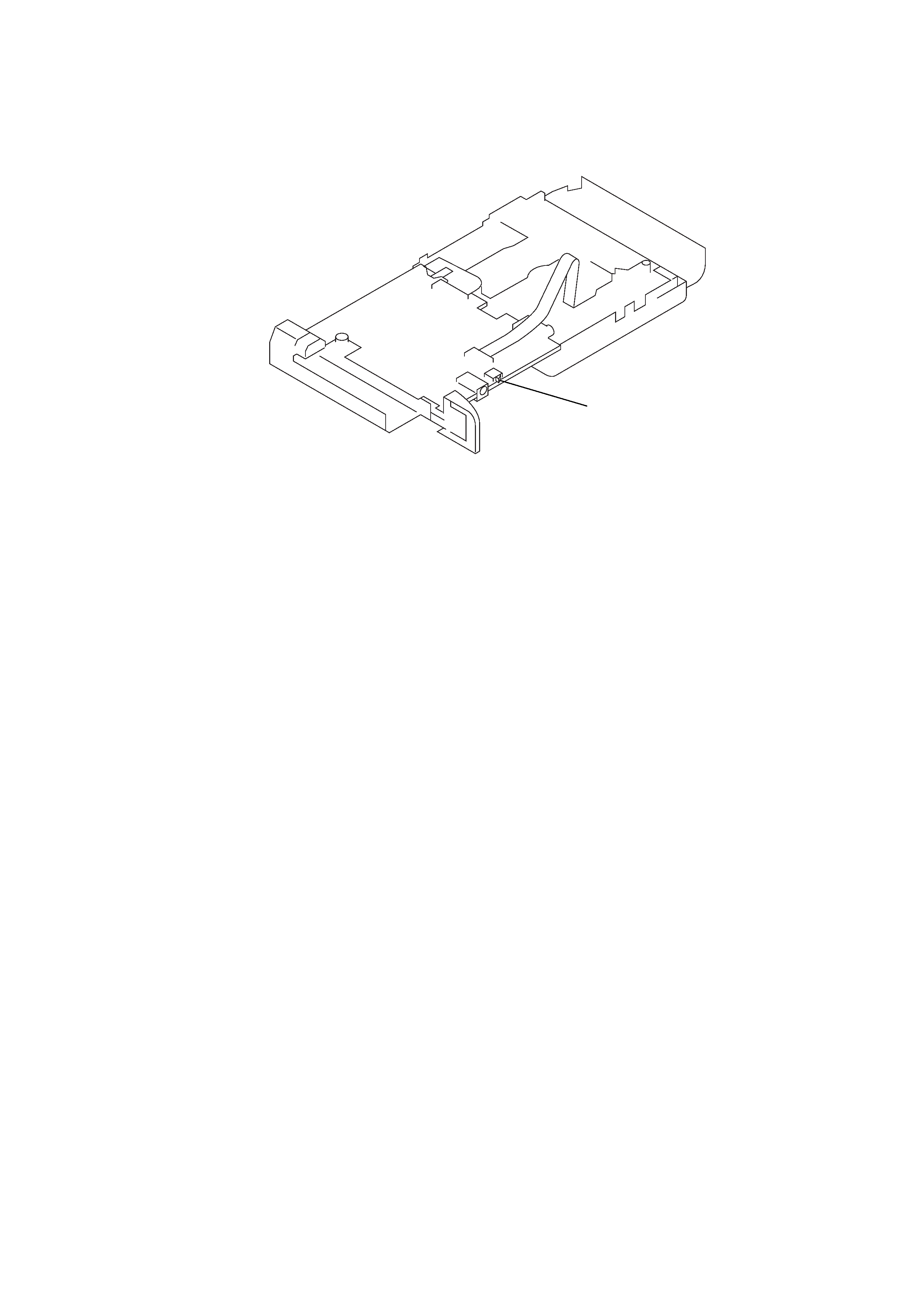
1. Whenrepairingthisde
vicewiththepo
weron, ifyouremo vethemainboar
d, thisde vicestopsw
orking.
Inthiscase ,youw orkwithoutthede
vicestoppingb
yfasteningthehookoftheDOOROPEN/CLOSEs
witc h(S801)withtape
.
S801
2. Theelectricalcomponentsdiff
eraccor dingtothever
sionofthesystemcontr
olIC(IC801). WhenreplacingtheIC801,
chec kitsmodel
nameandad
dorremo veD1001and/orR1001assho
wnbelo w.Fordetailedinf
ormation, seethePrinted
WiringBoar donpa ge18and
theSchematicDiagramonpage21.
RU6815MF-0003 (V er. 2.0) .... Ad d D1001
RU6815MF-0004 (V er. 3.0) .... Ad d D1001 and R1001
RU6815MF-0005 (V er.3.2) and later ....
Remo ve D1001 and R1001
4
SECTION 2
GENERAL
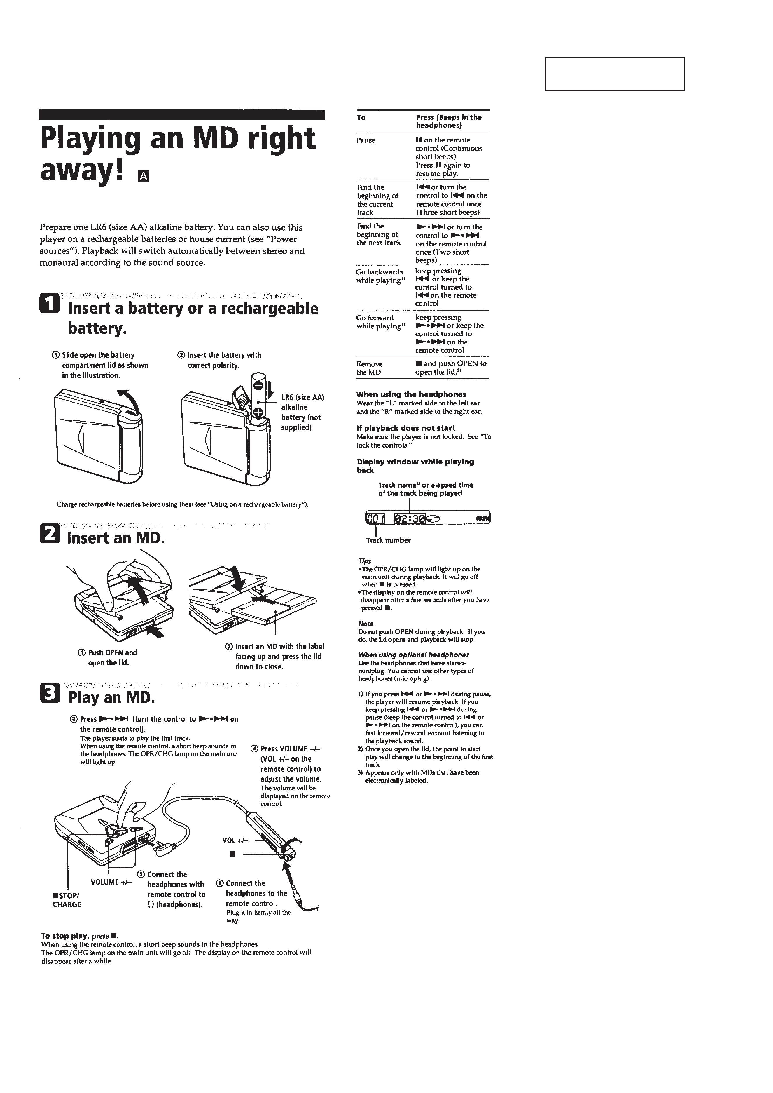
This section is extracted
from instruction manual.
5
SECTION 3
DISASSEMBLY
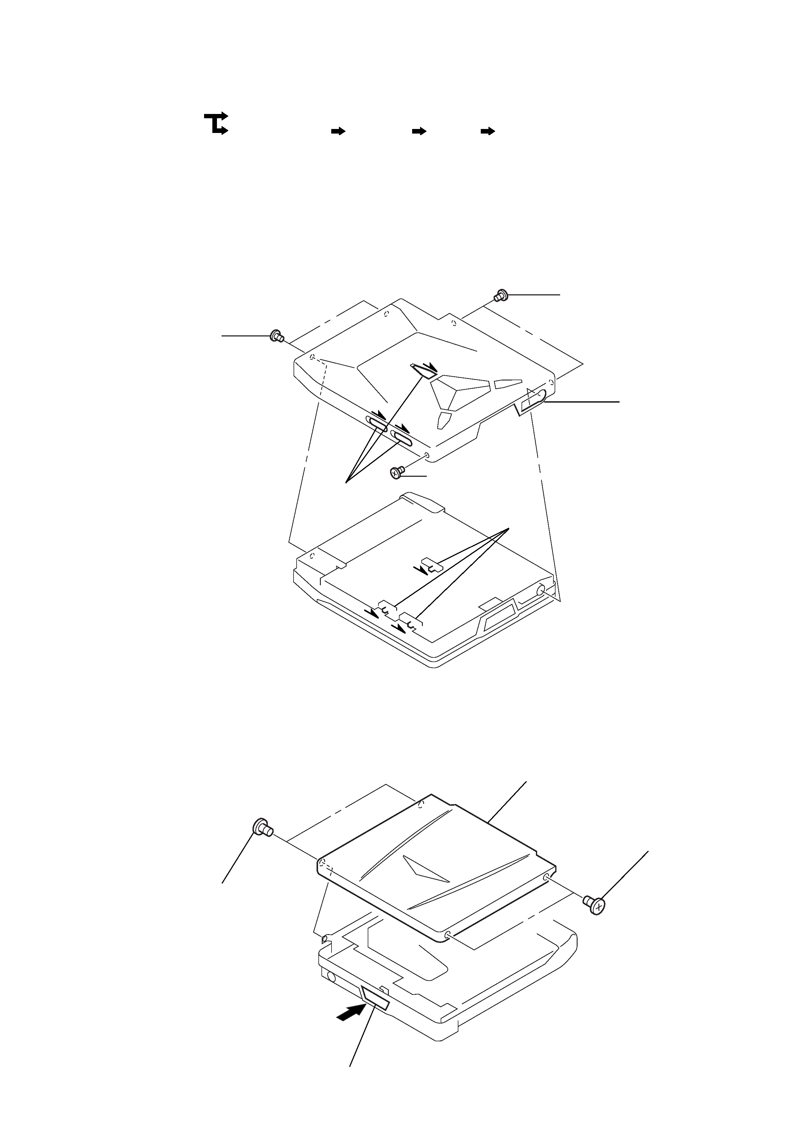
3-1. BOTTOM PANEL ASSY
Note : When installing, fit the knobs and switches.
3-2. UPPER PANEL ASSY
· The equipment can be removed using the following procedure.
Bottom panel assy
Main board
Upper panel assy
Main board
MD assy
OP service assy
Note : Follow the disassembly procedure in the numerical order given.
1 precision pan
screw (M1.4)
2 precision pan
screw (M1.4)
3 precision pan
screw (M1.4)
4 bottom panel assy
knobs
switches
2 precision pan
screw (M1.4)
4 upper panel assy
3 precision pan
screw (M1.4)
1 button (OPEN)