Ver 1.2 2001.12
MZ-E300
SERVICE MANUAL
PORTABLE MINIDISC PLAYER
SPECIFICATIONS
US Model
Canadian Model
AEP Model
E Model
Chinese Model
Model Name Using Similar Mechanism
NEW
MD Mechanism Type
MT-MZE300-176
Optical Pick-up Mechanism Type
LCX-4E
US and foreign patents licensed from Dolby
Laboratories Licensing Corporation
System
Audio playing system
MiniDisc digital audio system
Laser diode properties
Material: GaAlAs
Wavelength:
= 790 nm
Emission duration: continuous
Laser output: less than 44.6
µW*
* This output is the value measured at a distance of 200 mm from
the objective lens surface on the optical pick-up block with 7 mm
aperture.
Revolutions
Approx. 700 rpm to 1,500 rpm
Error correction
ACIRC (Advanced Cross Interleave Reed Solomon Code)
Sampling frequency
44.1 kHz
Coding
ATRAC (Adaptive TRansform Acoustic Coding)
Modulation system
EFM (Eight to Fourteen Modulation)
Number of channels
2 stereo channels
1 monaural channel
Frequency response
20 to 20,000 Hz
± 3 dB
Wow and Flutter
Below measurable limits
Power requirements
One LR6 (size AA) battery (not supplied)
Battery operation time
Battery life
(EIAJ1))
Battery
Playback
LR6 (SG) Sony Alkaline dry battery 2)
Approx. 33 hours
1) Measured in accordance with the EIAJ (Electronic Industries
Association of Japan) standard (using a Sony MDW-series Mini-disc).
2) When using a Sony LR6 (SG) "STAMINA" alkaline dry battery
(produced in Japan).
Note
The effective battery life may be shorter than that indicated above,
depending on operating conditions, the surrounding temperature, and
the battery type.
Dimensions
Approx. 83.0 x 26.7 x 76.5 mm (w/h/d) (3 3/8 x 1 1/16 x 3 1/8 in.)
(not including projecting parts and controls)
Mass
Approx. 83.0 g (3.0 oz) (the player only)
Supplied accessories
Headphones/earphones (1)
Design and specifications are subject to change without notice.
9-873-064-13
2001L0200-1
© 2001.12
Sony Corporation
Personal Audio Company
Published by Sony Engineering Corporation
2
MZ-E300
Specifications ........................................................................... 1
1. SERVICING NOTE ...................................................... 2
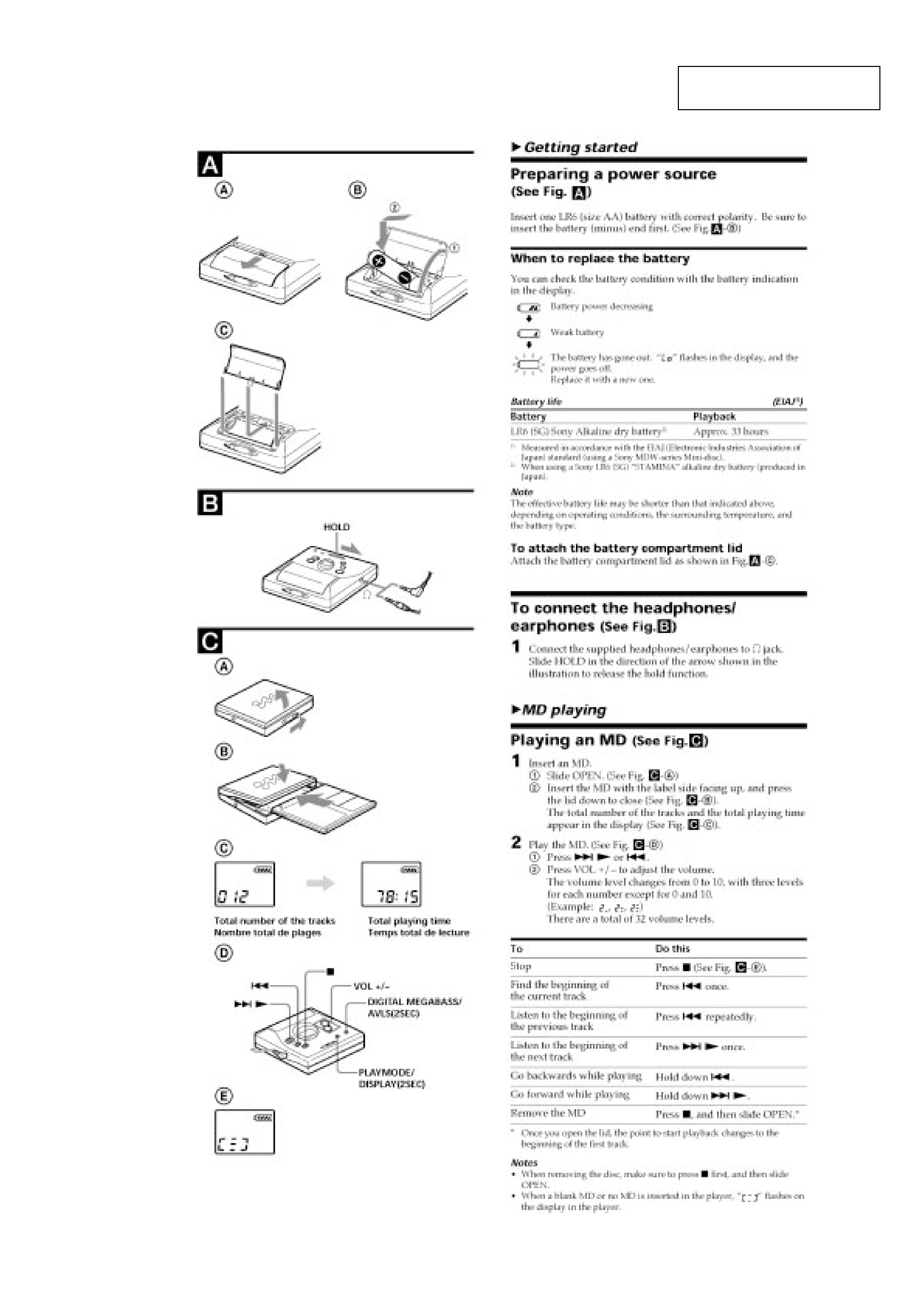
2. GENERAL
Preparing a Power Source .................................................. 3
To Connect the Headphones/Earphones ............................ 3
Playing an MD ................................................................... 3
3. DISASSEMBLY
3-1. "Lid ASSY, Upper", Holder ASSY ............................ 4
3-2. Mechanism Deck ........................................................ 4
3-3. Main Board ................................................................. 5
3-4. Optical Pick-up ASSY ................................................ 5
4. TEST MODE .................................................................. 6
5. DIAGRAMS
5-1. Explanation of IC Terminals ..................................... 13
5-2. Block Diagram .......................................................... 18
5-3. Printed Wiring Boards Main Section (1/2) ......... 19
5-4. Printed Wiring Boards Main Section (2/2) ......... 20
5-5. Schematic Diagram Main Section (1/3) ............. 21
5-6. Schematic Diagram Main Section (2/3) ............. 22
5-7. Schematic Diagram Main Section (3/3) ............. 23
6. EXPLODED VIEWS
6-1. Main Section ............................................................. 29
6-2. Mechanism Deck Section ......................................... 30
7. ELECTRICAL PARTS LIST ................................... 31
SAFETY-RELATED COMPONENT WARNING!!
COMPONENTS IDENTIFIED BY MARK 0 OR DOTTED LINE
WITH MARK 0 ON THE SCHEMATIC DIAGRAMS AND IN THE
PARTS LIST ARE CRITICAL TO SAFE OPERATION.
REPLACE THESE COMPONENTS WITH SONY PARTS WHOSE
PART NUMBERS APPEAR AS SHOWN IN THIS MANUAL OR IN
SUPPLEMENTS PUBLISHED BY SONY.
Flexible Circuit Board Repairing
· Keep the temperature of the soldering iron around 270
°C during
repairing.
· Do not touch the soldering iron on the same conductor of the
circuit board (within 3 times).
· Be careful not to apply force on the conductor when soldering or
unsoldering.
Notes on chip component replacement
· Never reuse a disconnected chip component.
· Notice that the minus side of a tantalum capacitor may be dam-
aged by heat.
TABLE OF CONTENTS
SECTION 1
SERVICING NOTE
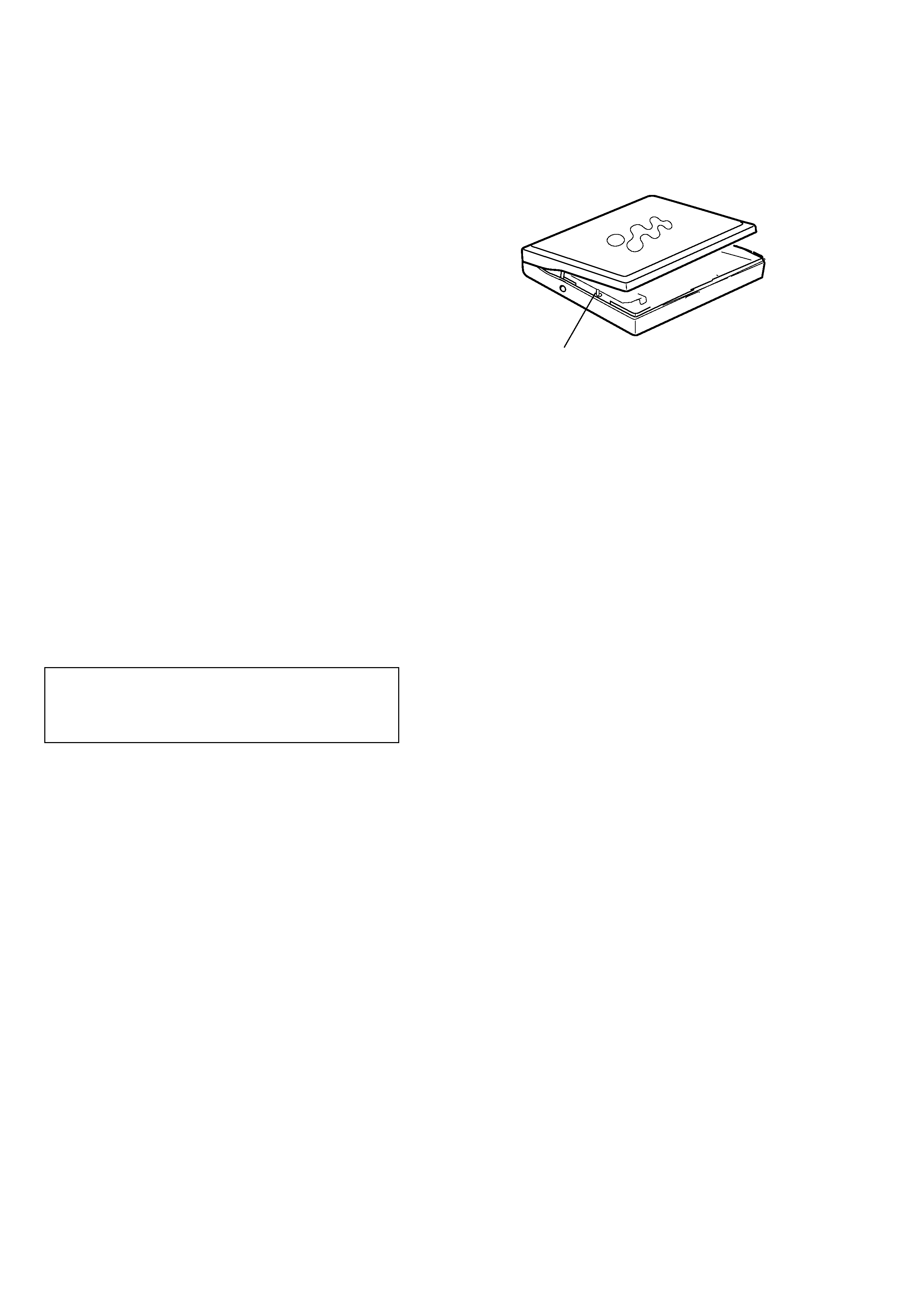
When repairing this device with the power on, if you remove the
main board, this device stops working.
In this case, you work without the device stopping by fastening
the hook of the Open/Close detection switch (S808).
CAUTION
Use of controls or adjustments or performance of procedures
other than those specified herein may result in hazardous
radiation exposure.
Open/Close detection switch (S808)
Note on IC replacement
If using flux on replacing IC801 etc., clean it with alcohol or
equivalent, and after that, check carefully there are no dust or
rags in between pins.
ATTENTION AU COMPOSANT AYANT RAPPORT
À LA SÉCURITÉ!
LES COMPOSANTS IDENTIFIÉS PAR UNE MARQUE 0 SUR LES
DIAGRAMMES SCHÉMATIQUES ET LA LISTE DES PIÈCES
SONT CRITIQUES POUR LA SÉCURITÉ DE FONCTIONNEMENT.
NE REMPLACER CES COMPOSANTS QUE PAR DES PIÈCES
SONY DONT LES NUMÉROS SONT DONNÉS DANS CE MANUEL
OU DANS LES SUPPLÉMENTS PUBLIÉS PAR SONY.
Especially, be sure to check between pins 4 and 5.
3
MZ-E300
SECTION 2
GENERAL
This section is extracted from
instruction manual.
4
MZ-E300
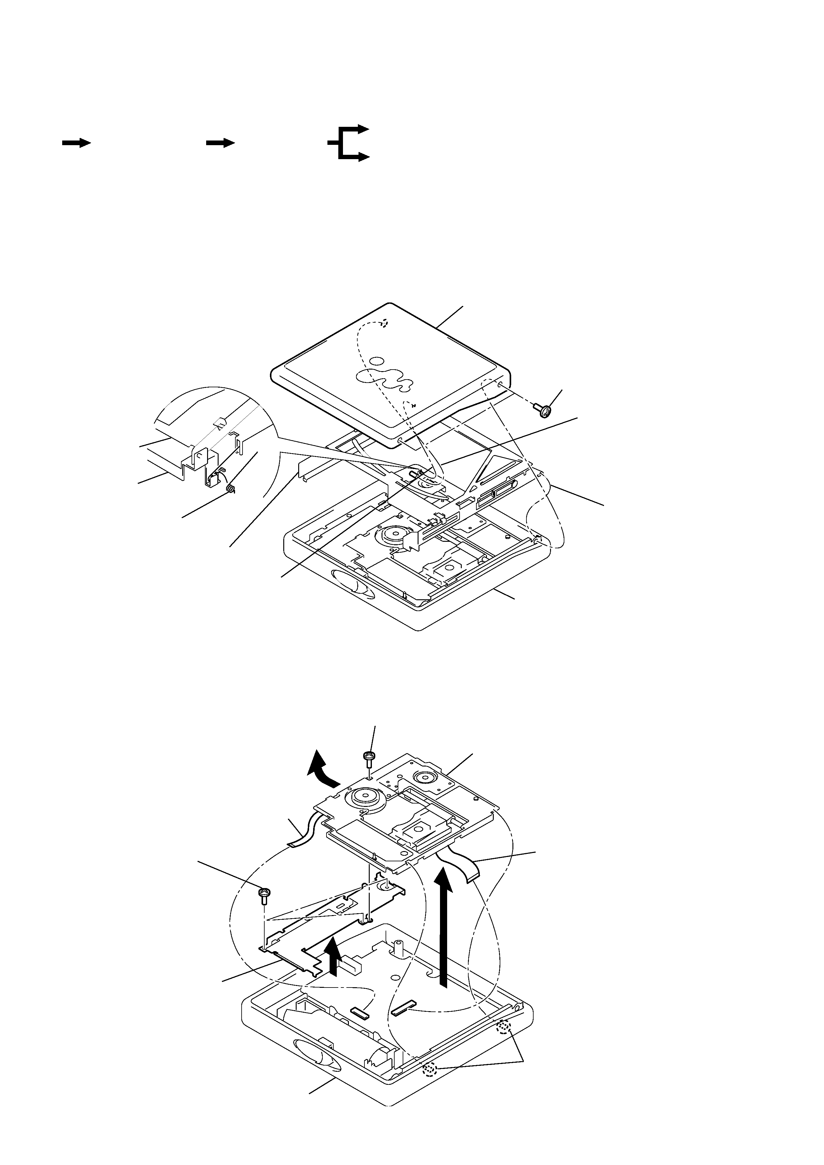
SECTION 3
DISASSEMBLY
Note : Follow the disassembly procedure in the numerical order given.
3-1. "LID ASSY, UPPER", HOLDER ASSY
3-2. MECHANISM DECK
· The equipment can be removed using the following procedure.
1
Screws (1.4),MI
Case ASSY
3
Lid ASSY , Upper
5
Holder ASSY
Holder ASSY
Reinforcement
Spring (POP/L)
4
Move it away
from projection
4
Move it away
from projection
2
Move it away
from projection
7
Screws, tapping (1.7)
Case ASSY
Mechanism deck
Reinforcement
3
Claw
2
4
8
1
Screw (MD), step
5
Motor flexible board
6
OP flexible board
Optical pick-up ASSY
Set
"Lid ASSY, Upper",
Holder ASSY
Mechanism deck
Main board
Note :
Holder ASSY installation
1. Attach the holes on Holder ASSY to the projections on right and left sides.
2. Attach Spring (POP/L) as shown in the figure.
5
MZ-E300
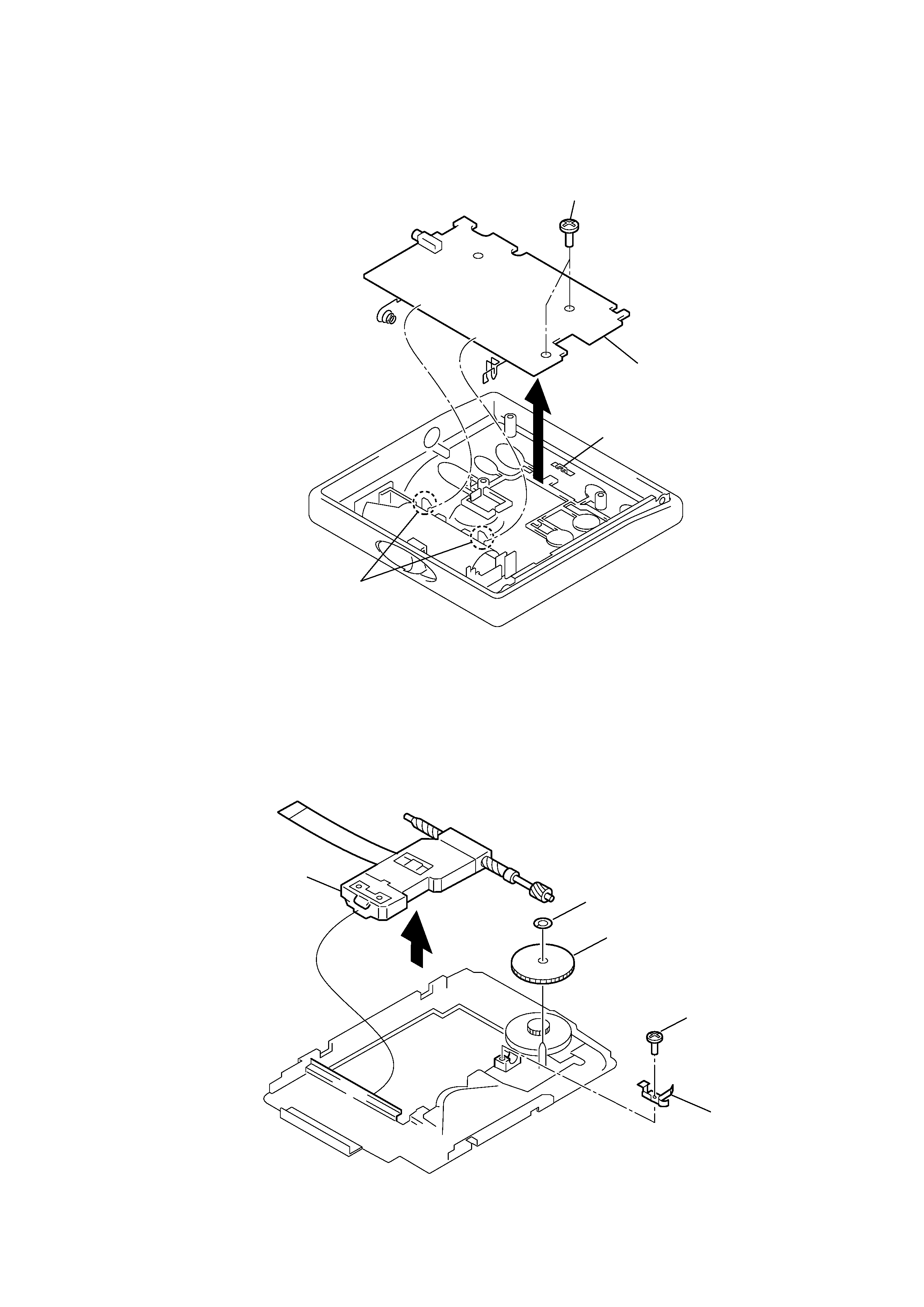
3-3. MAIN BOARD
3-4. OPTICAL PICK-UP ASSY
1
Screws, tapping (1.7)
2
Claw
3
Main board
Knob (HOLD)
3
Screw (MI 1.4)
4
Spring, thrust detent
1
Washer
2
Gear (SA)
5
Optical pick-up ASSY
(LCX-4E)
Note :
On installation of main board, adjust the position of
both switch (S809) and knob (HOLD).