SERVICE MANUAL
PORTABLE MD PLAYER
US Model
Canadian Model
SPECIFICATIONS
MZ-DH710
Ver. 1.0 2005.04
Model Name Using Similar Mechanism
NEW
MD Mechanism Type
MT-MZNH900-181
Optical Pick-up Name
ABX-U
9-879-660-01
2005D05-1
© 2005.04
Sony Corporation
Personal Audio Group
Published by Sony Engineering Corporation
Continued on next page
US and foreign patents licensed from Dolby Laboratories.
· SonicStage and SonicStage logo are trademarks or registered trademarks
of Sony Corporation.
· MD Simple Burner, OpenMG, "Magic Gate", "MagicGate Memory
Stick", "Memory Stick", Hi-MD, Net MD, ATRAC, ATRAC3,
ATRAC3plus and their logos are trademarks of Sony Corporation.
· Microsoft, Windows, Windows NT and Windows Media are trademarks
or registered trademarks of Microsoft Corporation in the United States
and /or other countries.
· IBM and PC/AT are registered trademarks of International Business
Machines Corporation.
· Macintosh is a trademark of Apple Computer, Inc. in the United States
and/or other countries.
·Pentium is a trademark or registered trademark of Intel Corporation.
· All other trademarks and registered trademarks are trademarks or
registered trademarks of their respective holders.
·TM and ® marks are omitted in this manual.
· CD and music-related data from Gracenote, Inc., copyright © 2000-2004
Gracenote. Gracenote CDDB® Client Software, copyright 2000-2004
Gracenote. This product and service may practice one or more of the
following U.S. Patents: #5,987,525; #6,061,680; #6,154,773, #6,161,132,
#6,230,192, #6,230,207, #6,240,459, #6,330,593, and other patents issued
or pending. Services supplied and/or device manufactured under license
for following Open Globe, Inc. United States Patent 6,304,523. Gracenote
is a registered trademarks of Gracenote. The Gracenote logo and logotype,
and the "Powered by Gracenote" logo are trademarks of Gracenote.
Program © 2001, 2002, 2003, 2004, 2005 Sony Corporation
Documentation © 2005 Sony Corporation
Audio playing system
MiniDisc digital audio system
Laser diode properties
Material: GaAlAs
Wavelength:
= 790 nm
Emission duration: continuous
Laser output: less than 44.6
µW
(This output is the value measured at a distance
2
MZ-DH710
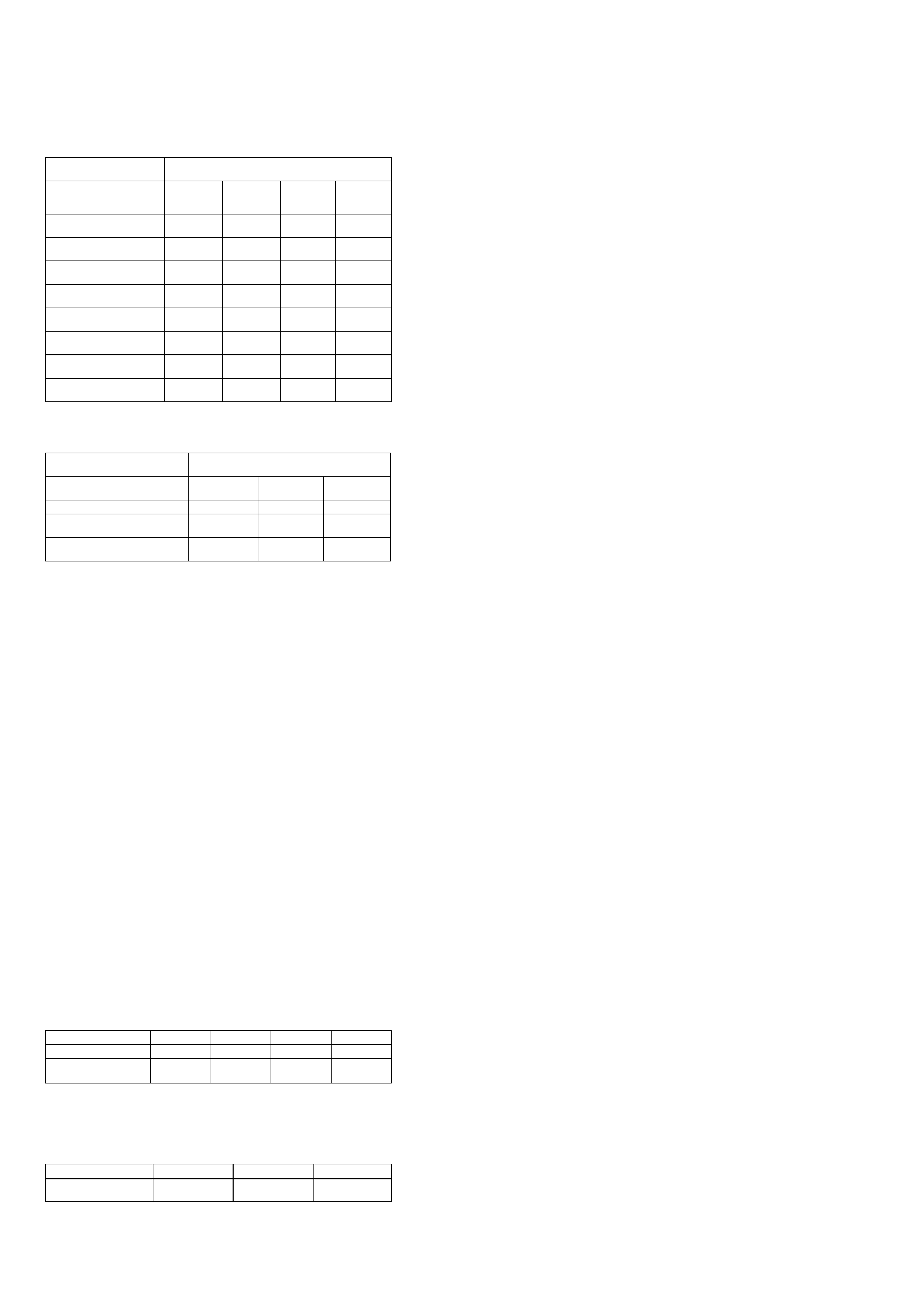
Recording and playback time
List of the recording time for each disc
When using a disc in Hi-MD mode
When using a disc in MD mode
When transferring from
the computer
Recording time1)2)
1) Approximate time
2) When transferring 4-minute tracks
Codec/Bit rate
1GB Hi-MD
disc
80-minute
standard
disc
74-minute
standard
disc
60-minute
standard
disc
Linear PCM/1.4Mbps
1 hour and
34 minutes
28 minutes
26 minutes
21 minutes
ATRAC3plus/256kbps
7 hours and
55 minutes
2 hours and
20 minutes
2 hours and
10 minutes
1 hour and
40 minutes
ATRAC3plus/64kbps
34 hours
10 hours and
10 minutes
9 hours and
20 minutes
7 hours and
40 minutes
ATRAC3plus/ 48 kbps
45 hours
13 hours and
30 minutes
12 hours and
30 minutes
10 hours
ATRAC3/132kbps
16 hours and
30 minutes
4 hours and
50 minutes
4 hours and
30 minutes
3 hours and
40 minutes
ATRAC3/105kbps
20 hours and
40 minutes
6 hours and
10 minutes
5 hours and
40 minutes
4 hours and
40 minutes
ATRAC3/66kbps
32 hours and
40 minutes
9 hours and
50 minutes
9 hours
7 hours and
20 minutes
MP3/128kbps
17 hours
5 hours
4 hours and
30 minutes
3 hours and
30 minutes
When transferring from the
computer
Recording time1)2)
1) Approximate time
2) When transferring 4-minute tracks
Codec/Bit rate
80-minute
standard disc
74-minute
standard disc
60-minute
standard disc
ATRAC(stereo)/292kbps
80 minutes
74 minutes
60 minutes
ATRAC3/132, 105kbps
2 hours and
40 minutes
2 hours and
28 minutes
2 hours
ATRAC3/66kbps
5 hours and
20 minutes
4 hours and
56 minutes
4 hours
Dimensions
Approx. 83.6
× 29.5 × 77.0 mm (w/h/d)
(33/8
× 13/16 × 31/8 in.)(excluding projecting
parts and controls)
Mass
Approx
Supplied accessories
Earphones
Dedicated USB cable
CD-ROM (SonicStage/MD Simple Burner)*
Recordable disc
* Do not play a CD-ROM on an audio CD player.
. 107 g (3.8 oz.) (the player only)
Design and specifications are subject to change
without notice.
Revolutions
350 rpm to 3,000 rpm (CLV)
Error correction
Hi-MD:
LDC (Long Distance Code)/BIS (Burst
Indicator Subcode)
MD:
ACIRC (Advanced Cross Interleave Reed
Solomon Code)
Sampling frequency
44.1 kHz
Audio formats supported by this
player
Linear PCM (44.1 kHz/16 bit)
ATRAC3plus (Adaptive TRansform Acoustic
Coding 3 plus)
AT RAC3
AT RAC
MP3 (MPEG-1 Audio Layer-3/Sampling
frequency 44.1 kHz/Bit rate 32 - 320 kbps
(constant/variable bit rate))
Modulation system
Hi-MD:
1-7RLL (Run Length Limited)/PRML
(Partial Response Maximum Likelihood)
MD:
EFM (Eight to Fourteen Modulation)
Frequency response
20 to 20,000 Hz
± 3 dB
Outputs
i
: stereo mini-jack
Maximum output (DC)
Headphones:
5 mW + 5 mW (16
)
Power requirements
One LR6 (size AA) alkaline battery (not
supplied)
Operating temperature
+5
°C (+41°F) to +35°C (+95°F)
Battery operation time
When playing continuously in MD mode
(Unit: approx. hours) (JEITA)
Battery life1)
When playing continuously in Hi-MD mode
(Unit: approx. hours) (JEITA2))
1) When using a new Sony LR6 (size AA) alkaline dry battery (produced in Japan)
2) Measured in accordance with the JEITA (Japan Electronics and Information Technology Industries
Association) standard.
Disc type
Linear PCM
Hi-SP
Hi-LP
MP33)
3) Tracks transferred at 128 kbps.
1GB Hi-MD disc
9.5
16.5
19.5
19.0
60/74/80-minute
standard disc
8.5
16.0
19.0
18.5
Disc type
SP
LP2
LP4
60/74/80-minute
standard disc
18.0
21.5
23.5

3
MZ-DH710
Notes on chip component replacement
· Never reuse a disconnected chip component.
· Notice that the minus side of a tantalum capacitor may be
damaged by heat.
Flexible Circuit Board Repairing
· Keep the temperature of the soldering iron around 270 °C
during repairing.
· Do not touch the soldering iron on the same conductor of the
circuit board (within 3 times).
· Be careful not to apply force on the conductor when soldering
or unsoldering.
CAUTION
Use of controls or adjustments or performance of procedures
other than those specified herein may result in hazardous radiation
exposure.
SAFETY-RELATED COMPONENT WARNING!!
COMPONENTS IDENTIFIED BY MARK 0 OR DOTTED LINE
WITH MARK 0 ON THE SCHEMATIC DIAGRAMS AND IN
THE PARTS LIST ARE CRITICAL TO SAFE OPERATION.
REPLACE THESE COMPONENTS WITH SONY PARTS WHOSE
PART NUMBERS APPEAR AS SHOWN IN THIS MANUAL OR
IN SUPPLEMENTS PUBLISHED BY SONY.
TABLE OF CONTENTS
1.
SERVICING NOTES ............................................... 4
2.
GENERAL ................................................................... 5
3.
DISASSEMBLY
3-1.
Disassembly Flow ...........................................................
6
3-2.
Case (Lower) Section ......................................................
7
3-3.
MAIN Board ....................................................................
7
3-4.
Case (Upper) Section .......................................................
8
3-5.
Mechanism Deck Section (MT-MZNH900-181),
MD Standard Pin .............................................................
8
3-6.
Set Chassis Assy ..............................................................
9
3-7.
Gear (BSA), Gear (SB) ...................................................
9
3-8.
OP Service Assy .............................................................. 10
3-9.
DC Motor SSM18D/C-NP (Spindle) (M701),
DC Motor (Sled) (M702),
DC Motor Unit (Over Write Head Up/Down) (M703) ... 10
3-10. Holder Assy ..................................................................... 11
3-11. Position of Ferrite Core ................................................... 11
4.
TEST MODE .............................................................. 12
5.
ELECTRICAL ADJUSTMENTS .......................... 16
6.
DIAGRAMS
6-1.
Block Diagram MD SERVO Section ........................ 21
6-2.
Block Diagram POWER SUPPLY Section ............... 22
6-3.
Printed Wiring Board MAIN Section (1/2) ............... 24
6-4.
Printed Wiring Board MAIN Section (2/2) ............... 25
6-5.
Schematic Diagram MAIN Section (1/8) .................. 26
6-6.
Schematic Diagram MAIN Section (2/8) .................. 27
6-7.
Schematic Diagram MAIN Section (3/8) .................. 28
6-8.
Schematic Diagram MAIN Section (4/8) .................. 29
6-9.
Schematic Diagram MAIN Section (5/8) .................. 30
6-10. Schematic Diagram MAIN Section (6/8) .................. 31
6-11. Schematic Diagram MAIN Section (7/8) .................. 32
6-12. Schematic Diagram MAIN Section (8/8) .................. 33
7.
EXPLODED VIEWS
7-1.
Case (Lower) Section ...................................................... 44
7-2.
Case (Upper) Section ....................................................... 45
7-3.
Chassis Section ................................................................ 46
7-4.
Mechanism Deck Section (MT-MZNH900-181) ............ 47
8.
ELECTRICAL PARTS LIST ................................ 48
ATTENTION AU COMPOSANT AYANT RAPPORT
À LA SÉCURITÉ!
LES COMPOSANTS IDENTIFIÉS PAR UNE MARQUE 0 SUR
LES DIAGRAMMES SCHÉMATIQUES ET LA LISTE DES
PIÈCES
SONT
CRITIQUES
POUR
LA
SÉCURITÉ
DE
FONCTIONNEMENT. NE REMPLACER CES COM- POSANTS
QUE PAR DES PIÈCES SONY DONT LES NUMÉROS SONT
DONNÉS DANS CE MANUEL OU DANS LES SUPPLÉMENTS
PUBLIÉS PAR SONY.
4
MZ-DH710
SECTION 1
SERVICING NOTES
The laser diode in the optical pick-up block may suffer electrostatic
break-down because of the potential difference generated by the
charged electrostatic load, etc. on clothing and the human body.
During repair, pay attention to electrostatic break-down and also
use the procedure in the printed matter which is included in the
repair parts.
The flexible board is easily damaged and should be handled with
care.
NOTES ON LASER DIODE EMISSION CHECK
The laser beam on this model is concentrated so as to be focused on
the disc reflective surface by the objective lens in the optical pick-
up block. Therefore, when checking the laser diode emission,
observe from more than 30 cm away from the objective lens.
NOTES ON HANDLING THE OPTICAL PICK-UP
BLOCK OR BASE UNIT
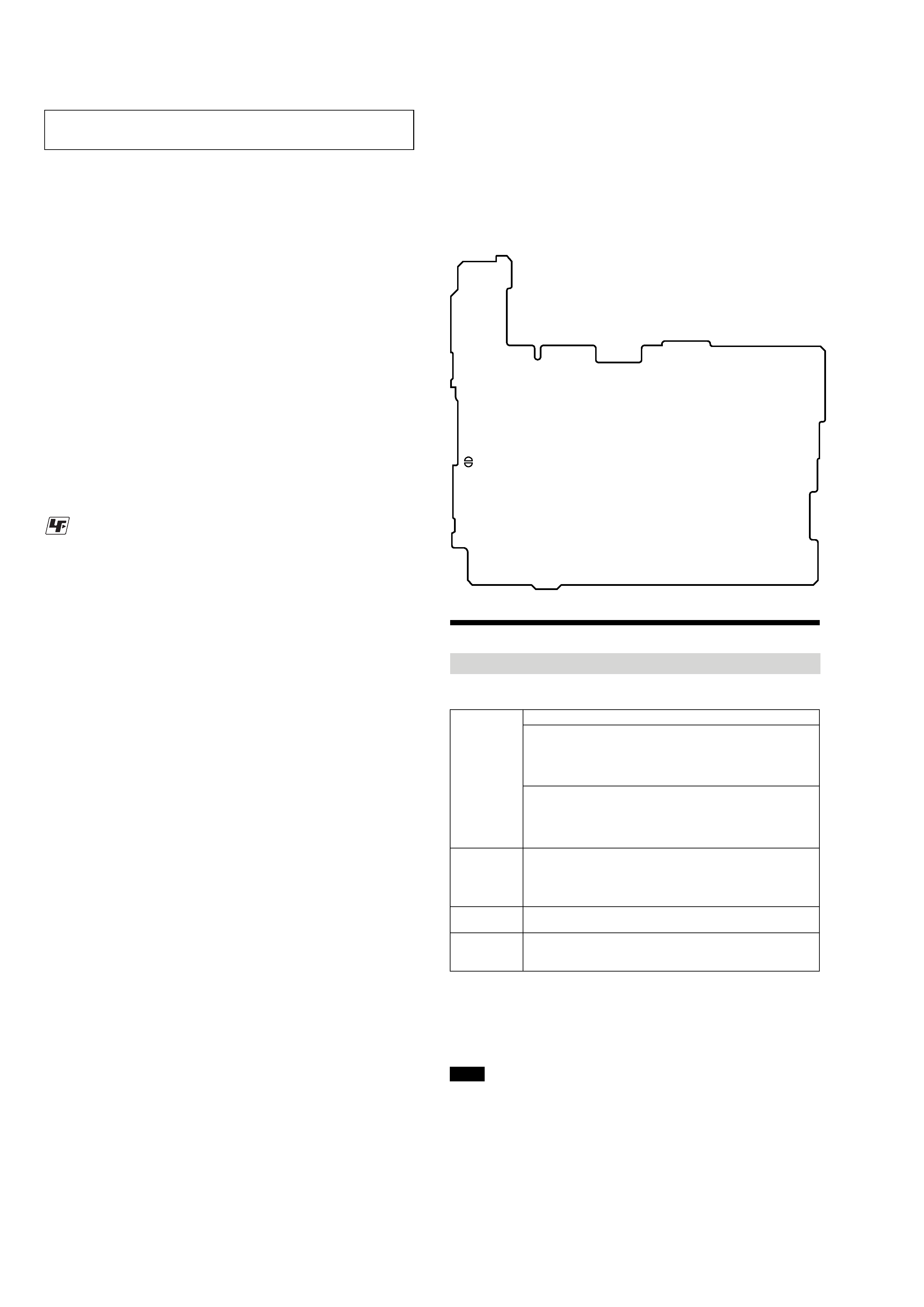
OPERATION CHECK WHEN THE MAIN BOARD IS
REMOVED
In making an operation check with the MAIN board removed from
the set, short the SL894 of the MAIN board with the solder before
starting the operation check.
Note: Be sure to remove the solder used for shortcircuit after the repaire
completed.
SL894
MAIN BOARD (Conductor Side)
UNLEADED SOLDER
Boards requiring use of unleaded solder are printed with the lead-
free mark (LF) indicating the solder contains no lead.
(Caution: Some printed circuit boards may not come printed with
the lead free mark due to their particular size)
: LEAD FREE MARK
Unleaded solder has the following characteristics.
· Unleaded solder melts at a temperature about 40 °C higher
than ordinary solder.
Ordinary soldering irons can be used but the iron tip has to be
applied to the solder joint for a slightly longer time.
Soldering irons using a temperature regulator should be set to
about 350
°C.
Caution: The printed pattern (copper foil) may peel away if
the heated tip is applied for too long, so be careful!
· Strong viscosity
Unleaded solder is more viscou-s (sticky, less prone to flow)
than ordinary solder so use caution not to let solder bridges
occur such as on IC pins, etc.
· Usable with ordinary solder
It is best to use only unleaded solder but unleaded solder may
also be added to ordinary solder.
Providing the required system environment
The following system environment is required in order to use the SonicStage Ver. 3.0/MD
Simple Burner Ver. 2.0 software for the MD Walkman.
This software is not supported by the following environments:
· OSs other than the indicated above
· Personally constructed PCs or operating systems
· An environment that is an upgrade of the original manufacturer-installed operating system
· Multi-boot environment
· Multi-monitor environment
· Macintosh
· We do not ensure trouble-free operation on all computers that satisfy the system requirements.
· The NTFS format of Windows XP/Windows 2000 Professional can be used only with the standard
(factory) settings.
· For Windows 2000 Professional users, install Service Pack 3 or later version before using the
software.
· We do not ensure trouble-free operation of the system suspend, sleep, or hibernation function on all
computers.
System requirements
Computer
IBM PC/AT or Compatible
·CPU: Pentium III 450 MHz or higher
·Hard disk drive space: 200 MB or more (1.5 GB or more is
recommended) (The amount space will vary according to Windows
version and the number of music files stored on the hard disk.)
·RAM: 128 MB or more
Others
·CD drive (capable of digital playback by WDM) (A CD-R/RW drive
is necessary for CD writing)
·Sound Board
·USB port
Operating
System
Factory installed:
Windows XP Media Center Edition 2005/Windows XP Media Center
Edition 2004/Windows XP Media Center Edition/Windows XP
Professional/Windows XP Home Edition/Windows 2000 Professional/
Windows Millennium Edition/Windows 98 Second Edition
Display
High Color (16bit) or higher, 800
600 dots or better (1024
768 dots
or better is recommended)
Others
· Internet access: for Web registration, EMD services and CDDB
·Windows Media Player (version 7.0 or higher) installed for playing
WMA files
Notes
NOTES ON REPLACEMENT OF CSP (CHIP SIZE
PACKAGE) IC
Replacement of SN761059AZQLR (IC501), SC901585VAR2
(IC601) and CXD2681-225GG (IC801) used in this set requires a
special tool.
5
MZ-DH710
SECTION 2
GENERAL
This section is extracted from
instruction manual.
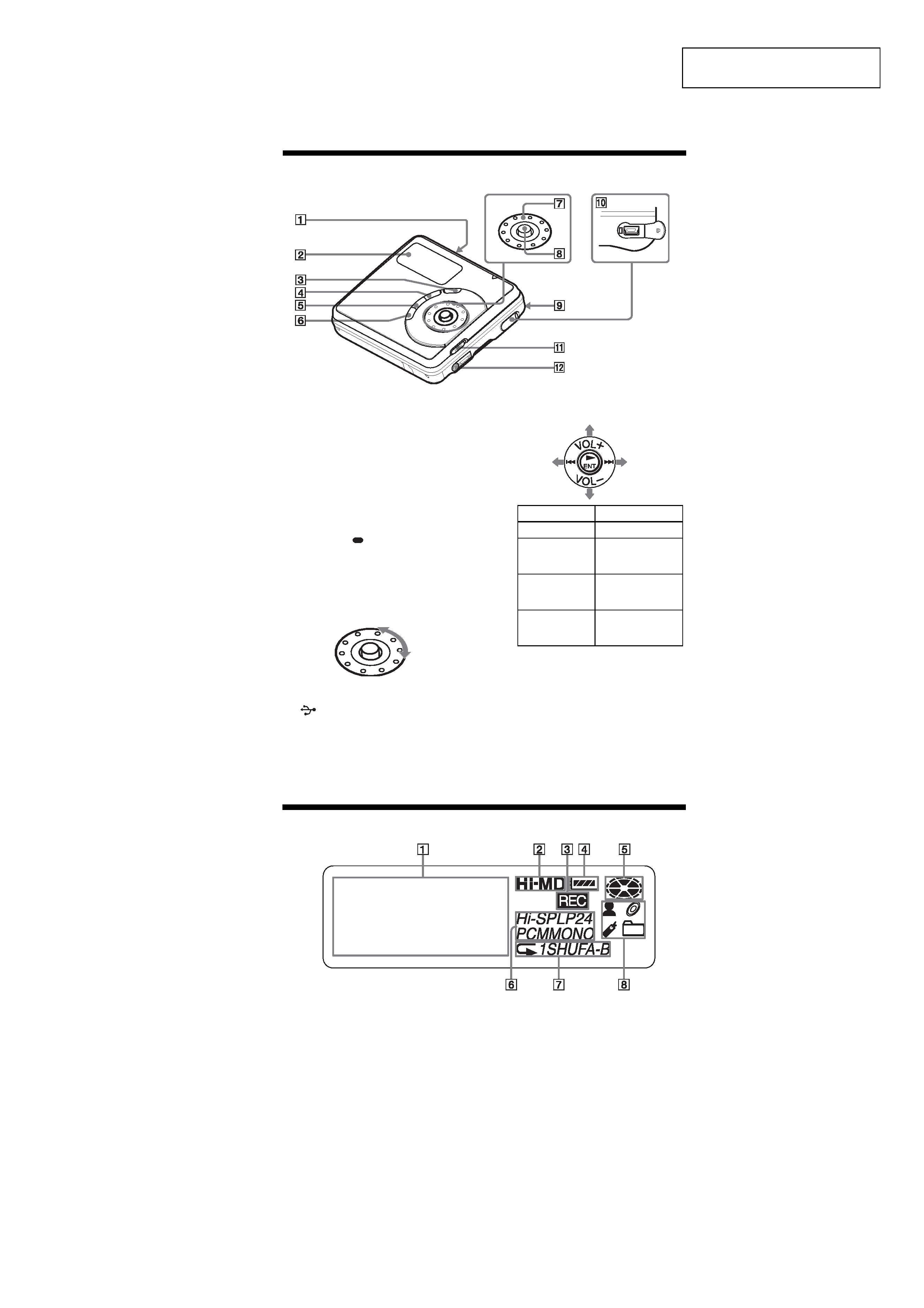
Looking at controls
The player
A OPEN switch
B Display window
C DOWNLOAD button
This button allows you to record
music tracks from an audio CD in the
CD drive of your computer to an MD
Walkman using the supplied MD
Simple Burner software.
D X (pause) button
E ·SEARCH/
MENU button
Press lightly to go to the SEARCH
setting mode. Press for 2 seconds or
more to go to the MENU setting mode.
F x (stop) · CANCEL button
G Jog dial
H 5-way control key
Operation
Function
Press NENT 1)
1) There are tactile dots beside the NENT
and
VOL + buttons.
play, enter
Press towards
.
find the beginning
of the previous
track, rewind
Press towards
>
find the beginning
of the next track,
fast forward
Press towards
VOL +1) or
VOL .
volume
I Battery compartment (at the bottom)
J
USB cable connecting jack
K HOLD switch
Slide the switch in the direction of the
arrow to disable the buttons on the
player. To prevent the buttons from
being accidentally operated when you
carry the player, use this function.
L i (earphones) jack
The display window of the player
A Character information display
Displays the disc and track names,
date, error messages, track numbers,
etc.
B Hi-MD/MD indication
"Hi-MD" lights up when the
operation mode of the player is in Hi-
MD mode and "MD" lights up when
the operation mode is in MD mode.
C REC indication
Lights up during file transfers from
the computer. When flashing, the
player is in record standby mode.
D Battery indication
Shows the approximate remaining
battery power. If the battery is weak,
the indication becomes empty and
starts flashing.
E Disc indication
Shows that the disc is rotating for
playing.
F Track mode (PCM, Hi-SP, Hi-LP, SP,
LP2, LP4, MONO) indication
G Sub play mode/Repeat play
indications
Shows the selected Sub play mode
(single-track play, shuffle play, etc.) or
Repeat play.
H Main play mode indications
Shows the selected main play mode
(group play, bookmark play, etc.).