PORTABLE MINIDISC RECORDER
MZ-B100
SERVICE MANUAL
US Model
Canadian Model
AEP Model
Tourist Model
Ver 1.3 2004.09
With SUPPLEMENT-1
9-873-341-04
2004I02-1
© 2004.09
Sony Corporation
Personal Audio Company
Published by Sony Engineering Corporation
SPECIFICATIONS
Model Name Using Similar Mechanism
NEW
Mechanism Type
MT-MZB100-171
Optical Pick-up Name
LCX-4R
US and foreign patents licensed from Dolby
Laboratories Licensing Corporation
Continued on next page
System
Audio playing system
MiniDisc digital audio system
Laser diode properties
Material: GaAlAs
Wavelength:
= 790 nm
Emission duration: continuous
Laser output: less than 44.6
µW
(This output is the value measured at a distance
of 200 mm from the lens surface on the optical
pick-up block with 7 mm aperture.)
Recording and playback time
When using MDW-80
Maximum 160 min. in monaural.
Maximum 320 min. in stereo
Revolutions
About 350 rpm to 2,800 rpm (CLV)
Error correction
ACIRC (Advanced Cross Interleave Reed
Solomon Code)
Sampling frequency
44.1 kHz
Sampling rate converter
Input: 32 kHz/44.1 kHz/48 kHz
Coding
ATRAC (Adaptive TRansform Acoustic
Coding)
ATRAC3 -- LP2/LP4
Modulation system
EFM (Eight to Fourteen Modulation)
Speaker
28 mm (1 1/8 in.) dia.
Frequency response (digital/analog input)
20 to 20,000 Hz
± 3 dB
Wow and Flutter
Below measurable limit
Inputs
Microphone: stereo mini-jack
(minimum input level 0.25 mV)
Line in 1):
stereo mini-jack for analog input
(minimum input level 39 mV)
optical (digital) mini-jack for optical
(digital) input
Outputs
i
: stereo mini-jack (dedicated remote control
jack)
Maximum output (DC) 2)
Headphones: 5 mW + 5 mW (16 ohm)
Speaker: 70 mW

2
MZ-B100
SAFETY-RELATED COMPONENT WARNING!!
COMPONENTS IDENTIFIED BY MARK 0 OR DOTTED LINE
WITH MARK 0 ON THE SCHEMATIC DIAGRAMS AND IN THE
PARTS LIST ARE CRITICAL TO SAFE OPERATION.
REPLACE THESE COMPONENTS WITH SONY PARTS WHOSE
PART NUMBERS APPEAR AS SHOWN IN THIS MANUAL OR IN
SUPPLEMENTS PUBLISHED BY SONY.
ATTENTION AU COMPOSANT AYANT RAPPORT
À LA SÉCURITÉ!
LES COMPOSANTS IDENTIFÉS PAR UNE MARQUE 0 SUR
LES DIAGRAMMES SCHÉMATIQUES ET LA LISTE DES
PIÈCES SONT CRITIQUES POUR LA SÉCURITÉ DE
FONCTIONNEMENT. NE REMPLACER CES COMPOSANTS
QUE PAR DES PIÈSES SONY DONT LES NUMÉROS SONT
DONNÉS DANS CE MANUEL OU DANS LES SUPPÉMENTS
PUBLIÉS PAR SONY.
Flexible Circuit Board Repairing
· Keep the temperature of the soldering iron around 270
°C during
repairing.
· Do not touch the soldering iron on the same conductor of the
circuit board (within 3 times).
· Be careful not to apply force on the conductor when soldering or
unsoldering.
Notes on chip component replacement
· Never reuse a disconnected chip component.
· Notice that the minus side of a tantalum capacitor may be dam-
aged by heat.
CAUTION
Use of controls or adjustments or performance of procedures
other than those specified herein may result in hazardous
radiation exposure.
1. SERVICING NOTES ....................................................... 3
2. GENERAL .......................................................................... 4
3. DISASSEMBLY
3-1. Panel (Lower) ASSY ..................................................... 6
3-2. Main Board ................................................................... 6
3-3. Cabinet (Belt) Section ................................................... 7
3-4. Key Board Unit ............................................................. 7
3-5. Mechanism Deck .......................................................... 8
3-6. Optical Pick-up Block (LCX-4R) ................................. 9
3-7. Holder ASSY .............................................................. 10
3-8. Motor, DC (Sled) (M602) ........................................... 10
3-9. "Motor, DC (Spindle) (M601)",
"Motor, DC (Over Write Head Up/Down) (M603)" ... 11
4. TEST MODE .................................................................... 12
5. ELECTRICAL ADJUSTMENTS ............................... 19
6. DIAGRAMS
6-1. Explanation of IC Terminals ....................................... 24
6-2. Block Diagrams (Main Section (1/3)) .................. 30
6-3. Block Diagrams (Main Section (2/3)) .................. 31
6-4. Block Diagrams (Main Section (3/3)) .................. 32
6-5. Printed Wiring Board (Main Section (1/2)) .......... 33
6-6. Printed Wiring Board (Main Section (2/2)) .......... 34
6-7. Schematic Diagram (Main Section (1/4)) ............. 35
6-8. Schematic Diagram (Main Section (2/4)) ............. 36
6-9. Schematic Diagram (Main Section (3/4)) ............. 37
6-10. Schematic Diagram (Main Section (4/4)) ............. 38
7. EXPLODED VIEW
7-1. Panel (Lower) Section ................................................. 42
7-2. Panel (Upper Lid) Section .......................................... 43
7-3. Cabinet (Belt) Section ................................................. 44
7-4. Mechanism Deck Section (MT-MZB100-171) ........... 45
8. ELECTRICAL PARTS LIST ....................................... 46
TABLE OF CONTENTS
General
Power requirements
DC 3V
LR6 (size AA) alkaline dry battery (world model only)
Battery operation time
Battery life 1)
When recording2)3)
(Unit: approx.hours) (JEITA4))
Recording mode
Approx. hours
Stereo
9
LP2 Stereo
12.5
LP4 Stereo
15
MONO
12
1) The battery life may be shorter due to operating conditions
and the temperature of the location.
2) When using a Sony LR6 (SG) "STAMINA" alkaline dry
battery (produced in Japan). Recording time may differ
according to the alkaline batteries.
3) When recorded with the built-in microphones.
4) Measured in accordance with the JEITA (Japan Electronics
and Information Technology Industries Association) standard.
When playing1)
(Unit: approx.hours) (JEITA2))
Recording mode
Speaker 3)
Headphones 4)
Stereo
25.5
34.5
LP2 Stereo
27
39.5
LP4 Stereo
30
43
MONO
30
43
1) When using a Sony LR6 (SG) "STAMINA" alkaline dry
battery (produced in Japan).
2) Measured in accordance with the JEITA (Japan Electronics
and Information Technology Industries Association) standard.
3) When played using the built-in speaker.
3) When played using headphones.
Dimensions
Approx. 105.7
× 80.0 × 24.9 mm (w/h/d)
(4 1/4
× 3 1/8 × 1 in.) not incl. projecting parts and controls.
Mass
Approx. 160 g (5.7 oz) (main unit only)
Supplied accessories
Remote control (1)
Headphones (1)
Carrying pouch (1)
Hand strap (1)
Sony LR6 (size AA) alkaline dry battery (1) (JEW)
1) The LINE IN (OPTICAL) jack is used to connect either a digital
(optical) cable or a line (analog) cable.
2) Measured in accordance with JEITA.
Design and specifications are subject to change without notice.
Ver 1.1 2002.03
· Abbreviation
JEW : Tourist
3
MZ-B100
NOTES ON HANDLING THE OPTICAL PICK-UP
BLOCK OR BASE UNIT
The laser diode in the optical pick-up block may suffer electrostatic
break-down because of the potential difference generated by the
charged electrostatic load, etc. on clothing and the human body.
During repair, pay attention to electrostatic break-down and also
use the procedure in the printed matter which is included in the
repair parts.
The flexible board is easily damaged and should be handled with
care.
NOTES ON LASER DIODE EMISSION CHECK
Never look into the laser diode emission from right above when
checking it for adjustment. It is feared that you will lose your sight.
NOTES ON HANDLING THE OPTICAL PICK-UP BLOCK
(LCX-4R)
The laser diode in the optical pick-up block may suffer electrostatic
break-down easily. When handling it, perform soldering
bridge to the laser-tap on the flexible board. Also perform measures
against electrostatic break-down sufficiently before the operation.
The flexible board is easily damaged and should be handled with
care.
OPTICAL PICK-UP FLEXIBLE BOARD
SECTION 1
SERVICING NOTES
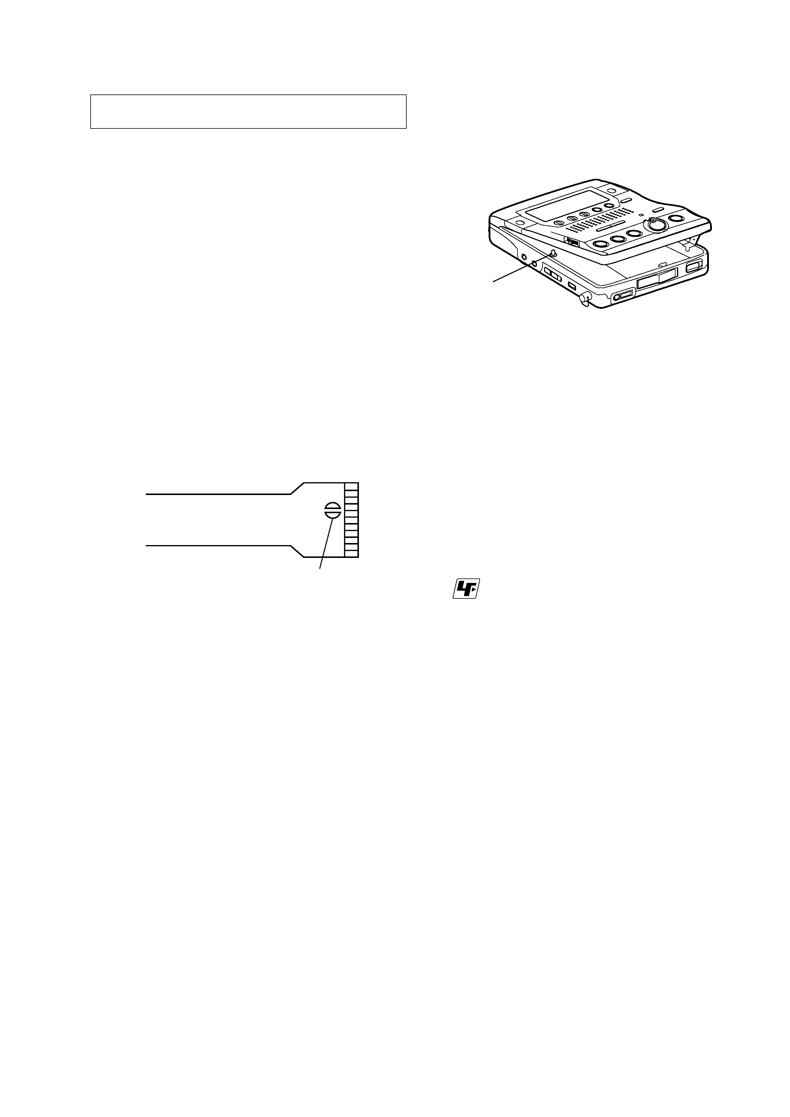
· When repairing this device with the power on, if you remove the
MAIN board or open the upper panel assy, this device stops work-
ing.
In this case, you can work without the device stopping by fasten-
ing the hook of the open/close detect switch (S804).
· This set is designed to perform automatic adjustment for each
adjustment and write its value to EEPROM. Therefore, when
EEPROM (IC802) has been replaced in service, be sure to per-
form automatic adjustment and write resultant values to the new
EEPROM.
(Refer to Section 5 Electrical Adjustment. (page 19))
· Replacement of CXD 2671-209GA (IC801) used in this set re-
quires a special tool.
laser-tap
S804
z
UNLEADED SOLDER
Boards requiring use of unleaded solder are printed with the lead-
free mark (LF) indicating the solder contains no lead.
(Caution: Some printed circuit boards may not come printed with
the lead free mark due to their particular size.)
: LEAD FREE MARK
Unleaded solder has the following characteristics.
· Unleaded solder melts at a temperature about 40
°C higher than
ordinary solder.
Ordinary soldering irons can be used but the iron tip has to be
applied to the solder joint for a slightly longer time.
Soldering irons using a temperature regulator should be set to
about 350
°C.
Caution: The printed pattern (copper foil) may peel away if
the heated tip is applied for too long, so be careful!
· Strong viscosity
Unleaded solder is more viscous (sticky, less prone to flow)
than ordinary solder so use caution not to let solder bridges
occur such as on IC pins, etc.
· Usable with ordinary solder
It is best to use only unleaded solder but unleaded solder may
also be added to ordinary solder.
4
MZ-B100
SECTION 2
GENERAL
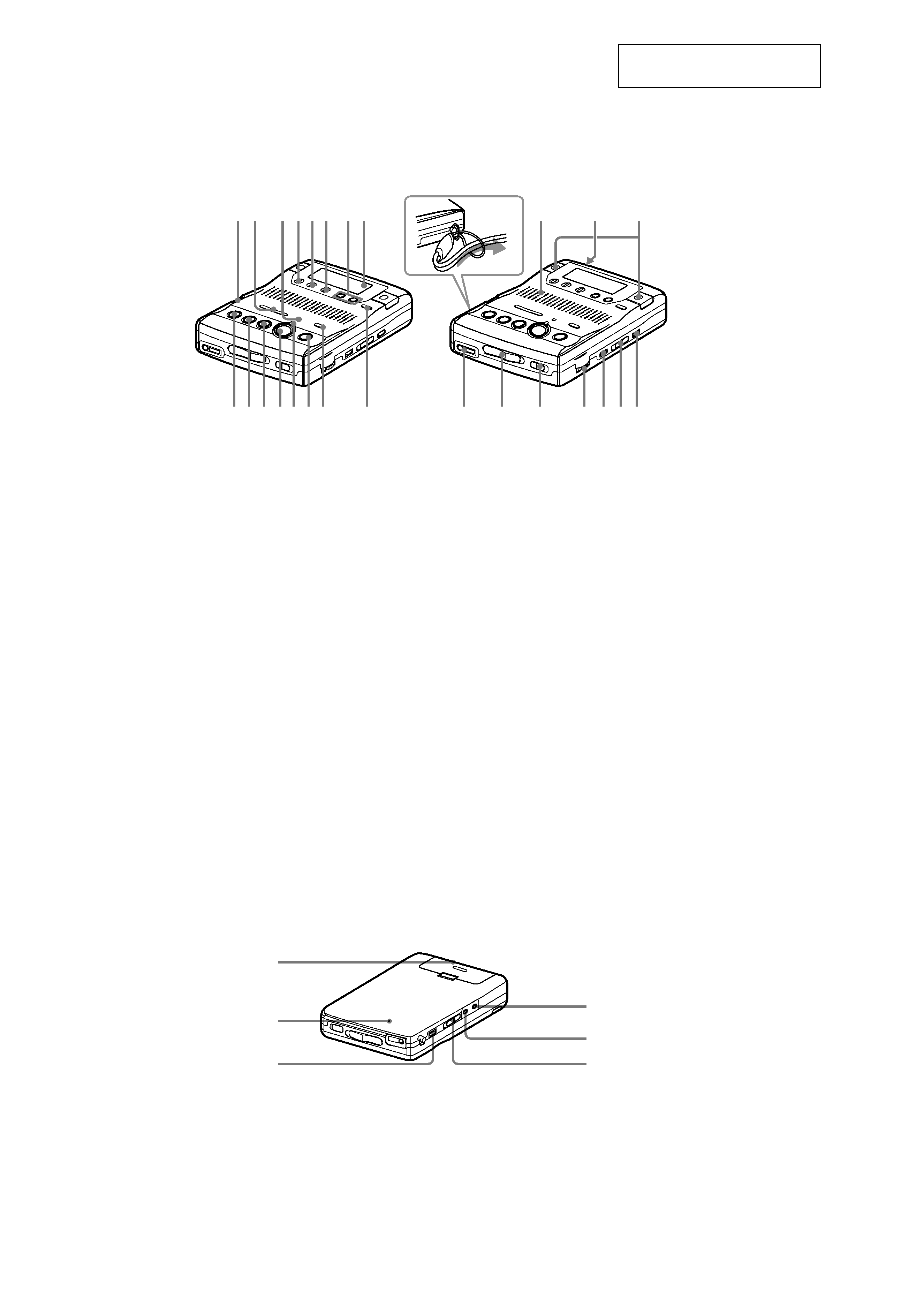
LOCATION AND FUNCTION OF CONTROLS
Front of the recorder
Back of the recorder
This section is extracted from
instruction manual.
1 SPEED CONTROL dial
2 .REVIEW/AMS/>CUE/AMS
(search /AMS) buttons
3 VOR indicator
4 DISPLAY button
5 PLAY MODE button
6 EDIT/ENTER button
7 EASY SEARCH +/ buttons
8 Display window
9 x STOP button
0 N PLAY (play) button
The N PLAY button has a tactile dot.
qa X PAUSE button
qs z REC button
qd REC indicator
1 Battery compartment
2 CLOCK SET button
3 SOUND button
4 LINE IN (OPTICAL) jack
1 2
9q;qa qsqdqfqg
qh
w;
wa
ws
wd wf wgwh
3456 78
qj
qk
ql
How to attach the hand strap.
2
1
3
4
5
6
qf TRACK MARK button
qg REC MODE switch
qh GROUP button
qj Speaker
qk DC IN 3V jack
ql Microphones
w; i (headphones) jack
wa OPEN switch
ws HOLD switch
wd VOL control
The VOL control has a tactile dot.
wf VOR button
wg SYNCHRO REC ON/OFF switch
wh ERASE button
5 MIC (PLUG IN POWER) jack
The MIC (PLUG IN POWER) jack
has a tactile dot.
6 MIC SENS (H/L) switch
5
MZ-B100
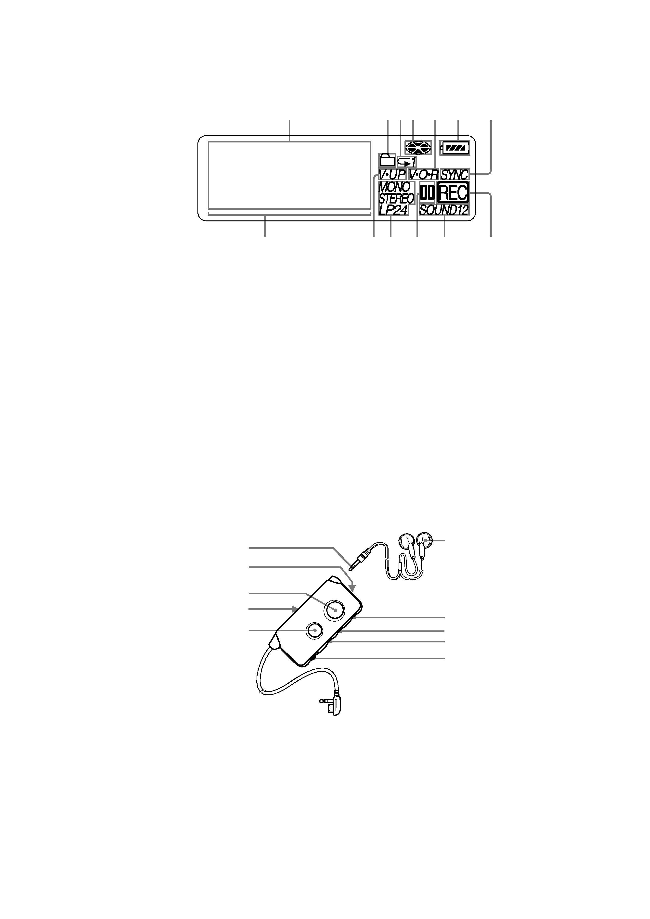
1 Character information display
Displays the disc and track names,
date, error messages, track numbers,
recording level, etc.
2 Group indication
3 Play mode indication
4 Disc indication
Shows that the disc is rotating for
recording, playing or editing an MD.
5 VOR indication
1 Stereo mini plug
2 SOUND button
3 TRACK MARK button
4 HOLD switch
Slide to lock the controls of the remote
control.
5 X (pause) button
The display window
The remote control
1
2
45
6
7
qd
qs
qa
q;
9
8
3
A
B
C
D
E
G
F
H
I
J
6 Battery level indication
7 SYNC (synchro-recording) indication
8 Playback level meter
9 V-UP indication
0 STEREO (stereo), LP2 (LP2 stereo),
LP4 (LP4 stereo), MONO (monaural)
indication
qa Pause indication
qs SOUND indication
qd REC indication
6 Headphones
7 x (stop) button
8 >N buttons
The >N buttons has a tactile dot.
9 .REVIEW/AMS
0 VOL control
The VOL control has a tactile dot.