SERVICE MANUAL
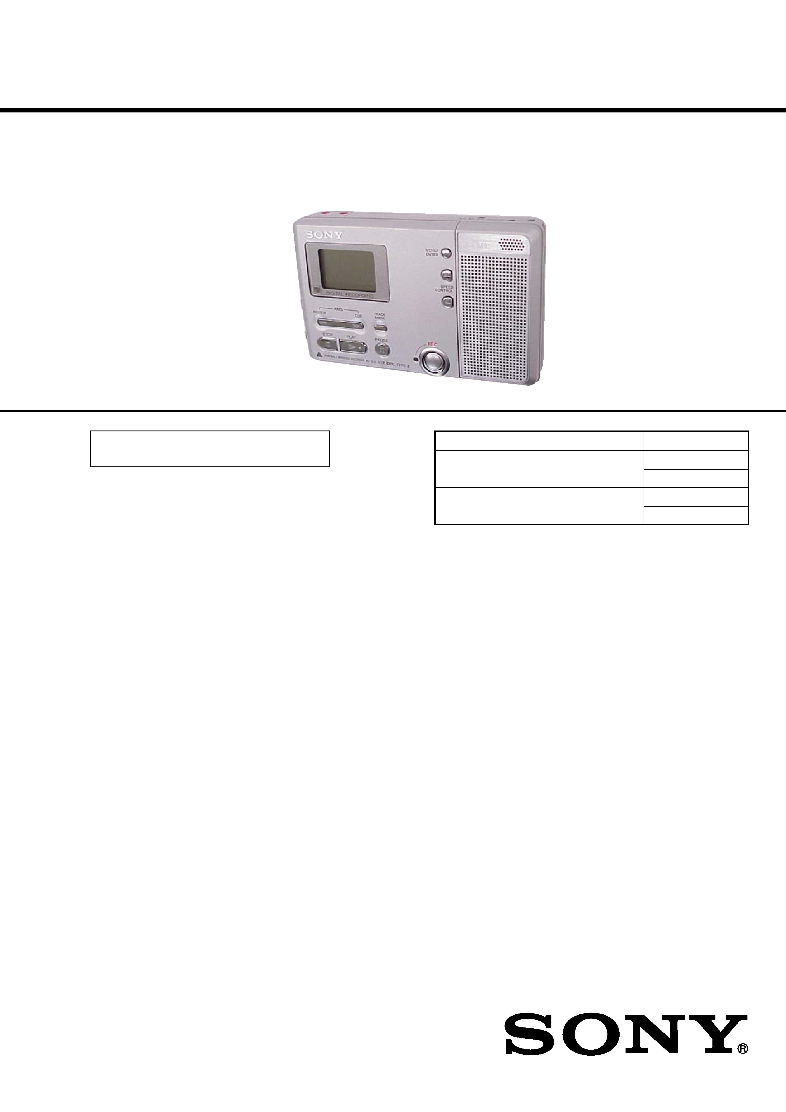
PORTABLE MINIDISC RECORDER
US Model
AEP Model
Tourist Model
SPECIFICATIONS
MZ-B10
US and foreign patents licensed from Dolby
Laboratories.
Continued on next page
Model Name Using Similar Mechanism
NEW
Mechanism Type
MT-MZN710-177
MT-MZN710-177G
Optical Pick-up Name
LCX-5R
LCX-5RG
Ver. 1.3 2005.09
9-877-031-04
Sony Corporation
2005I16-1
Personal Communications Business Division
C
2005.09
Published by Sony Engineering Corporation
Audio playing system
MiniDisc digital audio system
Laser diode properties
Material: GaAlAs
Wavelength:
= 790 nm
Emission duration: continuous
Laser output: less than 44.6
µW
(This output is the value measured at a distance
of 200 mm from the lens surface on the optical
pick-up block with 7 mm aperture.)
Recording and playback time
When using MDW-80
Maximum 160 min. in monaural.
Maximum 320 min. in LP4 stereo
Revolutions
350 rpm to 2,800 rpm (CLV)
Error correction
ACIRC (Advanced Cross Interleave Reed
Solomon Code)
Sampling frequency
44.1 kHz
Sampling rate converter
Input: 32 kHz/44.1 kHz/48 kHz
Coding
ATRAC (Adaptive TRansform Acoustic
Coding)
ATRAC3 -- LP2/LP4
Modulation system
EFM (Eight to Fourteen Modulation)
Speakers (two units)
28 mm (11/8 in.) dia. per unit
Frequency response (digital/analog
input)
20 to 20,000 Hz
± 3 dB
Inputs
Microphone: stereo mini-jack
(minimum input level 0.25 mV)
Line in1):
stereo mini-jack for analog input
(minimum input level 39 mV)
optical (digital) mini-jack for optical
(digital) input
Outputs
i: stereo mini-jack (dedicated remote control
jack)
Maximum output (DC)2)
Headphones/earphones: 5 mW + 5 mW (16
)
Speakers (monaural): 140 mW (70 mW
× 2)
General
Power requirements
AC power adaptor DC 3V
LR6 (size AA) alkaline dry battery
Dimensions2)
Approx. 117.2
× 23.0 × 74.4 mm (w/h/d)
(45/8
× 29/32 × 3 in.) not incl. projecting parts
and controls.
Mass
Approx. 150 g (5.3 oz) (main unit only)
1) The LINE IN (OPTICAL) jack is used to
connect either a digital (optical) cable or a line
(analog) cable.
2) Measured in accordance with JEITA.
Supplied accessories
Design and specifications are subject to change
without notice.
Headphones/earphones (1)
Carrying pouch (1)
Handstrap (1)
Clamp filter for the AC power adaptor (1)
Attach the clamp filter when using the optional
AC power adaptor.
Headphones/earphones (1)
LR6 (size AA) alkaline dry
batteries (2) (World model only)
2
MZ-B10
CAUTION
Use of controls or adjustments or performance of procedures
other than those specified herein may result in hazardous ra-
diation exposure.
Notes on chip component replacement
·Never reuse a disconnected chip component.
· Notice that the minus side of a tantalum capacitor may be dam-
aged by heat.
Flexible Circuit Board Repairing
·Keep the temperature of the soldering iron around 270 °C dur-
ing repairing.
· Do not touch the soldering iron on the same conductor of the
circuit board (within 3 times).
· Be careful not to apply force on the conductor when soldering
or unsoldering.
UNLEADED SOLDER
Boards requiring use of unleaded solder are printed with the lead-
free mark (LF) indicating the solder contains no lead.
(Caution: Some printed circuit boards may not come printed with
the lead free mark due to their particular size)
: LEAD FREE MARK
Unleaded solder has the following characteristics.
· Unleaded solder melts at a temperature about 40 °C higher than
ordinary solder.
Ordinary soldering irons can be used but the iron tip has to be
applied to the solder joint for a slightly longer time.
Soldering irons using a temperature regulator should be set to
about 350 °C .
Caution: The printed pattern (copper foil) may peel away if the
heated tip is applied for too long, so be careful!
· Strong viscosity
Unleaded solder is more viscous (sticky, less prone to flow) than
ordinary solder so use caution not to let solder bridges occur
such as on IC pins, etc.
· Usable with ordinary solder
It is best to use only unleaded solder but unleaded solder may
also be added to ordinary solder.
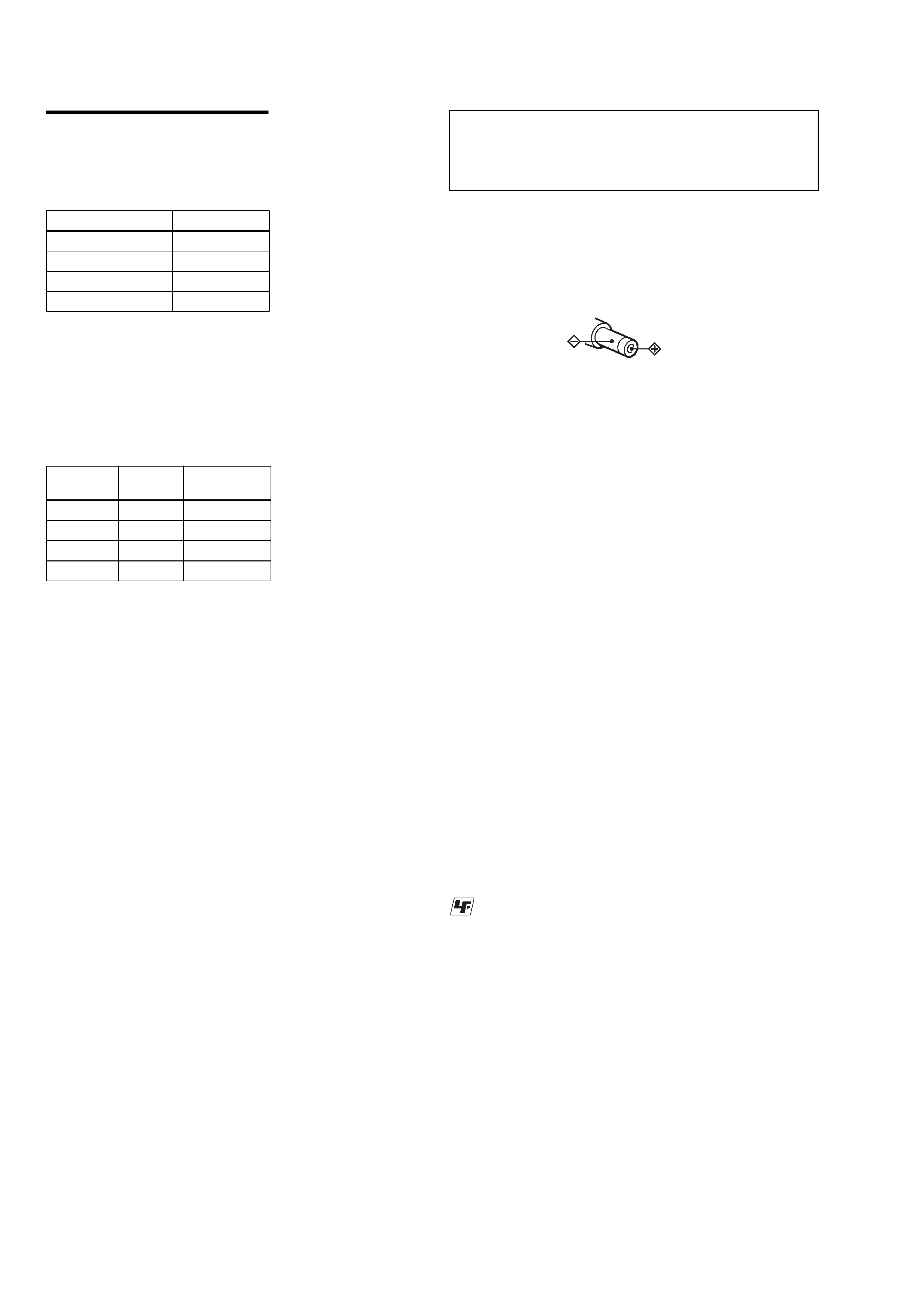
On power sources
· Use house current, LR6 (size AA) battery.
· For use in your house: use the AC power adaptor
supplied with this recorder. Do not use any other
AC power adaptor since it may cause the recorder
to malfunction.
· Connect the AC power adaptor to an easily
accessible AC outlet. Should you notice an
abnormality in the AC power adaptor,
disconnect it from the AC outlet immediately.
· The recorder is not disconnected from the AC
power source (mains) as long as it is
connected to the wall outlet, even if the
recorder itself has been turned off.
· If you are not going to use this recorder for a
long time, be sure to disconnect the power
supply (AC power adaptor, dry battery). To
remove the AC power adaptor from the wall
outlet, grasp the adaptor plug itself; never pull
the cord.
Polarity of the
plug
SAFETY-RELATED COMPONENT WARNING!!
COMPONENTS IDENTIFIED BY MARK 0 OR DOTTED
LINE WITH MARK 0 ON THE SCHEMATIC DIAGRAMS
AND IN THE PARTS LIST ARE CRITICAL TO SAFE
OPERATION. REPLACE THESE COMPONENTS WITH
SONY PARTS WHOSE PART NUMBERS APPEAR AS
SHOWN IN THIS MANUAL OR IN SUPPLEMENTS PUB-
LISHED BY SONY.
Battery life
The battery life may be shorter due to operating
conditions and the temperature of the location.
When recording1)2)
(Unit: approx.hours)(JEITA3))
1) When using a Sony LR6 (SG) "STAMINA"
alkaline dry batteries (produced in Japan) and
"PowerMode" is set to "NORMAL"
(page 40). Setting "PowerMode" to "QUICK"
result in a shorter battery life (page 40).
2) When recorded with the built-in microphone.
Recording mode
Approx. hours
SP
24
LP2
34
LP4
48
MONO
34
Notes
Stop the recorder before replacing batteries.
An optional AC power adaptor is
recommended for long recording.
3) Measured in accordance with the JEITA
(Japan Electronics and Information
Technology Industries Association) standard.
When playing1)
(Unit: approx.hours)(JEITA2))
Recording
mode
Speaker3) Headphones/
earphones4)
SP
45
90
LP2
50
100
LP4
55
110
MONO
50
100
1) When using a Sony LR6 (SG) "STAMINA"
alkaline dry batteries (produced in Japan) and
"PowerMode" is set to "NORMAL" (page 40).
2) Measured in accordance with the JEITA
(Japan Electronics and Information
Technology Industries Association) standard.
3) When played using the built-in speaker.
4) When played using headphones/earphones.

3
MZ-B10
TABLE OF CONTENTS
1. SERVICING NOTES ...................................................... 4
2. GENERAL .......................................................................... 5
3. DISASSEMBLY
3-1.
Disassembly Flow ........................................................ 6
3-2.
Case (Lower) Assy ....................................................... 7
3-3.
Speaker Assy ................................................................ 7
3-4.
MAIN Board ................................................................ 8
3-5.
Electret Condenser Microphone (MIC901) ................ 8
3-6.
Set Chassis Assy, Case (Spk) Assy ............................ 9
3-7.
Case (Upper) Assy ....................................................... 9
3-8.
LCD Module .............................................................. 10
3-9.
Rec Button Assy ........................................................ 10
3-10. Mechanism Deck (MT-MZN710-177) ...................... 11
3-11. Gear (SA), OP Service Assy (LCX-5R) ................... 12
3-12. Holder Assy ............................................................... 13
3-13. DC Motor (Sled) (M602) .......................................... 13
3-14. DC Motor (Over Write Head Up/Down) (M603),
DC SSM18B Motor (Spindle) (M601) ..................... 14
4. TEST MODE .................................................................. 15
5. ELECTRICAL ADJUSTMENTS ............................. 20
6. DIAGRAMS
6-1.
Block Diagram ......................................................... 35
6-2.
Note For Printed Wiring Board
And Schematic Diagrams .......................................... 36
6-3.
Printed Wiring Board MAIN Board (Side A) .... 37
6-4.
Printed Wiring Board MAIN Board (Side B) .... 38
6-5.
Schematic Diagram MAIN Board (1/4) ............. 39
6-6.
Schematic Diagram MAIN Board (2/4) ............. 40
6-7.
Schematic Diagram MAIN Board (3/4) ............. 41
6-8.
Schematic Diagram MAIN Board (4/4) ............. 42
6-9.
IC Pin Function Description ...................................... 47
7. EXPLODED VIEWS
7-1.
Lower Case Section ................................................... 53
7-2.
Upper Chassis Section ............................................... 54
7-3.
Chassis Section .......................................................... 55
7-4.
Mechanism Deck Section-1 (MT-MZN710-177) ....... 56
7-5.
Mechanism Deck Section-2 (MT-MZN710-177) ....... 57
8. ELECTRICAL PARTS LIST ....................................... 58
4
MZ-B10
NOTES ON HANDLING THE OPTICAL PICK-UP
BLOCK OR BASE UNIT
The laser diode in the optical pick-up block may suffer electro-
static break-down because of the potential difference generated
by the charged electrostatic load, etc. on clothing and the human
body.
During repair, pay attention to electrostatic break-down and also
use the procedure in the printed matter which is included in the
repair parts.
The flexible board is easily damaged and should be handled with
care.
NOTES ON LASER DIODE EMISSION CHECK
Never look into the laser diode emission from right above when
checking it for adjustment. It is feared that you will lose your sight.
NOTES ON HANDLING THE OPTICAL PICK-UP BLOCK
(LCX-5R)
The laser diode in the optical pick-up block may suffer electro-
static break-down easily. When handling it, perform soldering
bridge to the laser-tap on the flexible board. Also perform mea-
sures against electrostatic break-down sufficiently before the op-
eration. The flexible board is easily damaged and should be handled
with care.
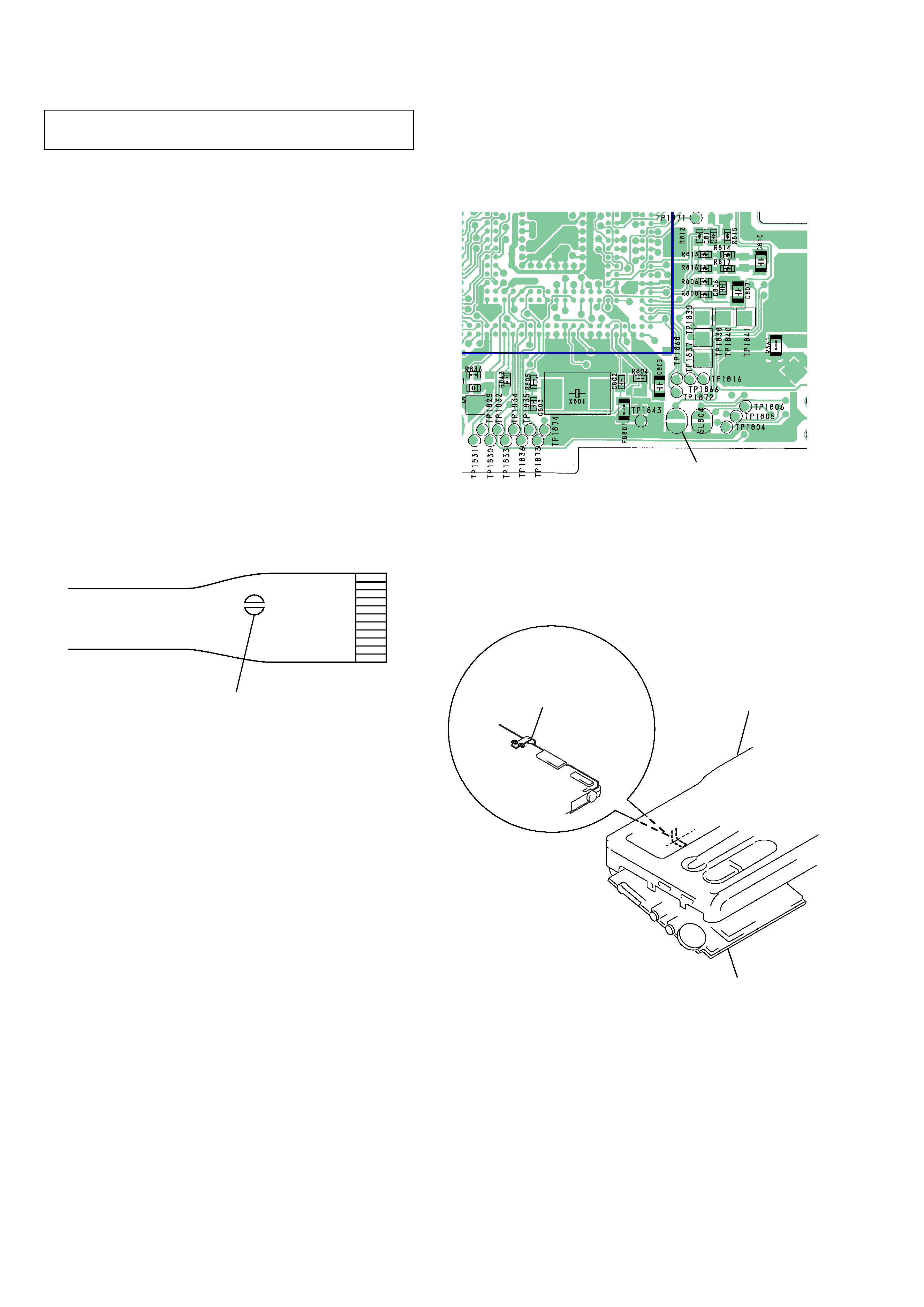
OPTICAL PICK-UP FLEXIBLE BOARD
SECTION 1
SERVICING NOTES
laser-tap
· In performing the repair with the power supplied to the set, re-
moving the MAIN board causes the set to be disabled.
In such a case, make a solder bridge to short SL802 (OPEN
CLOSE) on the MAIN board in advance.
·This set requires the patch data in the nonvolatile memory
(IC802) to be rewritten, when the nonvolatile memory was re-
placed. (See page 30)
case (upper) assy
MAIN board
flexible board
(over write head)
· Handle the FLEXIBLE board (over write head) with care, as it
has been soldered directly to the MAIN board.
In repairing the component side of MAIN board, connect the
FLEXIBLE board (over write head) and the MAIN board with
the lead wires in advance.
IC801
*
CSP(Chip Size Package)
SL802
(OPEN/CLOSE)
SL802
(OPEN/CLOSE)
MAIN Board (Side B)
5
MZ-B10
SECTION 2
GENERAL
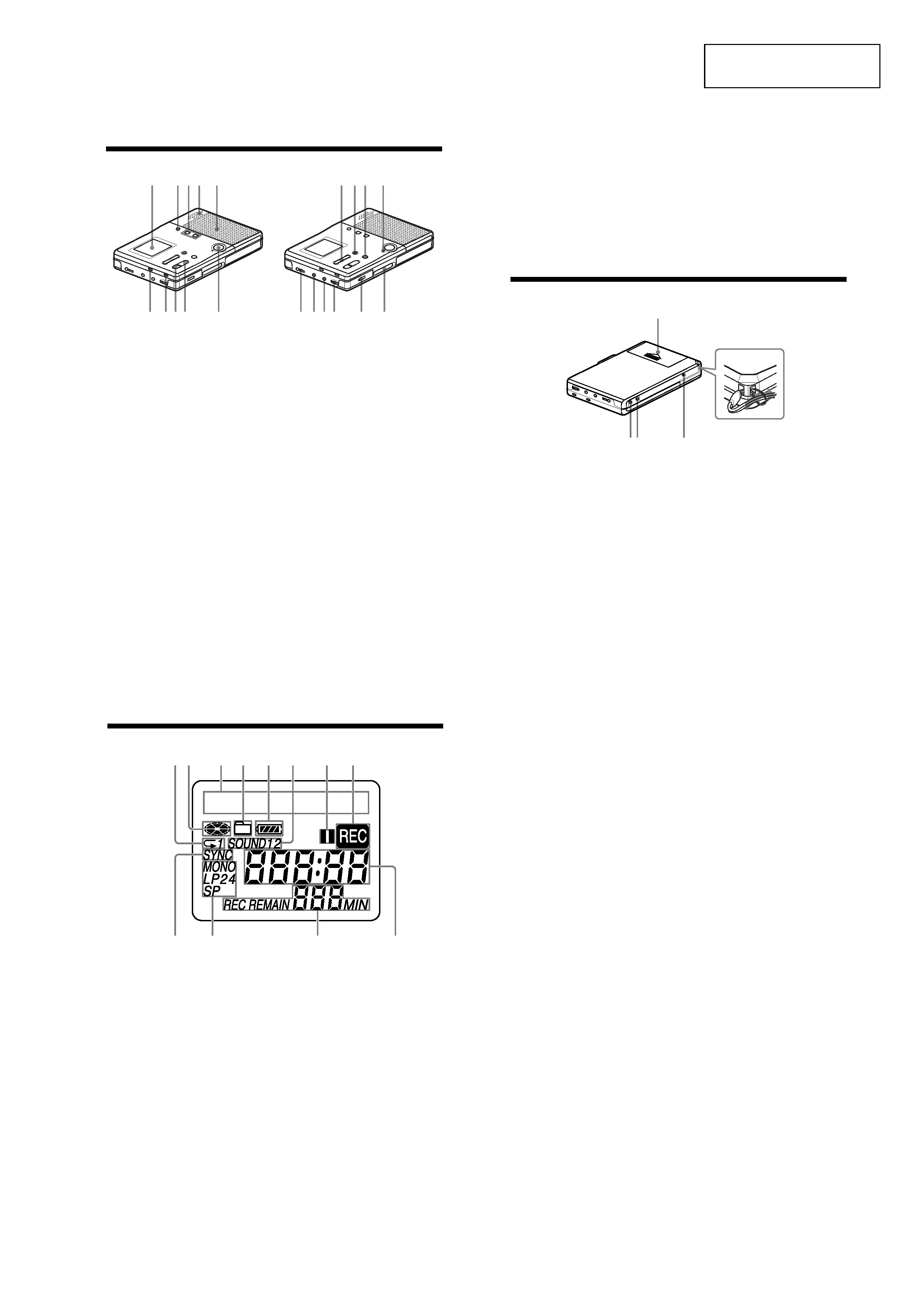
Looking at the controls
Front of the recorder
A Display window
B MENU/ENTER button
You can use various settings using
menu items.
C SPEED CONTROL +, button
Use this button to increase or decrease
the playback speed.
D Built-in microphone
E Speakers
F REC MODE button
Use this button to select 2 times
normal (LP2 or monaural) or 4 times
(LP4) the normal (SP) recording time.
G GROUP button
This button is used when cueing to a
group or erasing a group.
H x STOP button
I N PLAY (play) button
The N
· PLAY button has a tactile
dot.
J REC button
K .
· REVIEW · AMS, > CUE
AMS (search /AMS) buttons
L TRACK MARK button
Use this button to add track marks
automatically or to divide a track into
separate tracks.
M X PAUSE button
N REC indicator
Lights up while recording.
O i (headphones/earphones) jack
Connect headphones or earphones to
this jack.
1
6789
q;
24
35
qg qhqjqk
ql
w;
qa qsqd
qf
·
·
·
·
9
10
P MIC (PLUG IN POWER) jack
Connect an optional stereo
microphone to this jack to record.
The MIC (PLUG IN POWER) jack
has a tactile dot.
Q LINE IN (OPTICAL) jack
Connect an optional optical or line
cable to this jack to record from a CD,
etc.
R VOL control
The VOL control has a tactile dot.
S HOLD switch
Slide the switch in the direction of the
arrow (a yellow mark appears) to
disable the buttons on the recorder. To
prevent the buttons from being
accidentally operated when you carry
the recorder, use this function.
T OPEN switch
Back of the recorder
A Battery compartment
Insert two alkaline dry batteries (size
AA) here.
B ERASE button
During playback, press this button to
erase the track.
C ALL ERASE button
Press ERASE while pressing this
button to erase the contents of an
entire disc.
D DC IN 3V jack
When you connect an optional AC
power adaptor, connect it to this jack.
E Handstrap hole
2
1
34
5
How to attach a hand strap
The display window
A Play mode indication
Lights up when selecting specific play
mode.
B Disc indication
Shows that the disc is rotating for
recording, playing or editing an MD.
C Character information display
Displays the disc and track names,
error messages, track numbers, etc.
D Group indication
Lights up while in group play. Flashes
while selecting a group.
E Battery level indication
F SOUND indication
Lights up when the sound mode
(SOUND 1, SOUND 2) is selected.
G Pause indication
H REC indication
I SYNC (synchro-recording) indication
J SP, LP2, LP4, MONO indication
Shows the recording mode while
recording and SP/LP mode of a track
while playing.
K REC REMAIN indication
Shows the remaining recordable time
in a disc while recording or stopped.
L Time indication
Shows the elapsed time while
recording or playing.
12
3
4
9q;
qa
qs
56
7
8
11
This section is extracted
from instruction manual.