SERVICE MANUAL
COMPACT DISC MINIDISC DECK
US Model
SPECIFICATIONS
MXD-D400
US and foreign patents licensed from Dolby
Laboratories.
CD player section
System
Compact Disc digital
audio system
Laser
Semiconductor laser
(
=780 nm)
Frequency response
20 Hz 20 kHz (
±0.5 dB)
Wow and flutter
Below measureable limit
(
±0.001% W.PEAK)
MD deck section
System
MiniDisc digital audio system
Disc
MiniDisc
Laser
Semiconductor laser
(
=780 nm)
Emission duration:
continuous
Sampling frequency
44.1 kHz
Frequency response
20 Hz 20 kHz (
±0.5 dB)
Inputs
Jack type
Input
impedance
Rated
input
Minimum
input
ANALOG IN Pin jack
47 kilohms
500 mVrms
250 mVrms
DIGITAL
OPTICAL IN
Squqre
optical
connector
jack
Optical wave
length:
660 nm
Outputs
General
Power requirements
120 V AC, 60 Hz
Power consumption
19 watts
Less than 1 watt (at the
power saving mode)
Dimensions (w/h/d) incl. projecting parts and controls
Approx. 430
× 108 × 399 mm
Mass
Approx. 5.4 kg
Supplied accessories
Design and specifications are subject to change
without notice.
Jack type
Rated output
Load
impedance
ANALOG OUT
Pin jack
2 Vrms
(at 47 kilohms)
Over 10 kilohms
DIGITAL
OPTICAL OUT
Squqre optical
connector jack
-18 dBm
Optical wave
length:660 nm
PHONES
Stereo phone
jack
10 mW
32 ohm
· Audio connection cords (2)
· Remote commander (remote) (1)
· Sony R6 (size-AA) batteries (2)
Ver. 1.1 2005.03
9-877-241-02
Sony Corporation
2005C05-1
Audio Group
© 2005.03
Published by Sony Engineering Corporation
Model Name Using Similar Mechanism
NEW
MD Mechanism Type
MDM-7S2C
Optical Pick-up Name
KMS-262E
Model Name Using Similar Mechanism
NEW
CD Mechanism Type
CDM66C-30B61M
Base Unit Name
BU-30BD61B
Optical Pick-up Name
OP Assy (A-MAX.4T)
MD
Section
CD
Section
2
MXD-D400
SELF-DIAGNOSIS FUNCTION
The self-diagnosis function consists of error codes for customers which are displayed automatically when errors occur, and error codes
which show the error history in the test mode during servicing. For details on how to view error codes for the customer, refer to the
following box in the instruction manual. For details on how to check error codes during servicing, refer to the following "Procedure for
using the Self-Diagnosis Function (Error History Display Mode)".
PROCEDURE FOR USING THE SELF-DIAGNOSIS FUNCTION (ERROR HISTORY DISPLAY MODE)
Note: Perform the self-diagnosis function in the "error history display mode" in the test mode. The following describes the least required procedure. Be
careful not to enter other modes by mistake. If you set other modes accidentally, pull out the AC cord to turn the power off and retry to enter the test
mode.
1. Press the ?/1 button to turn he power on.
2. Press the [
AMS
] (CD) knob and [INPUT] button at the same time, press the [
AMS
] (MD) knob to display "SYS
version".
3. Turn the [
AMS
] (CD) knob and when "MD Test" is displayed, press the [
AMS
] (MD) knob.
4. Turn the [
AMS
] (MD) knob and when "[Service]" is displayed, press the [YES] button.
5. Turn the [
AMS
] (MD) knob to display "Err Display".
6. Press the [YES] button to sets the error history mode and displays "op rec tm".
7. Select the contents to be displayed or executed using the [
AMS
] (MD) knob.
8. Press the [
AMS
] (MD) knob to display or execute the contents selected.
9. Press the [
AMS
] (MD) knob another time returns to step 6.
10. Press the [MENU/NO] button to display "Err Display" and release the error history mode.
11. To release the test mode, press the [
AMS
] (CD) knob and [INPUT] button at the same time, press the [
AMS
] (MD)
knob.
12. Press the ?/1 button to turn the power off.
lL
lL
lL
lL
lL
lL
lL
lL
l
L
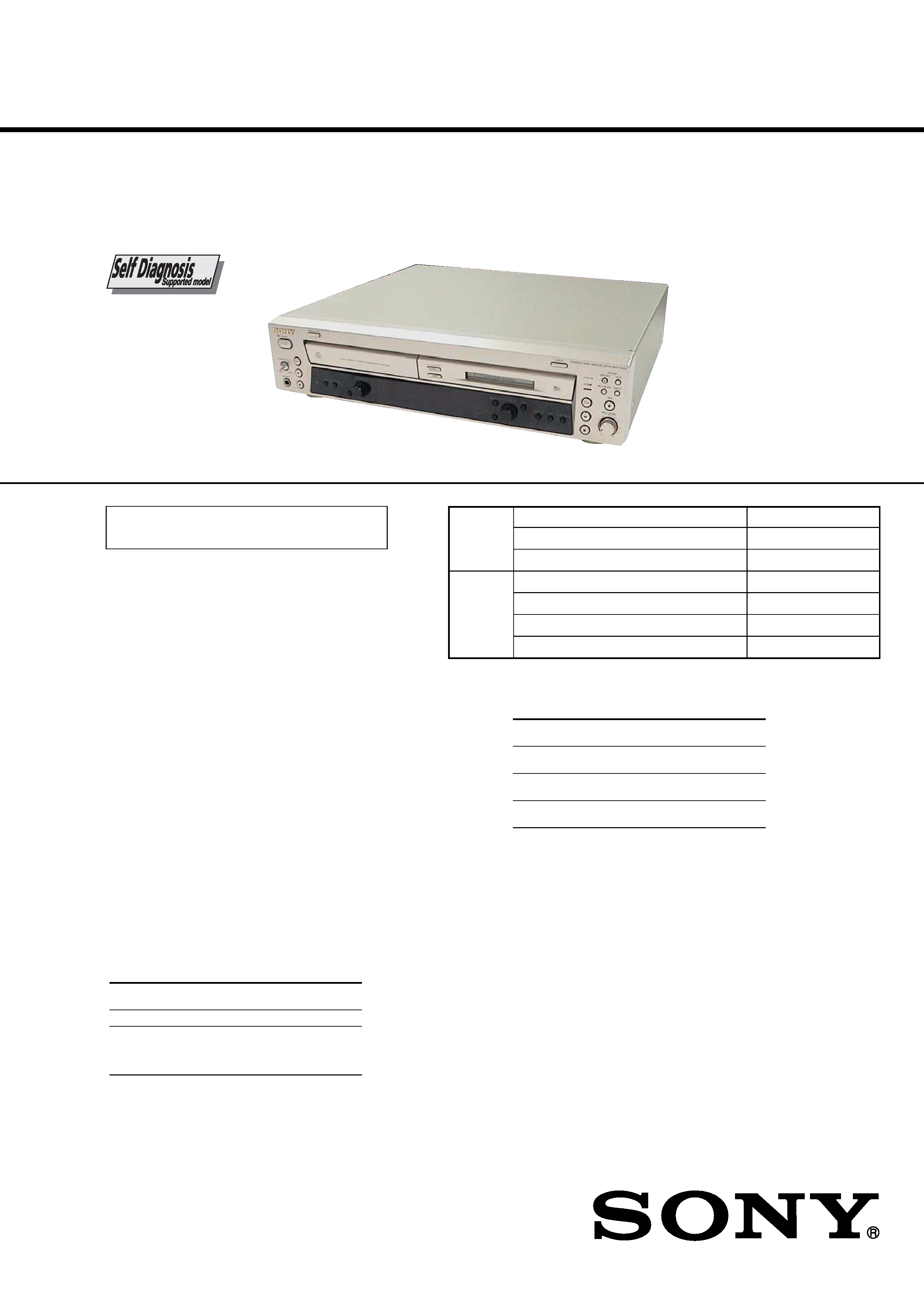
This deck has a Self-diagnosis display function
to let you know if there is a deck malfunction.
The display shows a code made up of three or
five letters and a message alternately to show
you the problem. To solve the problem refer to
the following list. If any problem persists,
consult your nearest Sony dealer.
C11/Protected
The MD is protected against erasure.
cRemove the MD and slide the tab to close the slot.
C12/Cannot Copy
You tried to record a CD with a format that the deck
does not support, such as a CD-ROM or MD data.
cReplace the playable disc.
C13/REC Error
Recording could not be performed properly.
cMove the deck to a stable place, and start
recording over from the beginning.
The MD is dirty or scratched, or the MD does not
meet the standards.
cReplace the MD and start recording over from the
beginning.
C13/Read Error
The MD deck cannot read the disc information
properly.
cRemove the MD once, then insert it again.
C41/Cannot Copy
The digitally dubbed material cannot be recorded
digitally.
C71/Din Unlock
The digitally dubbed material cannot be recorded
digitally.
A moment's lighting is due to the signals of the
digital program being recorded. This does not affect
the recorded material.
The digital optical cable is disconnected, or the
power of the connected component is turned off
while recording the digital audio from the
component connected to the DIGITAL OPTICAL
IN jack.
cConnect the digital optical cable, or turn on the
power of the connected component.
E0001/MEMORY NG
The component has internal problem.
cConsult your nearest Sony dealer.
E0101/LASER NG
There is a problem with the laser pickup.
cThe laser pickup may be damaged. Consult your
nearest Sony dealer.
E0201/LOADING NG
There is a problem with the loading.
cThe loading may be failed. Consult your nearest
Sony dealer.
C14/TOC Error
The MD deck cannot read the disc information
properly.
cReplace the MD.
cErase all the recorded contents of the MD using
the All Erase Function.
lL
lL
3
MXD-D400
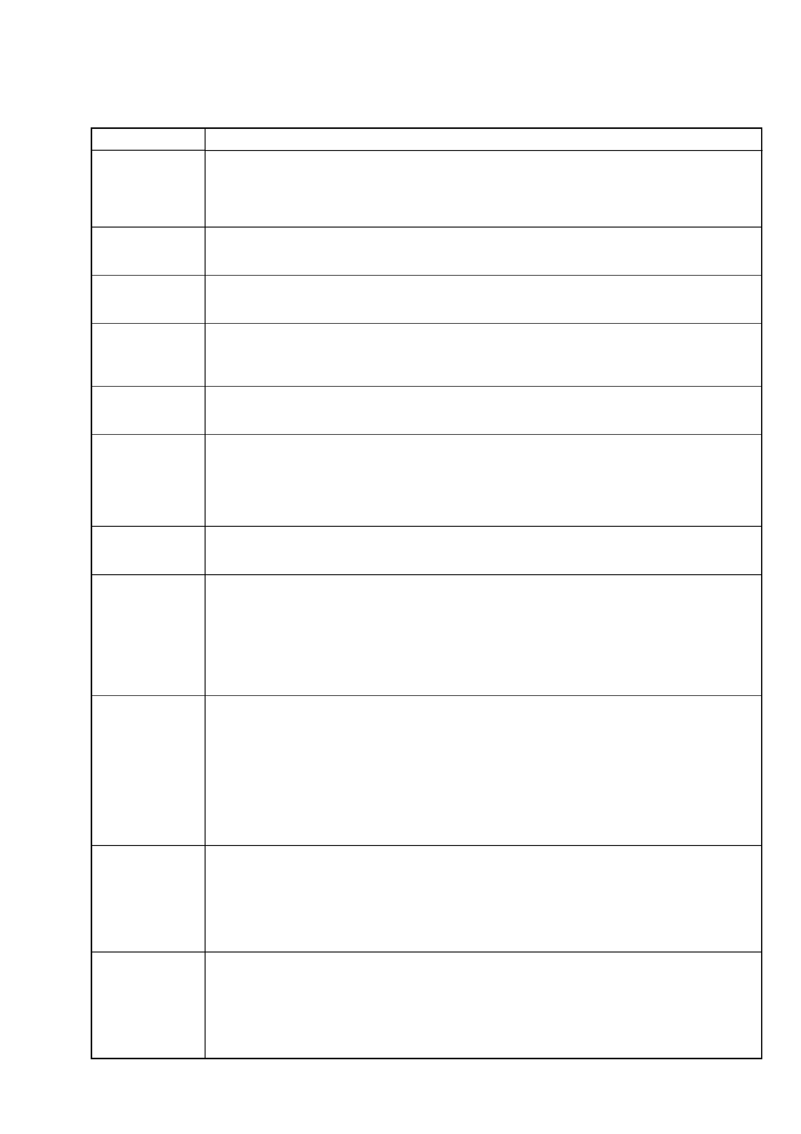
ITEMS OF ERROR HISTORY MODE ITEMS AND CONTENTS
Selecting the Test Mode
Display
Details of History
op rec tm
Cumulative recording time is displayed.
When cumulative recording time is over 1 minute, the hour and minute are displayed as they are.
When it is under 1 minute, "Under 1 min" is displayed.
The displayed time shows how long the laser is in high power state.
It is about one fourth the actual recording time.
op play tm
Cumulative playing time is displayed.
When cumulative playing time is over 1 minute, the hour and minute are displayed as they are.
When it is under 1 minute, "Under 1 min" is displayed.
spdl rp tm
Cumulative spindle motor running time is displayed.
When cumulative spindle motor run time is over 1 minute, the hour and minute are displayed as they are.
When it is under 1 minute, "Under 1 min" is displayed.
retry err
Displays the total number of retries during recording and number of retry errors during play.
Displayed as "rss pss".
"r" indicates the retries during recording while "p" indicates the retry errors during play.
The number of retries and retry errors are displayed in hexadecimal digits from 00 to FF.
total err
Displays the total number of errors.
Displayed as "total ss".
The number of errors is displayed in hexadecimal digits from 00 to FF.
err history
Displays the 10 latest errors.
Displayed as "0s ErrCd@@".
s indicates the history number. The smaller the number, the more recent is the error. (00 is the latest).
@@ indicates the error code.
Refer to the following table for the details. The error history can be switched by turning the [
AMS
]
(MD) knob.
retry adrs
Displays the past five retry addresses.
Displays "ss ADRS ssss", ss is the history number, ssss is the cluster with the retry error.
Select the error history number using the [
AMS
] (MD) knob.
er refresh
Mode to clear the error history and retry address history.
[Operating method]
1) Press [
AMS
] (MD) knob when "er refresh" is displayed.
2) The display will change to "er refresh?", and then press [YES] button.
The operation is over if "Complete!" is displayed.
After this mode was executed, check the following:
· The data have been cleared.
· Perform the recording and playing to check that the mechanism operates normally.
tm refresh
Mode to clear the "op rec tm" and "op play tm" histories.
These histories serve as approximate indications of when to replace the optical pick-up. If the optical pick-up
has been replaced, perform this operation and clear the history.
[Operating method]
1) Press [
AMS
] (MD) knob when "tm refresh" is displayed.
2) The display will change to "tm refresh?", and then press [YES] button.
The operation is over if "Complete!" is displayed.
After this mode was executed, check the following:
· The data have been cleared.
· Perform the recording and playing to check that the mechanism operates normally.
op change
Mode to clear cumulative time of "op rec tm" and "op play tm".
These historical data are used to determine the timing when the optical pick-up is to be replaced. When the
optical pick-up was replaced, perform this operation to clear historical data.
[Operating method]
1) Press [
AMS
] (MD) knob when "op change" is displayed.
2) The display will change to "op chang?", and then press [YES] button.
The operation is over if "Complete!" is displayed.
spdl change
Mode to clear cumulative time of "spdl rp tm".
This historical data is used to determine the timing when the spindle motor is to be replaced. When the spindle
motor was replaced, perform this operation to clear historical data.
[Operating method]
1) Press [
AMS
] (MD) knob when "spdl change" is displayed.
2) The display will change to "spdl chang?", and then press [YES] button.
The operation is over if "Complete!" is displayed.
lL
lL
lL
lL
lL
lL
4
MXD-D400
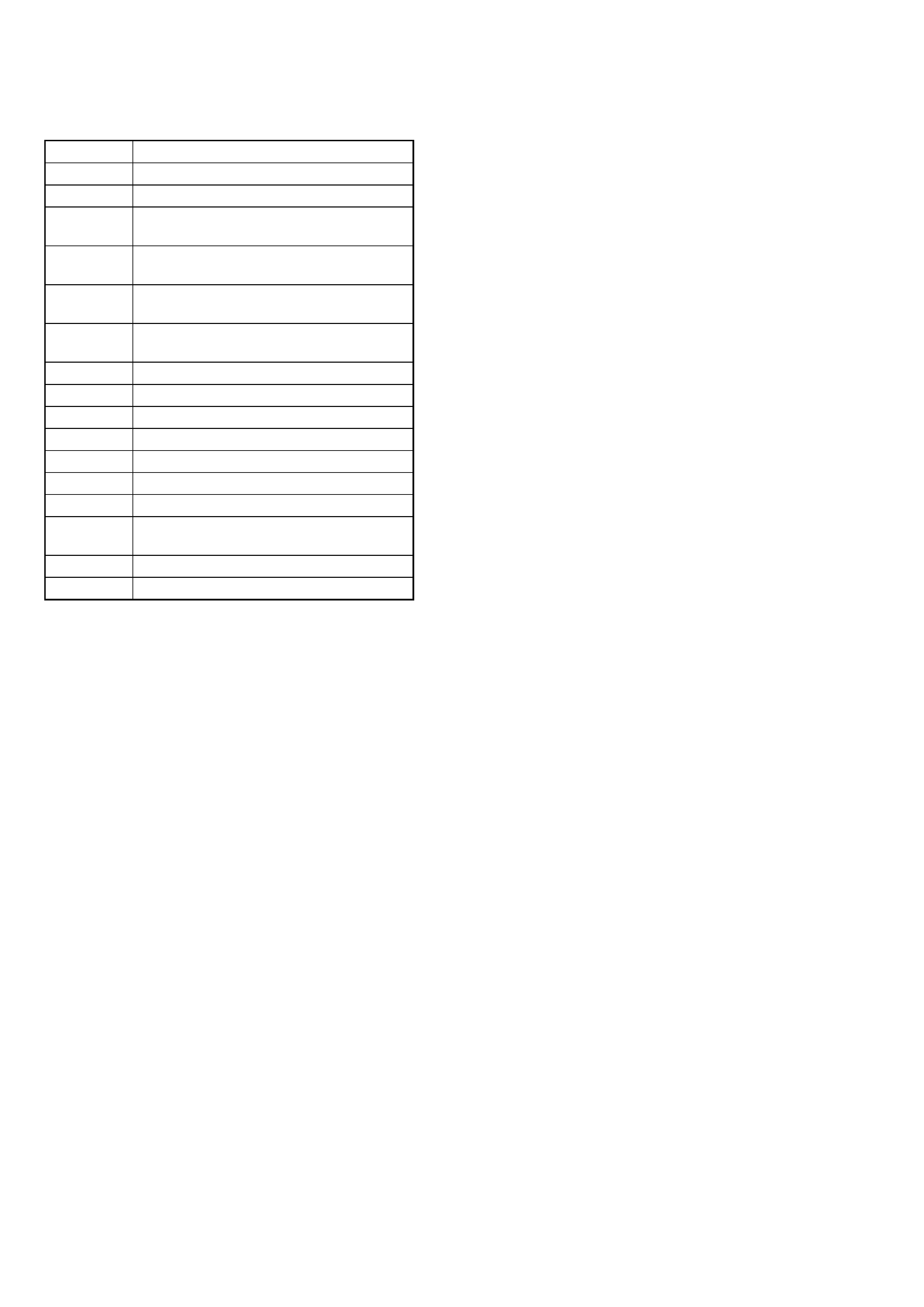
Error Code
Details of Error
10
Loading failed
12
Loading switch combination is illegal
20
Head of PTOC could not be read within the
specified time
21
Head of PTOC could be read but its content is
erroneous
22
Access to UTOC could not be made within the
specified time
23
UTOC could be not read within the specified
3time
24
Content of UTOC is erroneous
30
Playing could not start
31
Content of sector is erroneous
40
Cause of retry occurred during normal recording
41
D-RAM overflowed and retry was executed
42
Retry was executed during the writing to TOC
43
S.F editing was interrupted by retry
50
Address could not be read except in access
processing
51
Focusing failed and it is out of control
60
Unlock retry
Table of Error Codes

5
MXD-D400
SELF-DIAGNOSIS FUNCTION ........................... 2
1.
SERVICING NOTES ............................................... 7
2.
GENERAL ................................................................... 16
3.
DISASSEMBLY
3-1. Disassembly Flow ........................................................... 17
3-2. Case (409538) ................................................................. 18
3-3. Loading Panel (CD) ........................................................ 18
3-4. MD Mechanism Deck (MDM-7S2C) ............................. 19
3-5. CD Mechanism Deck (CDM66C-30B61C) ................... 19
3-6. Transformer Board .......................................................... 20
3-7. Main Board ...................................................................... 20
3-8. Front Panel Block Section .............................................. 21
3-9. Holder Section ................................................................. 21
3-10. Over Write Head (HR901) .............................................. 22
3-11. Optical Pick-up (KMS-262E) ......................................... 22
3-12. BD (MD) Board .............................................................. 23
3-13. Loading Motor Assembly (M103), Spindle Motor
Assembly (M101), Sled Motor Assembly (M102) ........ 23
3-14. Tray (66) .......................................................................... 24
3-15. BD (CD) Board ............................................................... 25
3-16. Optical Block Section ..................................................... 25
4.
TEST MODE .............................................................. 26
5.
ELECTRICAL ADJUSTMENTS
MD Section ..................................................................... 32
CD Section ...................................................................... 44
6.
DIAGRAMS
6-1. Block Diagram CD Section ..................................... 46
6-2. Block Diagram MD Section .................................... 47
6-3. Block Diagram MAIN Section ................................ 48
6-4. Note for Printed Wiring Boards and
Schematic Diagrams ....................................................... 49
6-5. Printed Wiring Board BD (CD) Section .................. 50
6-6. Schematic Diagram BD (CD) Section .................... 51
6-7. Schematic Diagram BD (MD) Board (1/2) ............. 52
6-8. Schematic Diagram BD (MD) Board (2/2) ............. 53
6-9. Printed Wiring Board BD (MD) Board ................... 54
6-10. Printed Wiring Board
MAIN Board (Component Side) .............................. 56
6-11. Printed Wiring Board
MAIN Board (Conductor Side) ................................ 57
6-12. Schematic Diagram MAIN Board (1/4) .................. 58
6-13. Schematic Diagram MAIN Board (2/4) .................. 59
6-14. Schematic Diagram
MAIN (3/4)/LOADING Boards ............................... 60
6-15. Schematic Diagram MAIN Board (4/4) .................. 61
6-16. Printed Wiring Boards Panel Section ...................... 62
6-17. Schematic Diagram Panel Section .......................... 63
6-18. Printed Wiring Board TRANSFORMER Board ..... 64
6-19. Schematic Diagram TRANSFORMER Board ........ 65
6-20. IC Pin Function Description ........................................... 74
7.
EXPLODED VIEWS
7-1. Overall Section ................................................................ 83
7-2. Front Panel Section ......................................................... 84
7-3. Chassis Section ............................................................... 85
7-4. MD Mechanism Deck Section-1 (MDM-7S2C) ............ 86
7-5. MD Mechanism Deck Section-2 (MDM-7S2C) ............ 87
7-6. CD Mechanism Deck Section (CDM66C-30B61M) ..... 88
7-7. Base Unit Section (BU-30BD61M) ................................ 89
8.
ELECTRICAL PARTS LIST ............................... 90
TABLE OF CONTENTS