MICROFILM
SERVICE MANUAL
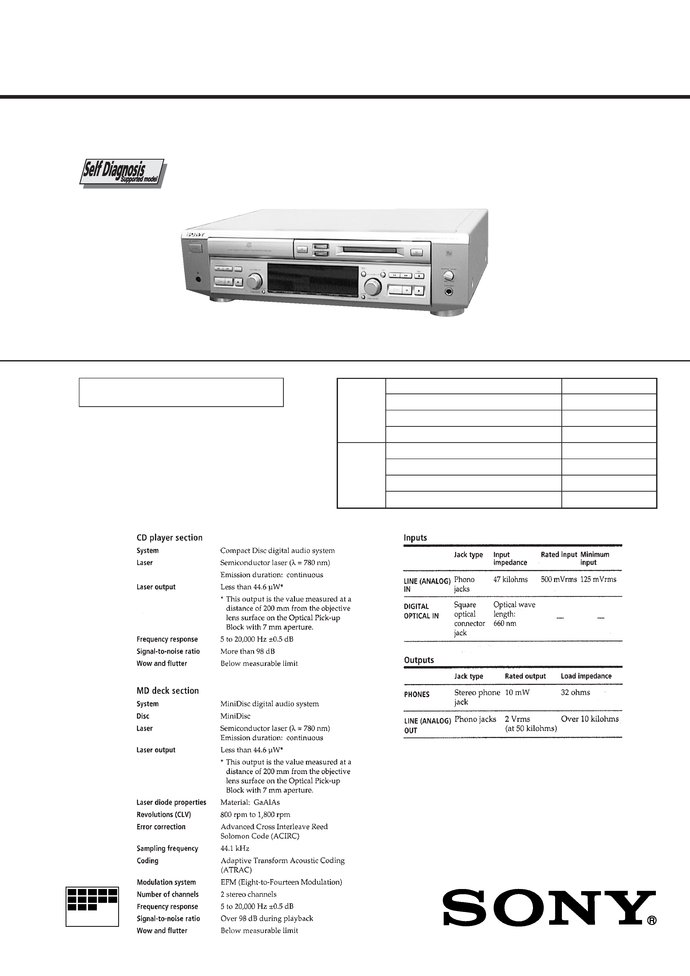
COMPACT DISC MINIDISC DECK
US Model
Canadian Model
AEP Model
UK Model
E Model
Chinese Model
SPECIFICATIONS
MXD-D3
Continued on next page
U.S. and foreign patents licensed form Dolby
Laboratories Licensing Corporation.
Model Name Using Similar Mechanism
NEW
CD Mechanism Type
CDM14H-5TBD26B
Base Unit Name
BU-5TBD26B
Optical Pick-up Name
KSS-213BH/Z-NP
Model Name Using Similar Mechanism
NEW
MD Mechanism Type
MDM-5X2B
Base Unit Name
MBU-5X2B
Optical Pick-up Name
KMS-262A/J1N
CD
Section
MD
Section
Photo: Gold
2
SELF-DIAGNOSIS FUNCTION
The self-diagnosis function consists of error codes for customers which are displayed automatically when errors occur, and error codes
which show the error history in the test mode during servicing. For details on how to view error codes for the customer, refer to the
following box in the instruction manual. For details on how to check error codes during servicing, refer to the following "Procedure for
using the Self-Diagnosis Function (Error History Display Mode)".
PROCEDURE FOR USING THE SELF-DIAGNOSIS FUNCTION (ERROR HISTORY DISPLAY MODE)
Note: Perform the self-diagnosis function in the "error history display mode" in the test mode. The following describes the least required procedure. Be
careful not to enter other modes by mistake. If you set other modes accidentally, press the MENU/NO button to exit the mode.
1. Press the x (CD), [CLEAR] (CD), x (MD) and [CLEAR] (MD) buttons at the same time.
2. Press the [
AMS
] (MD) knob and x (MD) button to display " <0> To Normal".
3. Turn the [
AMS
] (MD) knob and when " <5> MD Test" is displayed, press the [
AMS
] (MD) knob.
4. Turn the [
AMS
] (MD) knob and when "[Service]" is displayed, press the [YES] button.
5. Turn the [
AMS
] (MD) knob to display "ERR DP MODE".
6. Press the [YES] button to sets the error history mode and displays "total rec".
7. Select the contents to be displayed or executed using the [
AMS
] (MD) knob.
8. Press the [
AMS
] (MD) knob to display or execute the contents selected.
9. Press the [
AMS
] (MD) knob another time returns to step 6.
10. Press the [MENU/NO] button to display "ERROR DP MODE" and release the error history mode.
11. To release the test mode, press the ?/1 button to turn the power OFF.
lL
lL
lL
lL
lL
lL
lL
lL
3
ITEMS OF ERROR HISTORY MODE ITEMS AND CONTENTS
Selecting the Test Mode
Display
Details of History
E00
No error
E01
Disc error. PTOC cannot be read
(DISC ejected)
E02
Disc error. UTOC error
(DISC not ejected)
E03
Loading error
E04
Address cannot be read (Servo has deviated)
Table of Error Codes
Error Code
Error Code
Details of Error
total rec
Displays the recording time.
Displayed as "rssssssh".
The displayed time is the total time the laser is set to the high power state.
This is about 1/4 of the actual recording time.
The time is displayed in decimal digits from 0h to 65535h.
total play
Displays the play time.
Displayed as "pssssssh". The time displayed is the total actual play time. Pauses are not counted.
The time is displayed in decimal digits from 0h to 65535h.
retry err
Displays the total number of retries during recording and number of retry errors during play.
Displayed as "rss pss".
"r" indicates the retries during recording while "p" indicates the retry errors during play.
The number of retries and retry errors are displayed in hexadecimal digits from 00 to FF.
total err
Displays the total number of errors.
Displayed as "total ss".
The number of errors is displayed in hexadecimal digits from 00 to FF.
err history
Displays the 10 latest errors.
Displayed as "0s E@@".
s indicates the history number. The smaller the number, the more recent is the error. (00 is the latest).
@@ indicates the error code.
Refer to the following table for the details. The error history can be switched by turning the [
AMS
]
(MD) knob.
er refresh
Mode which erases the "retry err", "total err", and "err history" histories.
When returning the unit to the customer after completing repairs, perform this to erase the past error history.
After pressing the [
AMS
] (MD) knob and "er refresh?" is displayed, press the [YES] button to erase
the history.
"Complete!" will be displayed momentarily.
Be sure to check the following when this mode has been executed.
· The data has been erased.
· The mechanism operates normally when recording and play are performed.
tm refresh
Mode which erases the "total rec" and "total play" histories.
These histories serve as approximate indications of when to replace the optical pick-up.
If the optical pickup has been replaced, perform this operation and erase the history.
After pressing the [
AMS
] (MD) knob and "tm refresh?" is displayed, press the [YES] button to erase
the history.
"Complete!" will be displayed momentarily.
Be sure to check the following when this mode has been executed.
· The data has been erased.
· The mechanism operates normally when recording and play are performed.
E05
FOK has deviated
E06
Cannot focus (Servo has deviated)
E07
Recording retry
E08
Recording retry error
E09
Playback retry error
(Access error)
E0A
Playback retry error (C2 error)
Details of Error
lL
lL
lL
4
SECTION 1
SERVICING NOTES
TABLE OF CONTENTS
SELF-DIAGNOSIS FUNCTION .................................... 2
1.
SERVICING NOTES ............................................... 4
2.
GENERAL ................................................................... 17
3.
DISASSEMBLY ......................................................... 18
4.
TEST MODE .............................................................. 24
5.
ELECTRICAL ADJUSTMENTS ......................... 30
6.
DIAGRAMS
6-1. Note for Printed Wiring Boards and
Schematic Diagrams ....................................................... 41
6-2. Printed Wiring Board BD (CD) Board .................... 42
6-3. Schematic Diagram BD (CD) Board ....................... 43
6-4. Schematic Diagram BD (MD) Board (1/2) ............. 44
6-5. Schematic Diagram BD (MD) Board (2/2) ............. 45
6-6. Printed Wiring Board BD (MD) Board ................... 46
6-7. Schematic Diagram
MAIN (1/3) /LOADING Boards .............................. 47
6-8. Schematic Diagram MAIN Board (2/3) .................. 48
6-9. Schematic Diagram MAIN Board (3/3) .................. 49
6-10. Printed Wiring Board MAIN Board (Side A) ......... 50
6-11. Printed Wiring Boards
MAIN (Side B)/LOADING Boards ......................... 51
6-12. Printed Wiring Boards
DISPLAY/PWSW/HP Boards .................................. 52
6-13. Schematic Diagram
DISPLAY/PWSW/HP Boards .................................. 53
6-14. Printed Wiring Board TRANS Board ...................... 54
6-15. Schematic Diagram TRANS Board ......................... 55
6-16. Printed Wiring Board SW Board ............................. 55
6-17. Schematic Diagram SW Board ................................ 55
6-18. IC Pin Function Description ........................................... 63
7.
EXPLODED VIEWS ................................................ 72
8.
ELECTRICAL PARTS LIST ............................... 79
SAFETY CHECK-OUT
After correcting the original service problem, perform the follow-
ing safety check before releasing the set to the customer:
Check the antenna terminals, metal trim, "metallized" knobs,
screws, and all other exposed metal parts for AC leakage.
Check leakage as described below.
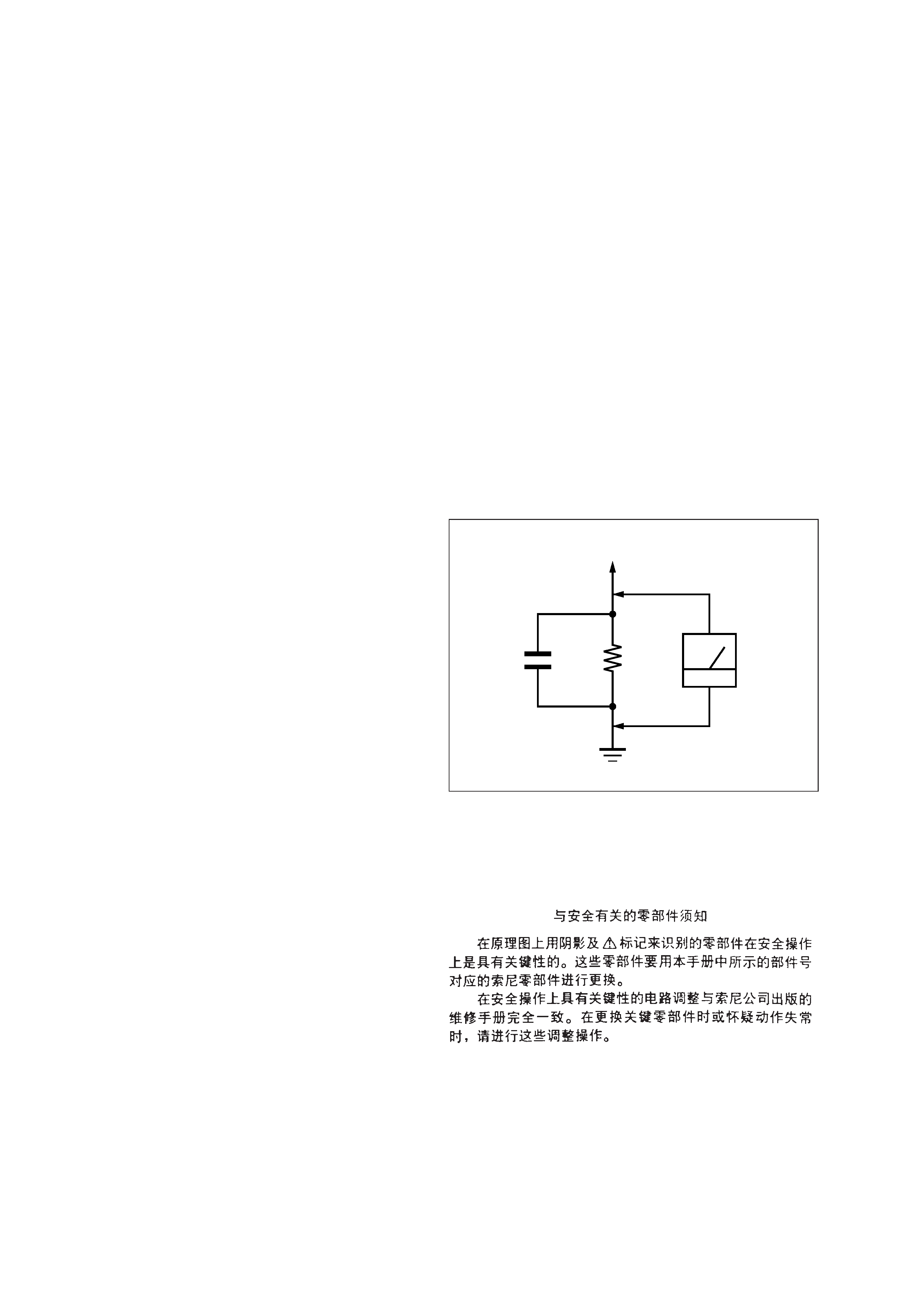
LEAKAGE TEST
The AC leakage from any exposed metal part to earth ground and
from all exposed metal parts to any exposed metal part having a
return to chassis, must not exceed 0.5 mA (500 microamperes.).
Leakage current can be measured by any one of three methods.
1. A commercial leakage tester, such as the Simpson 229 or RCA
WT-540A. Follow the manufacturers' instructions to use these
instruments.
2. A battery-operated AC milliammeter. The Data Precision 245
digital multimeter is suitable for this job.
3. Measuring the voltage drop across a resistor by means of a
VOM or battery-operated AC voltmeter. The "limit" indica-
tion is 0.75 V, so analog meters must have an accurate low-
voltage scale. The Simpson 250 and Sanwa SH-63Trd are ex-
amples of a passive VOM that is suitable. Nearly all battery
operated digital multimeters that have a 2 V AC range are suit-
able. (See Fig. A)
Fig. A.
Using an AC voltmeter to check AC leakage.
1.5 k
0.15
µF
AC
voltmeter
(0.75 V)
To Exposed Metal
Parts on Set
Earth Ground
ATTENTION AU COMPOSANT AYANT RAPPORT
À LA SÉCURITÉ!
LES COMPOSANTS IDENTIFIÉS PAR UNE MARQUE 0
SUR LES DIAGRAMMES SCHÉMATIQUES ET LA LISTE
DES PIÈCES SONT CRITIQUES POUR LA SÉCURITÉ
DE FONCTIONNEMENT. NE REMPLACER CES COM-
POSANTS QUE PAR DES PIÈCES SONY DONT LES
NUMÉROS SONT DONNÉS DANS CE MANUEL OU
DANS LES SUPPLÉMENTS PUBLIÉS PAR SONY.
SAFETY-RELATED COMPONENT WARNING!!
COMPONENTS IDENTIFIED BY MARK 0 OR DOTTED
LINE WITH MARK 0 ON THE SCHEMATIC DIAGRAMS
AND IN THE PARTS LIST ARE CRITICAL TO SAFE
OPERATION. REPLACE THESE COMPONENTS WITH
SONY PARTS WHOSE PART NUMBERS APPEAR AS
SHOWN IN THIS MANUAL OR IN SUPPLEMENTS PUB-
LISHED BY SONY.
5
This appliance is classified as a CLASS 1 LASER product.
The CLASS 1 LASER PRODUCT MARKING is located on
the rear exterior.
Laser component in this product is capable of emitting radia-
tion exceeding the limit for Class 1.
This caution
label is located
inside the unit.
CAUTION
Use of controls or adjustments or performance of procedures
other than those specified herein may result in hazardous ra-
diation exposure.
The laser diode in the optical pick-up block may suffer electro-
static break-down because of the potential difference generated
by the charged electrostatic load, etc. on clothing and the human
body.
During repair, pay attention to electrostatic break-down and also
use the procedure in the printed matter which is included in the
repair parts.
The flexible board is easily damaged and should be handled with
care.
NOTES ON LASER DIODE EMISSION CHECK
The laser beam on this model is concentrated so as to be focused
on the disc reflective surface by the objective lens in the optical
pick-up block. Therefore, when checking the laser diode emis-
sion, observe from more than 30 cm away from the objective lens.
LASER DIODE AND FOCUS SEARCH OPERATION
CHECK
Carry out the "S curve check" in "CD section adjustment" and
check that the S curve waveforms is output three times.
NOTES ON HANDLING THE OPTICAL PICK-UP
BLOCK OR BASE UNIT
ADVARSEL
Eksplosjonsfare ved feilaktig skifte av batteri.
Benytt samme batteritype eller en tilsvarende type
anbefalt av apparatfabrikanten.
Brukte batterier kasseres i henhold til fabrikantens
instruksjoner.
VARNING
Explosionsfara vid felaktigt batteribyte.
Använd samma batterityp eller en likvärdig typ som
rekommenderas av apparattillverkaren.
Kassera använt batteri enligt gällande föreskrifter.
VAROITUS
Paristo voi räjähtää, jos se on virheellisesti asennettu.
Vaihda paristo ainoastaan laitevalmistajan suosittelemaan tyyppiin.
Hävitä käytetty paristo valmistajan ohjeiden mukaisesti.
Flexible Circuit Board Repairing
· Keep the temperature of the soldering iron around 270 °C dur-
ing repairing.
· Do not touch the soldering iron on the same conductor of the
circuit board (within 3 times).
· Be careful not to apply force on the conductor when soldering
or unsoldering.
Notes on chip component replacement
· Never reuse a disconnected chip component.
· Notice that the minus side of a tantalum capacitor may be dam-
aged by heat.
ADVARSEL!
Lithiumbatteri-Eksplosionsfare ved fejlagtig håndtering.
Udskiftning må kun ske med batteri
af samme fabrikat og type.
Levér det brugte batteri tilbage til leverandøren.
CAUTION
Danger of explosion if battery is incorrectly replaced.
Replace only with the same or equivalent type recommended by
the manufacturer.
Discard used batteries according to the manufacturer's instruc-
tions.
Note:
Be sure to connect all wires (including FFC) in the MD
section before applying power or ICs may be damaged.