SERVICE MANUAL
Ver. 1.0 2001. 02
DIGITAL STILL CAMERA
MVC-FD87/FD92
US Model
Canadian Model
AEP Model
UK Model
E Model
Hong Kong Model
Australian Model
Korea Model
Japanese Model
Level 2
SPECIFICATIONS
This service manual contains information for Japanese model as well.
On the FC-85 board
This service manual procides the information that is premised the
circuit board replacement service and not intended repair inside the
FC-85 board.
Therefore, schematic diagram, printed wiring board and electrical
parts list of the FC-85 board is not shown.
The following pages are not shown.
FC-85 board
Schematic diagram ..................................... Page 4-15 to 4-38
Printed wiring board ................................... Page 4-11 to 4-14
Electrical parts list ...................................... Page 6-10 to 6-18
The above-described information is shown in service manual
Level 3.
When the machine needs to be repaired,
please refer to page 7 to discriminate the
type of LCD.
PHoto: MVC-FD92
System
Image device
5m
FD92:
FD92:
FD87:
m(1/3.6type) colorCCD
6.64 mm (1/2.7 type) color CCD
Lens
8
× zoom lens
f = 4.75 38 mm (3/16
1 1/2 inches)
(41 328 mm (1 5/8 13 inches)
when converted into a 35 mm still
camera)
F = 2.8 3.0
FD87: 3
× zoom lens
f = 6.1 18.3 mm (1/4 3/4 inches)
(39 117 mm (1 9/16 4 5/8 inches)
when converted into a 35 mm still
camera)
F = 2.8 2.9
Exposure control
Automatic exposure
White balance
Automatic, Indoor, Outdoor, Hold
Data system
Mo
FD92:
vie: MPEG
Still: JPEG, GIF (in TEXT
mode, Clip Motion), TIFF
Audio with still image:
MPEG (Monaural)
GIF (in TEXT mode)
FD87:
Floppy disk: JPEG (JFIF)
"Memory Stick": JPEG
(Exif2.1)
Recording medium
Fl
FD92:
oppy disk:
3.5 inch 2HD MS-DOS
format (1.44 MB)
"Memory Stick"
Fl
FD87:
oppy disk:
3.5 inch 2HD MS-DOS
format (1.44 MB)
"Memory Stick" (When using with
the MSAC-FD2M/FD2MA Floppy
Disk Adaptor for Memory Stick):
DCF format
Flash
Recommended recording
distance:
0.3mto2.5m(11 7/8inches
to 8 1/3 feet)
Input and Output
connector (FD92)
A/V OUT (MONO)
(Monaural)
Minijack Video:
1 Vp-p, 75
, unbalanced,
sync negative
Audio: 327 mV (at a 47 k
load)
Output impedance: 2.2 k
ACC jack
Minijack
USB jack
mini-B
Continued on next page

2
1. Check the area of your repair for unsoldered or poorly-sol-
dered connections. Check the entire board surface for solder
splashes and bridges.
2. Check the interboard wiring to ensure that no wires are
"pinched" or contact high-wattage resistors.
3. Look for unauthorized replacement parts, particularly transis-
tors, that were installed during a previous repair. Point them
out to the customer and recommend their replacement.
SAFETY CHECK-OUT
After correcting the original service problem, perform the following
safety checks before releasing the set to the customer.
4. Look for parts which, though functioning, show obvious signs
of deterioration. Point them out to the customer and recom-
mend their replacement.
5. Check the B+ voltage to see it is at the values specified.
6. Flexible Circuit Board Repairing
·
Keep the temperature of the soldering iron around 270 °C
during repairing.
·
Do not touch the soldering iron on the same conductor of
the circuit board (within 3 times).
·
Be careful not to apply force on the conductor when sol-
dering or unsoldering.
ATTENTION AU COMPOSANT AYANT RAPPORT
À LA SÉCURITÉ!
LES COMPOSANTS IDENTIFIÉS PAR UNE MARQUE 0
SUR LES DIAGRAMMES SCHÉMATIQUES ET LA LISTE
DES PIÈCES SONT CRITIQUES POUR LA SÉCURITÉ
DE FONCTIONNEMENT. NE REMPLACER CES COM-
POSANTS QUE PAR DES PIÈCES SONY DONT LES
NUMÉROS SONT DONNÉS DANS CE MANUEL OU
DANS LES SUPPLÉMENTS PUBLIÉS PAR SONY.
SAFETY-RELATED COMPONENT WARNING!!
COMPONENTS IDENTIFIED BY MARK 0 OR DOTTED
LINE WITH MARK 0 ON THE SCHEMATIC DIAGRAMS
AND IN THE PARTS LIST ARE CRITICAL TO SAFE
OPERATION. REPLACE THESE COMPONENTS WITH
SONY PARTS WHOSE PART NUMBERS APPEAR AS
SHOWN IN THIS MANUAL OR IN SUPPLEMENTS PUB-
LISHED BY SONY.
LCD screen
LCD panel
TFT (Thin Film Transistor
active matrix) drive
Total number of dots
123 200 (560
×220) dots
General
Application
Sony battery pack NP-F330
(supplied)/F550
Power requirements
8.4 V
Power consumption
(During shooting)
3.5 W
Operating temperature
0
°Cto40°C(32°Fto104°F)
Storage temperature
20
°Cto+60°C(4°Fto
+140
°F)
Dimensions (Approx.)
143
×
FD92:
FD92:
103
×79 mm
(5 3/4
×41/8×3 1/8 inches)
(w/h/d)
143
×
FD87:
103
×75 mm
(5 3/4
×41/8×3 inches)
(w/h/d)
Mass (Approx.)
660g(1lb7oz) (including
NP-F330 battery pack,
floppy disk and lens cap, etc.)
FD87: 630 g (1 lb 6 oz) (including
NP-F330 battery pack,
floppy disk and lens cap, etc.)
Built-in microphone (FD92)
Electret condenser
microphone
Built-in speaker (FD92)
Dynamic speaker
AC-L10A/L10B/L10C
AC power adaptor
Power requirements
100 to 240 V AC, 50/60 Hz
Rated output voltage
DC 8.4 V, 1.5 A in operating
mode
Operating temperature
0
°Cto40°C(32°Fto104°F)
Storage temperature
20
°Cto+60°C(4°Fto +140°F)
Dimensions (Approx.)
125
×39×62 mm (5×19/16×2 1/2 inches)
(w/h/d)
Mass (Approx.)
280 g (10 oz)
NP-F330 battery pack
Battery type
Lithium ion
Maximum output
voltage
DC 8.4 V
Mean output voltage
DC 7.2 V
Capacity
5.0 Wh (700 mAh)
Operating temperature
0
°Cto40°C(32°F to 104°F)
Dimensions (Approx.)
38.4 20.6 70.8 mm
(1 9/16 13/16 2 7/8 inches)
(w/h/d)
Mass (Approx.)
70 g (2 oz)
Accessories
AC-L10A/L10B/L10C
AC power adaptor (1)
Power cord (mains lead) (1)
USB cable (1) (FD92)
NP-F330 battery pack (1)
A/V connecting cable (1) (FD92)
Shoulder strap (1)
Lens cap (1)
Lens cap strap (1)
CD-ROM (SPVD-004 USB Driver) (1)
Operating instructions (1)
Design and specifications are subject to change
without notice.
3
· Floppy disk that can be used by the MVC-FD87/FD92
· Size :
3.5-inch
· Type :
2 HD
· Capacity :
1.44 MB
· Format :
MS-DOS format
(512 bytes
× 18 sector)
(FD can be formatted by the MVC-FD87/FD92)
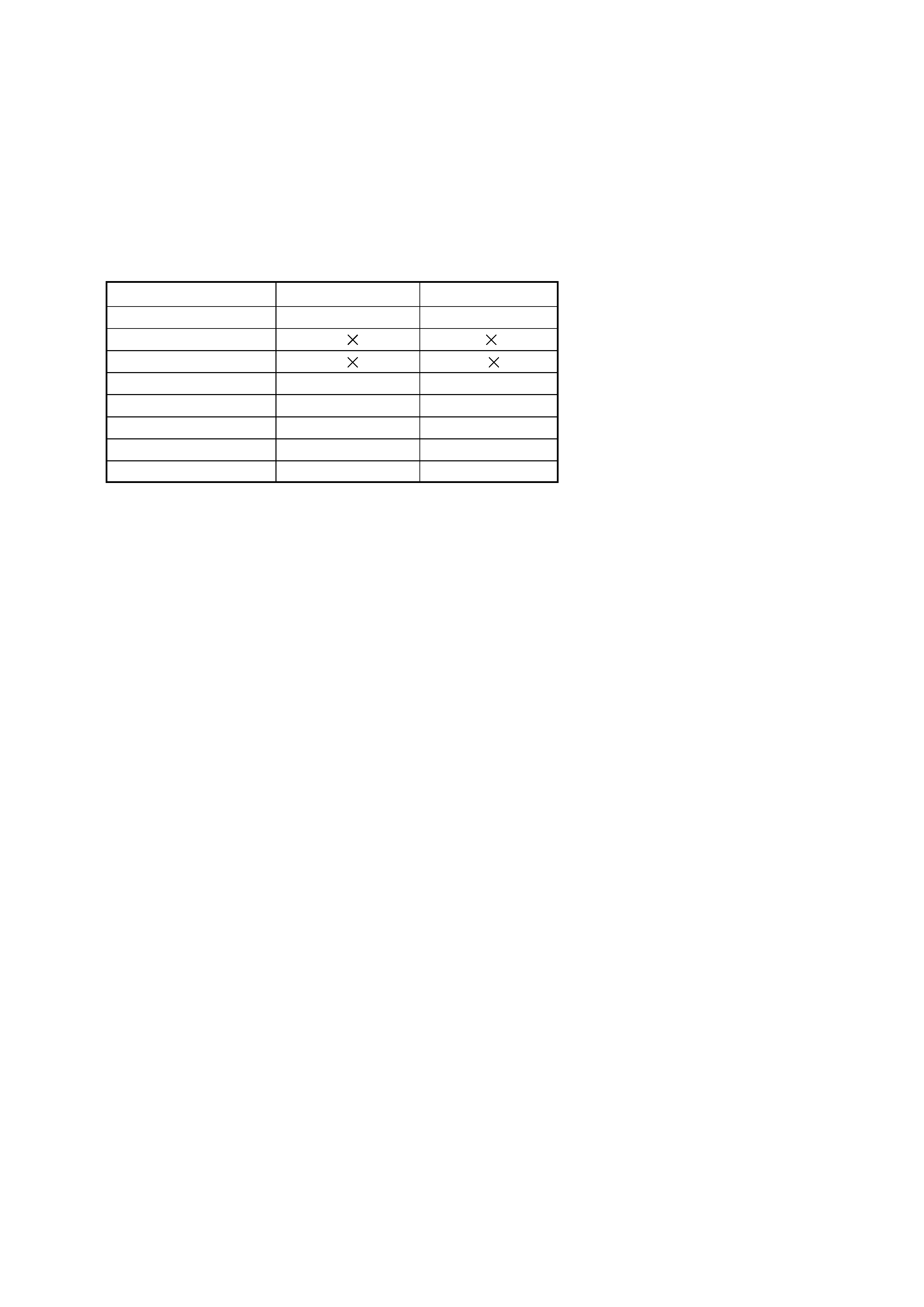
Table for differences of function
Model
MVC-FD87
MVC-FD92
Image device
1/2.7-inch CCD
1/3.6-inch CCD
Lens
3
8
Digital zoom
6
16
Recording moving image
a
Audio with still image
a
MS socket
a
Digital I/O (USB)
a
CD board
CD-318
CD-310

4
SERVICE NOTE ................................................................... 6
Self-diagnosis Display ............................................................. 8
1.
GENERAL
Introduction .............................................................................. 1-1
Identifying the Parts ................................................................. 1-2
Preparing the Power Supply ................................................... 1-2
Setting the Date and Time ....................................................... 1-3
Inserting a Floppy Disk ............................................................ 1-4
Inserting a "Memory Stick" ..................................................... 1-4
Recording Still Images ............................................................ 1-4
Recording Moving Images ...................................................... 1-6
Playing Back Still Images ........................................................ 1-6
Playing Back Moving Images .................................................. 1-6
Viewing Images Using a Computer ......................................... 1-7
Image File Storage Destinations and Image File Names ....... 1-8
Before Performing Advanced Operations ............................... 1-9
Various Recording ................................................................... 1-11
Various Playback ..................................................................... 1-15
Editing ..................................................................................... 1-16
As an External Drive ................................................................ 1-18
Additional Information ............................................................. 1-18
Troubleshooting ....................................................................... 1-19
Warning and Notice Messages ............................................... 1-21
Self-diagnosis Display ............................................................. 1-21
LCD Screen Indicators ............................................................ 1-21
2.
DISASSEMBLY
2-1.
Cabinet (Rear) Block Assembly .................................... 2-1
2-2.
FDD Block Assembly ..................................................... 2-1
2-3.
FC-85 Board .................................................................. 2-2
2-4.
Lens Block Assembly .................................................... 2-2
2-5.
PK-54 Board .................................................................. 2-3
2-6.
LCD Module ................................................................... 2-3
2-7.
Circuit Boards Location ................................................. 2-4
3.
BLOCK DIAGRAMS
3-1.
Overall Block Diagram .................................................. 3-1
3-9.
Power Block Diagram 1 ................................................. 3-17
3-10. Power Block Diagram 2 ................................................. 3-19
4.
PRINTED WIRING BOARDS AND
SCHEMATIC DIAGRAMS
4-1.
Frame Schematic Diagrams ......................................... 4-3
Frame Schematic Diagram (1/2) ................................... 4-3
Frame Schematic Diagram (2/2) ................................... 4-5
4-2.
Printed Wiring Boards and Schematic Diagrams ......... 4-7
CD-310 Printed Wiring Board and
Schematic Diagram ....................................................... 4-7
CD-318 Printed Wiring Board and
Schematic Diagram ....................................................... 4-9
FU-152 Printed Wiring Board ....................................... 4-39
FU-152 Schematic Diagram ......................................... 4-41
PK-54 Printed Wiring Board .......................................... 4-43
PK-54 (MODE SWITCH, A/V OUT)
Schematic Diagram ....................................................... 4-47
PK-54 (LCD DRIVE, TIMING GENERATOR)
Schematic Diagram ....................................................... 4-49
PK-54 (BACK LIGHT DRIVE) Schematic Diagram ...... 4-51
4-3.
Waveforms .................................................................... 4-53
4-4.
Parts Location ............................................................... 4-56
TABLE OF CONTENTS
Section
Title
Page
Section
Title
Page
5.
ADJUSTMENTS
Before Starting Adjustment ..................................................... 5-1
1-1.
Adjusting Items when Replacing
Main Parts and Boards .................................................. 5-2
5-1.
Camera Section Adjustments ........................................ 5-3
1-1.
Preparations Before Adjustment ................................... 5-3
1-1-1. List of Service Tools ................................................. 5-3
1-1-2. Preparations ............................................................. 5-4
1-1-3. Discharging of the Flashlight Power Supply ............ 5-4
1-1-4. Precautions .............................................................. 5-6
1. Setting the Switch .................................................... 5-6
2. Order of Adjustments ............................................... 5-6
3. Subjects .................................................................... 5-6
4. Preparing the Flash Adjustment Box ....................... 5-7
1-2.
Initialization of B, D, E, F, 7 Page Data ........................ 5-8
1-2-1. Initialization of D Page Data .................................... 5-8
1. Initializing D Page Data ............................................ 5-8
2. Modification of D Page Data .................................... 5-8
3. D Page Table ............................................................ 5-9
1-2-2. Initialization of B, E, F, 7 Page Data ........................ 5-10
1. Initializing B, E, F, 7 Page Data ............................... 5-10
2. Modification of B, E, F, 7 Page Data ........................ 5-10
3. B Page Table ............................................................ 5-10
4. E Page Table ............................................................ 5-10
5. F Page Table ............................................................ 5-11
6. 7 Page Table ............................................................ 5-13
1-3.
Video System Adjustments ........................................... 5-14
1.
Video Sync Level Adjustment (FD92) ........................... 5-14
2.
Video Burst Level Adjustment (FD92) .......................... 5-14
1-4.
Camera System Adjustment ......................................... 5-15
1.
Hall Adjustment ............................................................. 5-16
2.
Flange Back Adjustment (Using the Minipattern Box) .. 5-17
3.
Flange Back Adjustment (Using the Flange Back
Adjustment Chart Subject More than 500 m Away) ..... 5-18
4.
Flange Back Check ....................................................... 5-20
5.
F No. Standard Data Input ............................................ 5-20
6.
Mechanical Shutter Adjustment .................................... 5-21
7.
Picture Frame Setting ................................................... 5-22
8.
Light Level Adjustment and ND Shutter Check ............ 5-23
9.
Mixed Color Cancel Adjustment .................................... 5-24
10. Auto White Balance Standard Data Input ..................... 5-24
11. Auto White Balance ND Filter Compensation (FD92) .. 5-25
12. Auto White Balance Adjustment ................................... 5-26
13. Color Reproduction Adjustment .................................... 5-27
14. Color Reproduction Check ............................................ 5-28
15. Auto White Balance Check ........................................... 5-30
16. Strobe White Balance Adjustment ................................ 5-32
17. Strobe Light Level and White Balance Check .............. 5-33
18. CCD Black Defect Compensation ................................. 5-34
19. CCD White Defect Compensation ................................ 5-35
1-5.
LCD System Adjustments ............................................. 5-36
1.
LCD Initial Data Input .................................................... 5-37
2.
VCO Adjustment (FC-85 Board) ................................... 5-38
3.
Black Limit Adjustment (FC-85 Board) ......................... 5-39
4.
Bright Adjustment (FC-85 Board) .................................. 5-39
5.
Contrast Adjustment (FC-85 Board) ............................. 5-40
6.
Color Adjustment (FC-85 Board) .................................. 5-40
7.
VG Center Adjustment (FC-85 Board) .......................... 5-41
8.
V-COM Adjustment (FC-85 Board) ............................... 5-42
9.
White Balance Adjustment (FC-85 Board) ................... 5-43
1-6.
System Control System Adjustments ........................... 5-44
1.
Battery Down Adjustment .............................................. 5-44
2.
ZOOM Center Adjustment ............................................. 5-45
3.
Alignment Check (FDD Unit) ......................................... 5-45
5-2.
Service Mode ................................................................ 5-46
2-1.
Adjusting Remote Commander ..................................... 5-46
1.
Used the Adjusting Remote Commander ..................... 5-46
2.
Precautions upon Using the Adjusting
Remote Commander ..................................................... 5-46
2-2.
Data Process ................................................................. 5-47
2-3.
Service Mode ................................................................ 5-48
1.
Setting the Test Mode ................................................... 5-48
2.
Bit Value Discrimination ................................................ 5-48

5
Section
Title
Page
3.
Switch Check (1) ........................................................... 5-48
4.
Switch Check (2) (FD92) ............................................... 5-48
5.
Switch Check (3) ........................................................... 5-49
6.
LED Check .................................................................... 5-49
7.
Self Diagnosis Code ...................................................... 5-49
6.
REPAIR PARTS LIST
6-1.
Exploded Views ............................................................. 6-1
6-1-1. Cabinet (Front) Section ............................................ 6-1
6-1-2. Cabinet (Front) Assembly ........................................ 6-2
6-1-3. FDD Block Section ................................................... 6-3
6-1-4. Cabinet (Rear) Section ............................................ 6-4
6-1-5. Cabinet (Rear) Assembly ......................................... 6-5
6-1-6. Lens Block Section (FD87) ...................................... 6-6
6-1-7. Lens Block Section (FD92) ...................................... 6-7
6-2.
Electrical Parts List ........................................................ 6-8
* The color reproduction frame is shown on page 137.