MVC-CD200/CD300
US Model
Canadian Model
AEP Model
UK Model
E Model
Hong Kong Model
Australian Model
Chinese Model
Tourist Model
Korea Model
Japanese Model
SERVICE MANUAL
DIGITAL STILL CAMERA
This service manual contains information for japanese model as well.
Level 2
SPECIFICATIONS
On the SY-67 board and the DDX-G2100 COMPLETE ASSEMBLY (Including the MD-083 Board)
This service manual provides the information on the premised of the circuit board replacement service and not intended
repair inside the SY-67 board in case of trouble. It is also premised that the mechanism deck DDX-G2100 COMPLETE
ASSEMBLY (including the MD-083 board) shall be exchanged as an assembly in case of trouble.
Therefore, disassembling procedure and exploded view of the DDX-G2100 COMPLETE ASSEMBLY are not shown. The
block diagram, printed wiring board, schematic diagram and electrical parts list of the SY-67 board are also not shown.
Note that the following pages are lacking intentionally.
The above-described information is shown in service manual Level 3.
SY-67 board
Block diagram ............................... Page 3-15 to 3-20
Printed wiring board ..................... Page 4-19 to 4-22
Schematic diagram ....................... Page 4-23 to 4-42
Electrical parts list ........................ Page 6-18 to 6-24
DDX-G2100 COMPLETE ASSEMBLY
Disassembly ................................. Page 2-15 to 2-16
Exploded view .............................. Page 6-8
MD-083 board
Block diagram ............................ Page 3-21 to 3-26
Printed wiring board ................... Page 4-43 to 4-46
Schematic diagram .................... Page 4-47 to 4-54
Electrical parts list ...................... Page 6-14 to 6-18
-- Continued on next page --
System
Image device
MVC-CD200: 6.64 mm
(1/2.7 type) color CCD
MVC-CD300: 8.93 mm
(1/1.8 type) color CCD
Lens
3
× zoom lens
MVC-CD200: f = 6.1
18.3 mm (1/4 3/4 inches)
(39 117 mm (1 9/16
4 5/8 inches) when
converted into a 35 mm still
camera)
MVC-CD300: f = 7 21 mm
(9/32 27/32 inches) (34
102 mm (1 3/8
4 1/8 inches) when
converted into a 35 mm still
camera)
MVC-CD200: F = 2.8 2.9
MVC-CD300: F = 2.0 2.5
Exposure control
Automatic exposure, Shutter
speed priority, Aperture
priority, Manual exposure
White balance
Automatic, Indoor, Outdoor,
One-push
Data system
Movie: MPEG1
Still: JPEG, GIF (in TEXT
mode, Clip Motion), TIFF
Audio with still image:
MPEG1 (Monaural)
Recording medium
8 cm CD-R/CD-RW
Recommended flash
recording distance (ISO
is set to AUTO):
MVC-CD200:0.3 mto
2.5 m (11 7/8 inches to
8 1/3 feet)
MVC-CD300:0.3 mto
3 m (11 7/8 inches to 9 feet
10 1/8 inches)
Drive
Read: Maximum
×8
Write:
×4
Readout
Noncontact optical readout
(using semiconductor laser)
Laser
Wavelength: 777 to 787 nm
NA: 0.5
Maximum output: 23 mW
Emission duration: 600 ns
Input and Output
connector
A/V OUT (MONO)
(Monaural)
Minijack Video:
1 Vp-p, 75
, unbalanced,
sync negative
Audio: 327 mV (at a 47 k
load)
Output impedance: 2.2 k
ACC jack
Mini-minijack (Ø 2.5 mm)
USB jack
mini-B
LCD screen
LCD panel
TFT (Thin Film Transistor
active matrix) drive
LCD size
2.5 type
Total number of dots
123 200 (560
×220) dots
General
Application
Sony battery pack NP-FM50
(supplied)
Power requirements
7.2 V
Power consumption
(During shooting with
the LCD backlight
turned on)
MVC-CD200: 3.0 W
MVC-CD300: 3.5 W
Operating temperature
0
°Cto 40°C(32°Fto 104°F)
Photo : MVC-CD300
Ver 1.1 2004. 09
-- 2 --
SAFETY-RELATED COMPONENT WARNING!!
COMPONENTS IDENTIFIED BY MARK 0 OR DOTTED LINE WITH
MARK 0 ON THE SCHEMATIC DIAGRAMS AND IN THE PARTS
LIST ARE CRITICAL TO SAFE OPERATION. REPLACE THESE
COMPONENTS WITH SONY PARTS WHOSE PART NUMBERS
APPEAR AS SHOWN IN THIS MANUAL OR IN SUPPLEMENTS
PUBLISHED BY SONY.
ATTENTION AU COMPOSANT AYANT RAPPORT
À LA SÉCURITÉ!
LES COMPOSANTS IDENTIFÉS PAR UNE MARQUE 0 SUR LES
DIAGRAMMES SCHÉMATIQUES ET LA LISTE DES PIÈCES SONT
CRITIQUES POUR LA SÉCURITÉ DE FONCTIONNEMENT. NE
REMPLACER CES COMPOSANTS QUE PAR DES PIÈSES SONY
DONT LES NUMÉROS SONT DONNÉS DANS CE MANUEL OU
DANS LES SUPPÉMENTS PUBLIÉS PAR SONY.
1.
Check the area of your repair for unsoldered or poorly-soldered
connections. Check the entire board surface for solder splashes
and bridges.
2.
Check the interboard wiring to ensure that no wires are
"pinched" or contact high-wattage resistors.
3.
Look for unauthorized replacement parts, particularly
transistors, that were installed during a previous repair. Point
them out to the customer and recommend their replacement.
4.
Look for parts which, through functioning, show obvious signs
of deterioration. Point them out to the customer and
recommend their replacement.
5.
Check the B+ voltage to see it is at the values specified.
6.
Flexible Circuit Board Repairing
· Keep the temperature of the soldering iron around 270°C
during repairing.
· Do not touch the soldering iron on the same conductor of the
circuit board (within 3 times).
· Be careful not to apply force on the conductor when soldering
or unsoldering.
SAFETY CHECK-OUT
After correcting the original service problem, perform the following
safety checks before releasing the set to the customer.
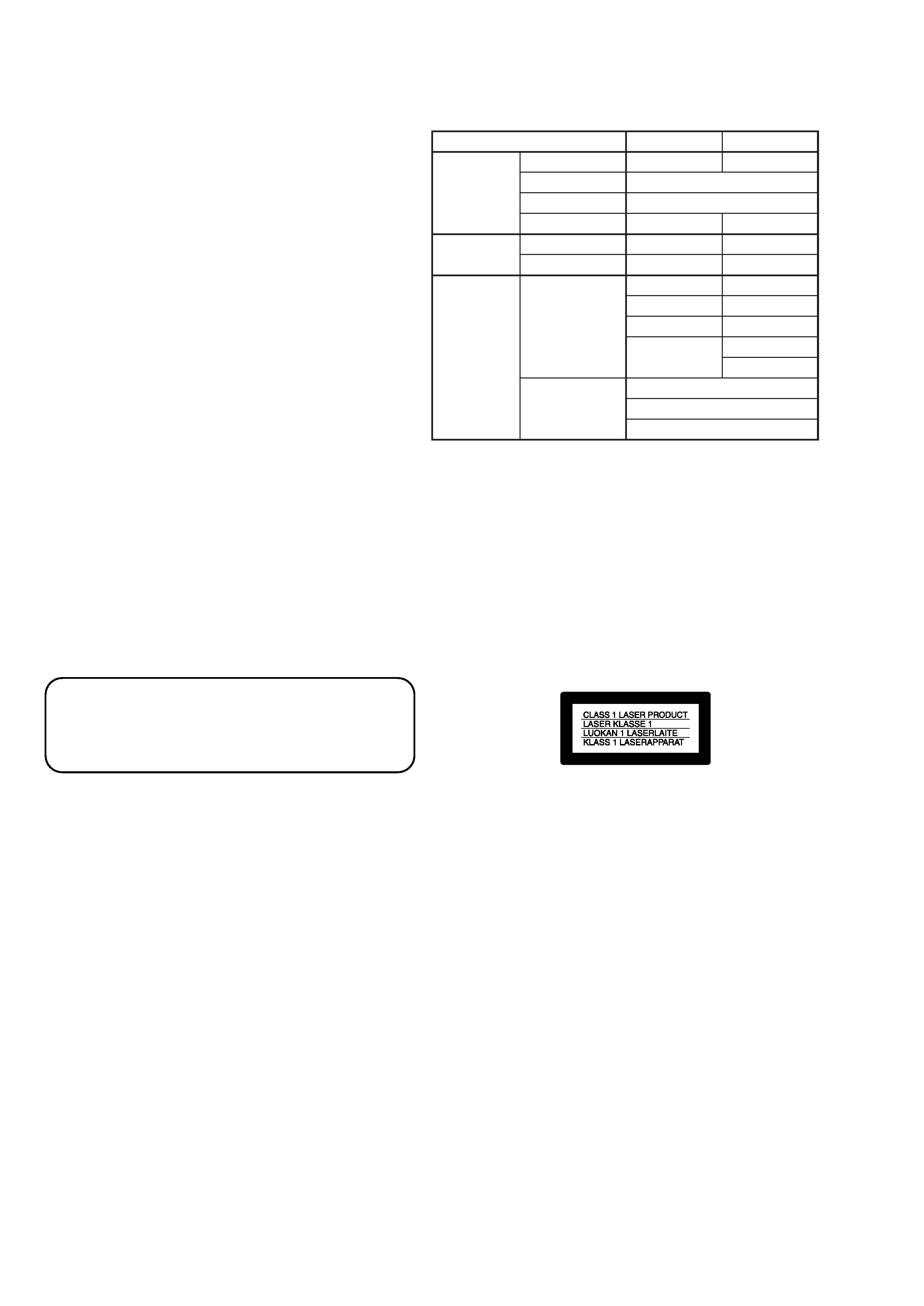
CAUTION
Use of controls or adjustments or performance
procedures other than those specified herein may
result in hazardous radiation exposure.
Storage temperature
20
°Cto +60°C(4°Fto
+140
°F)
Dimensions (Approx.)
MVC-CD200: 143
×92×
89 mm (5 3/4
×35/8×
3 5/8 inches) (w/h/d)
MVC-CD300: 143
×92×
94 mm (5 3/4
×35/8×
3 3/4 inches) (w/h/d)
Mass (Approx.)
MVC-CD200: 610 g
(1 lb6oz)
MVC-CD300: 650 g
(1 lb 7 oz) (including NP-
FM50 battery pack, disc and
lens cap, etc.)
Built-in microphone
Electret condenser
microphone
Built-in speaker
Dynamic speaker
AC-L10A/L10B/L10C
AC power adaptor
Power requirements
100 to 240 V AC, 50/60 Hz
Rated output voltage
DC 8.4 V, 1.5 A in operating
mode
Operating temperature
0
°Cto 40°C(32°F to 104°F)
Storage temperature
20
°Cto +60°C(4°Fto
+140
°F)
Dimensions (Approx.)
125
×39×62 mm (5×19/16×
2 1/2 inches) (w/h/d)
Mass (Approx.)
280g (10oz)
NP-FM50 battery pack
Battery type
Lithium ion
Maximum output
voltage
DC 8.4 V
Mean output voltage
DC 7.2 V
Capacity
8.5 Wh (1180 mAh)
Operating temperature
0
°Cto 40°C(32°F to 104°F)
Dimensions (Approx.)
38.2
×20.5×55.6 mm
(1 9/16
×13/16×2 1/4 inches)
(w/h/d)
Mass (Approx.)
76 g (3 oz)
Accessories
AC-L10A/L10B/L10C
AC power adaptor (1)
Power cord (mains lead) (1)
FerriteCore(1)
USB cable (1)
NP-FM50 battery pack (1)
A/V connecting cable (1)
8 cm CD adaptor (1)
Mavica disc (2) (CD-R (1),
CD-RW (1))
Shoulder strap (1)
Lens cap (1)
Lens cap strap (1)
CD-ROM (2)
O
2-pin conversion adaptor (1)
(E, Hong Kong, Tourist model
perating instructions (2)
Design and specifications
are subject to change
without notice.
only)
Table for difference of functions
Model
Lens
Carl Zeiss lens
Optical zoom
Digital zoom
Filter diameter
CCD imager
Size
Pixels
Image size
Still
Movie
MVC-CD200
37mm
1/2.7 type
2.1mega
1600
×1200
1600 (3:2)
1024
×768
640
×480
MVC-CD300
a
52mm
1/1.8 type
3.3mega
2048
×1536
2048 (3:2)
1600
×1200
1280
×960
640
×480
3
×
6
×
320 (HQ)
320
×240
640
×480

-- 3 --
TABLE OF CONTENTS
SERVICE NOTE ····································································· 6
1.
GENERAL
Introduction ··········································································· 1-1
Getting started
Identifying the parts ······························································· 1-1
Preparing the power supply ··················································· 1-1
Setting the date and time ························································ 1-3
Inserting a disc ······································································· 1-3
Basic operations
B Recording
Initializing a disc (INITIALIZE) ··········································· 1-4
Recording still images ··························································· 1-4
Recording moving images ····················································· 1-6
B Playback
Playing back still images ······················································· 1-6
Playing back moving images ················································· 1-6
Preparation for viewing images using a computer ················· 1-7
Viewing images using a computer ········································· 1-8
Image file storage destinations and image file names ········· 1-10
Advanced operations
Before performing advanced operations
How to use the mode dial ···················································· 1-10
How to use the control button ·············································· 1-11
How to use the jog dial ························································ 1-11
Menu settings ······································································· 1-11
Setting the image size (IMAGE SIZE) ································ 1-12
B Various recording
Recording with the exposure fixed (AE LOCK) ················· 1-13
Recording with the manual adjustments ······························ 1-13
Recording images according to shooting conditions
(SCENE SELECTION) ······················································· 1-14
Recording three images continuously (BURST)
(only for MVC-CD300) ······················································· 1-14
Recording still images for e-mail (E-MAIL) ······················ 1-14
Adding audio files to still images (VOICE) ························ 1-14
Recording text documents (TEXT) ····································· 1-14
Recording still images as uncompressed files (TIFF) ········· 1-15
Recording three images with the exposure shifted
(only for MVC-CD300) (EXP BRKTG) ····························· 1-15
Creating Clip Motion Files ·················································· 1-15
Setting the distance to the subject ········································ 1-16
Recording images in macro ················································· 1-16
Adjusting the exposure (EXPOSURE) ································ 1-16
Adjusting the white balance (WHITE BALANCE) ············ 1-16
Enjoying picture effects (P. EFFECT) ································· 1-16
Recording the date and time on the still image
(DATE/TIME) ······································································ 1-17
Using the Spot light-metering function ······························· 1-17
B Various playback
Playing back three or nine images at once ··························· 1-17
Enlarging a part of the still image (Zoom and trimming) ···· 1-17
Playing back the still images in order (SLIDE) ··················· 1-18
Rotating a still image (ROTATE) ········································· 1-18
Viewing images on a TV screen ·········································· 1-18
B Editing
Deleting images (DELETE) ················································ 1-18
Preventing accidental erasure (PROTECT) ························· 1-19
Changing the recorded still image size (RESIZE) ··············· 1-19
Selecting still images to print (PRINT) ······························· 1-19
Formatting a CD-RW ··························································· 1-20
Changing the setup settings (SET UP) ································ 1-20
Additional information
Precautions ··········································································· 1-21
On discs ··············································································· 1-21
Using your camera abroad ··················································· 1-22
About "InfoLITHIUM" battery pack ·································· 1-22
Troubleshooting ··································································· 1-22
Warning and notice messages ·············································· 1-24
Self-diagnosis display ·························································· 1-25
LCD screen indicators ························································· 1-25
2.
DISASSEMBLY
2-1.
LCD SECTION (PK-58 BOARD) ·································· 2-2
2-2.
CABINET (FRONT) SECTION ····································· 2-3
2-3.
LENS SECTION (CD-333/334 BOARD) ······················· 2-4
2-4.
CABINET (FRONT) ASSEMBLY (TK-61 BOARD),
CONTROL SWITCH BLOCK (RL-503) ······················· 2-5
2-5.
BATTERY HOLDER (JK-208 BOARD) ························ 2-6
2-6.
SY-67 BOARD ································································ 2-6
2-7.
STROBOSCOPE SECTION (FLASH UNIT) ················ 2-7
2-8.
BASE UNIT (DDX-G2100 COMPLETE ASSEMBLY) · 2-8
2-9.
LID CD SECTION ·························································· 2-9
2-10. FUNCTION BUTTON (FS-83 BOARD) ······················· 2-9
2-11. SOLENOID PLUNGER (DOOR LOCK/STROBO-
SCOPE), CD LOCK SLIDER ······································· 2-10
2-12. CONTROL SWITCH BLOCK (ZK-503),
STRAP SHAFT ····························································· 2-11
2-13. MODE KNOB, POWER SPRING ································ 2-12
2-14. CIRCUIT BOARDS LOCATION ································· 2-13
2-15. FLEXIBLE BOARDS LOCATION ······························ 2-14
Disassembling procedure of Mechanism deck (DDX-
G2100 COMPLETE ASSEMBLY) are not shown.
Pages 2-15 and 2-16 are not shown.
3.
BLOCK DIAGRAMS
3-1.
OVERALL BLOCK DIAGRAM (1/2) ··························· 3-1
3-2.
OVERALL BLOCK DIAGRAM (2/2) ··························· 3-3
3-3.
MODE CONTROL BLOCK DIAGRAM ······················· 3-5
3-4.
LCD BLOCK DIAGRAM ·············································· 3-7
3-5.
POWER BLOCK DIAGRAM (1/3) ································ 3-9
3-6.
POWER BLOCK DIAGRAM (2/3) ······························ 3-11
3-7.
POWER BLOCK DIAGRAM (3/3) ······························ 3-13
Camera block diagrams and MD block diagrams are
not shown.
Pages from 3-15 to 3-26 are not shown.
4.
PRINTED WIRING BOARDS AND
SCHEMATIC DIAGRAMS
4-1.
FRAME SCHEMATIC DIAGRAM (1/2) ······················· 4-1
FRAME SCHEMATIC DIAGRAM (2/2) ······················· 4-3
4-2.
PRINTED WIRING BOARDS AND
SCHEMATIC DIAGRAMS ············································ 4-5
· CD-333 (LENS DRIVE, CAMERA PROCESS,
CCD IMAGER)
PRINTED WIRING BOARD (CD200) ·········· 4-7
· CD-334 (LENS DRIVE, CAMERA PROCESS,
CCD IMAGER)
PRINTED WIRING BOARD (CD300) ·········· 4-9
· CD-333/334 (LCD DRIVE)(1/3)
SCHEMATIC DIAGRAM ···························· 4-11
· CD-333/334 (CAMERA PROCESS)(2/3)
SCHEMATIC DIAGRAM ···························· 4-13
· CD-333 (CCD IMAGER)(3/3)
SCHEMATIC DIAGRAM ···························· 4-15
· CD-334 (CCD IMAGER)(3/3)
SCHEMATIC DIAGRAM ···························· 4-16
· TK-61 (LENS CAP DETECT)
PRINTED WIRING BOARD ······················· 4-17
· TK-61 (LENS CAP DETECT)
SCHEMATIC DIAGRAM ···························· 4-18

-- 4 --
Schematic diagram and printed wiring board of the SY-
67 and MD-083 boards are not shown.
Pages from 4-19 to 4-54 are not shown.
· CONTROL SWITCH BLOCK (ZK-503)
SCHEMATIC DIAGRAM ···························· 4-55
· FS-83 (CHARGER)
PRINTED WIRING BOARD ······················· 4-56
· FS-83 (CHARGER)
SCHEMATIC DIAGRAM ···························· 4-57
· JK-208 (USB INTERFACE)
PRINTED WIRING BOARD ······················· 4-59
· JK-208 (USB INTERFACE)
SCHEMATIC DIAGRAM ···························· 4-61
· PK-58 (RGB DRIVE, TIMING GENERATOR,
BACK LIGHT)
PRINTED WIRING BOARD ······················· 4-63
· PK-58 (RGB DRIVE)(1/3)
SCHEMATIC DIAGRAM ···························· 4-67
· PK-58 (TIMING GENERATOR)(2/3)
SCHEMATIC DIAGRAM ···························· 4-69
· PK-58 (BACK LIGHT)(3/3)
SCHEMATIC DIAGRAM ···························· 4-71
4-3.
WAVEFORMS ······························································ 4-73
4-4.
MOUNTED PARTS LOCATION ································· 4-78
5.
ADJUSTMENTS
1.
Adjusting items when replacing main parts and boards ·· 5-1
5-1.
ADJUSTMENT ······························································· 5-2
1-1.
PREPARATIONS BEFORE ADJUSTMENT ················· 5-2
1-1-1. List of Service Tools ························································ 5-2
1-1-2. Preparations ····································································· 5-3
1-1-3. Discharging of the flashlight power supply ····················· 5-3
1-1-4. Precaution ········································································ 5-5
1.
Setting the Switch ···························································· 5-5
2.
Order of Adjustments ······················································ 5-5
3.
Subjects ··········································································· 5-5
1-2.
INITIALIZATION OF B, D, E, F, 7, 9 PAGE DATA ····· 5-6
1-2-1. INITIALIZATION OF D PAGE DATA ·························· 5-6
1.
Initializing the D Page Data ············································ 5-6
2.
Modification of D Page Data ··········································· 5-6
3.
D Page Table ···································································· 5-6
1-2-2. Initializing the B, E, F, 7, 9 Page Data ···························· 5-7
1.
Initializing the B, E, F, 7, 9 Page Data ···························· 5-7
2.
Modification of B, E, F, 7, 9 Page Data ··························· 5-7
3.
F Page Table ···································································· 5-7
4.
7 Page Table ····································································· 5-9
5.
9 Page Table ··································································· 5-10
6.
E Page Table ·································································· 5-10
7.
B Page Table ·································································· 5-10
1-3.
VIDEO SYSTEM ADJUSTMENTS ····························· 5-11
1.
Video Output Level Adjustment (SY-67 board) ············ 5-11
1-4.
CAMERA SYSTEM ADJUSTMENTS ························ 5-12
1.
HALL Adjustment (MVC-CD200) ······························· 5-12
2.
Flange Back Adjustment (Using Minipattern Box) ······· 5-13
3.
Flange Back Adjustment ··············································· 5-14
3-1.
Flange Back Adjustment (1)
(Using Flange Back Adjustment Chart) ························ 5-14
3-2.
Flange Back Adjustment (2)(MVC-CD200) ················· 5-14
4.
Flange Back Check ························································ 5-15
5.
Picture Frame Setting ···················································· 5-16
6.
F No. Standard Data Input ············································· 5-17
7.
Mechanical Shutter Adjustment ···································· 5-17
8.
Light Value Adjustment ················································· 5-18
9.
Mixed Color Cancel Adjustment ··································· 5-18
10.
Auto White Balance Standard Data Input ····················· 5-19
11.
Auto White Balance Adjustment ··································· 5-19
12.
Color Reproduction Adjustment ···································· 5-20
12-1. Color Reproduction Adjustment ···································· 5-20
12-2. Color Reproduction Check ············································· 5-20
13.
White Balance Check ···················································· 5-21
14.
CCD White Defect Compensation and Check ·············· 5-22
15.
CCD Black Defect Compensation and Check ··············· 5-22
16.
Strobe Adjustment ························································· 5-23
17.
LED Illumination Check ··············································· 5-24
1-5.
LCD SYSTEM ADJUSTMENT ··································· 5-25
1.
LCD Initial Data Input (1) ············································· 5-25
2.
LCD Initial Data Input (2) ············································· 5-26
3.
VCO Adjustment (PK-58 board) ··································· 5-26
4.
D Range Adjustment (PK-58 board) ····························· 5-27
5.
Bright Adjustment (PK-58 board) ································· 5-27
6.
Contrast Adjustment (PK-58 board) ······························ 5-28
7.
Color Adjustment (PK-58 board) ·································· 5-28
8.
V-COM Level Adjustment (PK-58 board) ···················· 5-29
9.
V-COM Adjustment (PK-58 board) ······························ 5-29
10.
White Balance Adjustment (PK-58 board) ···················· 5-30
1-6.
SYSTEM CONTROL SYSTEM ADJUSTMENT ········ 5-31
1.
Battery End Adjustment (SY-67 board) ························· 5-31
2.
Serial No. Input ····························································· 5-32
5-2.
SERVICE MODE ·························································· 5-33
2-1.
ADJUSTMENT REMOTE COMMANDER ················ 5-33
1.
Using the Adjustment Remote Commander ·················· 5-33
2.
Precautions Upon Using the Adjustment Remote
Commander ··································································· 5-33
2-2.
DATA PROCESS ··························································· 5-34
2-3.
SERVICE MODE ·························································· 5-35
1.
Setting the Test Mode ···················································· 5-35
2.
Bit Value Discrimination ··············································· 5-35
3.
Switch check (1) ···························································· 5-36
4.
Switch check (2) ···························································· 5-36
5.
Switch check (3) ···························································· 5-36
6.
Switch check (4) ···························································· 5-37
7.
Switch check (5) ···························································· 5-37
8.
LED check ····································································· 5-37
9.
Self Diagnosis Log check ·············································· 5-38
10.
Record of Use check ······················································ 5-38
6.
REPAIR PARTS LIST
6-1.
EXPLODED VIEWS ······················································ 6-1
6-1-1. OVERALL SECTION ····················································· 6-1
6-1-2. CABINET (FRONT) SECTION, LENS CABINET
SECTION (CD200) ························································· 6-2
6-1-3. CABINET (FRONT) SECTION, LENS CABINET
SECTION (CD300) ························································· 6-3
6-1-4. LENS SECTION ····························································· 6-4
6-1-5. CABINET (REAR) SECTION-1 ···································· 6-5
6-1-6. CABINET (REAR) SECTION-2 ···································· 6-6
6-1-7. LID CD SECTION ·························································· 6-7
Exploded view and parts list of DDX-G2100 COMPLETE
ASSEMBLY are not shown.
Page 6-8 is not shown.
6-2.
ELECTRICAL PARTS LIST ·········································· 6-9
Electrical parts list of the SY-67 and MD-083 boards
are not shown.
Pages from 6-14 to 6-24 are not shown.
* LED illumination axis frame and color reproduction frame are
shown on pages 160 and 161.
-- 5 --
SERVICE NOTE
· NOTE FOR REPAIR
[Discharging of the FLASH unit's charging capacitor]
The charging capacitor of the FLASH unit is charged up to the
maximum 300 V potential.
There is a danger of electric shock by this high voltage when the
capacitor is handled by hand. The electric shock is caused by the
charged voltage which is kept without discharging when the main
power of the MVC-CD200/CD300 is simply turned off. Therefore,
the remaining voltage must be discharged as described below.
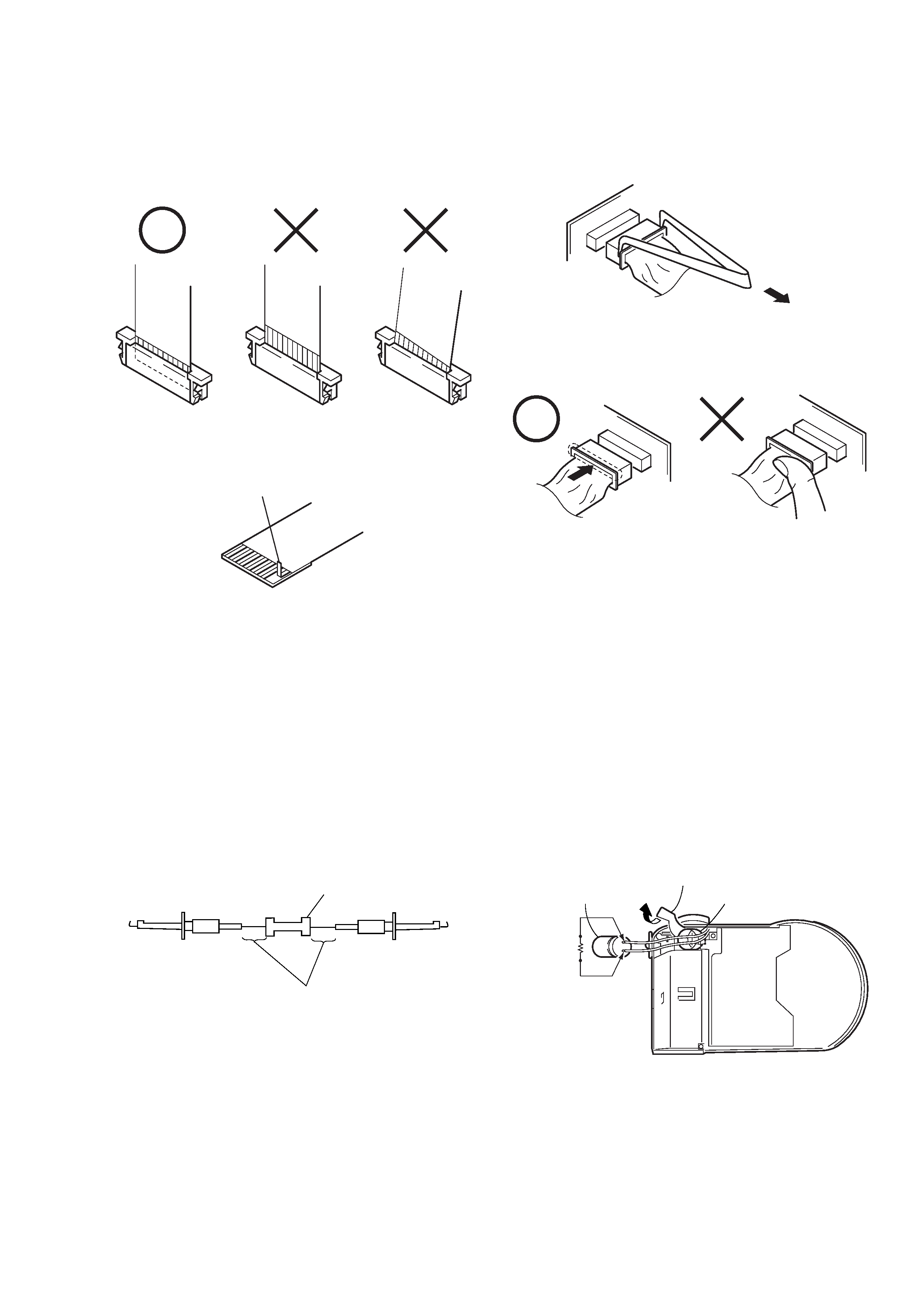
Preparing the Short Jig
To preparing the short jig. a small clip is attached to each end of a
resistor of 1 k
/1 W (1-215-869-11)
Wrap insulating tape fully around the leads of the resistor to prevent
electrical shock.
1 k
/1 W
Wrap insulating tape.
Make sure that the flat cable and flexible board are not cracked of
bent at the terminal.
Do not insert the cable insufficiently nor crookedly.
Cut and remove the part of gilt
which comes off at the point.
(Take care that there are
some pieces of gilt left inside)
When remove a connector, don't pull at wire of connector.
Be in danger of the snapping of a wire.
When installing a connector, don't press down at wire of connector.
Be in danger of the snapping of a wire.
Discharging the Capacitor
Short circuits between the positive and the negative terminals of
charged capacitor with the short jig about 10 seconds.
Capactior
Capactior cap
Short jig
Harness retainer