SERVICE MANUAL
MOBILE DVD SYSTEM
US Model
MV-900SDS
Ver. 1.3 2005.10
9-877-871-04
2005J05-1
© 2005.10
Sony Corporation
e Vehicle Group
Published by Sony Engineering Corporation
SPECIFICATIONS
Copyrights
This product incorporates copyright protection
technology that is protected by method claims
of certain U.S. patents, other intellectual
property rights owned by Macrovision
Corporation, and other rights owners. Use of
this copyright protection technology must be
authorized by Macrovision Corporation, and is
intended for home and other limited viewing
uses only unless otherwise authorized by
Macrovision Corporation. Reverse engineering
or disassembly is prohibited.
· "Memory Stick,"
and "MagicGate
Memory Stick" are trademarks of Sony
Corporation.
· "Memory Stick Duo" and "
"
are trademarks of Sony Corporation.
· "MagicGate" and "
" are
trademarks of Sony Corporation.
· "Memory Stick PRO" and "
"
are trademarks of Sony Corporation.
Manufactured under license from Dolby
Laboratories. "Dolby", "Pro Logic", and the
double-D symbol are trademarks of Dolby
Laboratories.
"DTS," "DTS Digital Surround" and "DTS
Digital Out" are trademarks of Digital Theater
Systems, Inc.
DVD player XVM-R90D
System
Laser
Semiconductor laser
Signal format system
NTSC/PAL
Audio characteristics
Frequency response
20 Hz to 20 kHz
Signal to noise ratio
90 dB (A)
Harmonic distortion
0.05 %
Dynamic range
90 dB
Wow and flutter
below measurable limits
(
±0.001% W PEAK)
General
Outputs
FM output
Audio output
Video output
Optical output
Inputs
Audio input
Video input
DC 12V input
Power requirements
12 V DC
Dimensions
Approx. 285
× 73 × 455 mm
(11 1/4
× 2 7/8 × 18 in)
(w/h/d)
Mass
Approx. 3.5 kg
(7 lb 12 oz)
Operating temperature
0
°C to 45 °C
(32
°F to 113 °F)
Supplied accessories
Card remote commander
RM-X137
Power supply cord (1)
RF modulator cable (1)
Mounting plate (1)
Screws (5)
Tapping screws (8)
Operating Instructions (1)
Monitor
System
Liquid crystal color display
Display
Manual flipdown panel
Drive system
TFT-LCD active matrix
system
Picture size
9 inches wide screen (16:9)
Picture segment
336,960 (w 1,440
× h 234)
dots
Cordless Stereo Headphones
MDR-IF0140
General
Modulation system
Frequency modulation
Carrier frequency
Right 2.8 MHz
Left 2.3 MHz
Frequency response
18
- 22,000 Hz
Power source
DC 1.5 V (size AAA) dry
battery
Mass
Approx. 125 g (4.41 oz)
including battery
Operating temperature
5
°C to 35 °C
(41
°F to 95 °F)
Design and specifications are subject to change
without notice.
MODEL NUMBER LABEL
PRINTED MODEL NAME
DVD PLAYER
MV-900SDS
XVM-R90D
CORDLESS STEREO HEADPHONE
MDR-IF0140
MDR-IF0140
CARD REMOTE COMMANDER
RM-X137
COMPONENT MODEL NAME
MV-900SDS
2
TABLE OF CONTENTS
1.
SERVICING NOTES ................................................ 3
2.
GENERAL
Location of Controls ........................................................
5
3.
DISASSEMBLY
3-1.
Disassembly Flow ...........................................................
9
3-2.
Bracket (Main) ................................................................
9
3-3.
DVD Mechanism Deck Block ......................................... 10
3-4.
MAIN Board .................................................................... 10
3-5.
Rear Cover (Hinge) ......................................................... 11
3-6.
LCD Block ...................................................................... 11
3-7.
LCD Board ...................................................................... 12
3-8.
Liquid Crystal Display Panel (LCD1) ............................. 12
4.
TEST MODE .............................................................. 13
5.
ELECTRICAL ADJUSTMENTS ......................... 14
6.
DIAGRAMS
6-1.
Block Diagram MPEG DECODER Section ............ 19
6-2.
Block Diagram AUDIO Section ............................... 20
6-3.
Block Diagram VIDEO, PANEL Section ................. 21
6-4.
Block Diagram POWER SUPPLY Section .............. 22
6-5.
Printed Wiring Board
MAIN Board (Component Side) ............................... 24
6-6.
Printed Wiring Board
MAIN Board (Conductor Side) ................................. 25
6-7.
Schematic Diagram MAIN Board (1/4) ................... 26
6-8.
Schematic Diagram MAIN Board (2/4) ................... 27
6-9.
Schematic Diagram MAIN Board (3/4) ................... 28
6-10. Schematic Diagram MAIN Board (4/4) ................... 29
6-11. Printed Wiring Board LCD Board (Side A) ............. 30
6-12. Printed Wiring Board LCD Board (Side B) ............. 31
6-13. Schematic Diagram LCD Board (1/4) ...................... 32
6-14. Schematic Diagram LCD Board (2/4) ...................... 33
6-15. Schematic Diagram LCD Board (3/4) ...................... 34
6-16. Schematic Diagram LCD Board (4/4) ...................... 35
6-17. Printed Wiring Board PANEL Section (1/2) ............ 36
6-18. Printed Wiring Boards PANEL Section (2/2) ........... 37
6-19. Schematic Diagram PANEL Section ........................ 38
7.
EXPLODED VIEWS
7-1.
Skirt (Cabinet) Section .................................................... 54
7-2.
Front (Panel) Section ....................................................... 55
7-3.
MAIN Board Section ....................................................... 56
7-4.
Cabinet (Base) Section .................................................... 57
7-5.
LCD Section .................................................................... 58
8.
ELECTRICAL PARTS LIST ................................ 59
Notes on chip component replacement
· Never reuse a disconnected chip component.
· Notice that the minus side of a tantalum capacitor may be
damaged by heat.
Flexible Circuit Board Repairing
· Keep the temperature of the soldering iron around 270 °C
during repairing.
· Do not touch the soldering iron on the same conductor of the
circuit board (within 3 times).
· Be careful not to apply force on the conductor when soldering
or unsoldering.
CAUTION
Use of controls or adjustments or performance of procedures
other than those specified herein may result in hazardous radiation
exposure.
CAUTION
The use of optical instruments with this
product will increase eye hazard.
DANGER
INVISIBLE LASERRADIATIONWHEN OPEN.
AVOID DIRECT EXPOSURE TO BEAM.
This is located on the drive unit's internal
chassis.

3
MV-900SDS
SECTION 1
SERVICING NOTES
The laser diode in the optical pick-up block may suffer electrostatic
break-down because of the potential difference generated by the
charged electrostatic load, etc. on clothing and the human body.
During repair, pay attention to electrostatic break-down and also
use the procedure in the printed matter which is included in the
repair parts.
The flexible board is easily damaged and should be handled with
care.
NOTES ON LASER DIODE EMISSION CHECK
Never look into the laser diode emission from right above when
checking it for adjustment. It is feared that you will lose your sight.
NOTES ON HANDLING THE OPTICAL PICK-UP
BLOCK OR BASE UNIT
UNLEADED SOLDER
Boards requiring use of unleaded solder are printed with the lead-
free mark (LF) indicating the solder contains no lead.
(Caution: Some printed circuit boards may not come printed with
the lead free mark due to their particular size)
: LEAD FREE MARK
Unleaded solder has the following characteristics.
· Unleaded solder melts at a temperature about 40 °C higher
than ordinary solder.
Ordinary soldering irons can be used but the iron tip has to be
applied to the solder joint for a slightly longer time.
Soldering irons using a temperature regulator should be set to
about 350 °C.
Caution: The printed pattern (copper foil) may peel away if
the heated tip is applied for too long, so be careful!
· Strong viscosity
Unleaded solder is more viscou-s (sticky, less prone to flow)
than ordinary solder so use caution not to let solder bridges
occur such as on IC pins, etc.
· Usable with ordinary solder
It is best to use only unleaded solder but unleaded solder may
also be added to ordinary solder.
4
MV-900SDS
About discs this player can
play
This player can play the following discs:
· DVD
· DVD-R/DVD-RW
· Video CD
· Audio CD
· CD-R/CD-RW
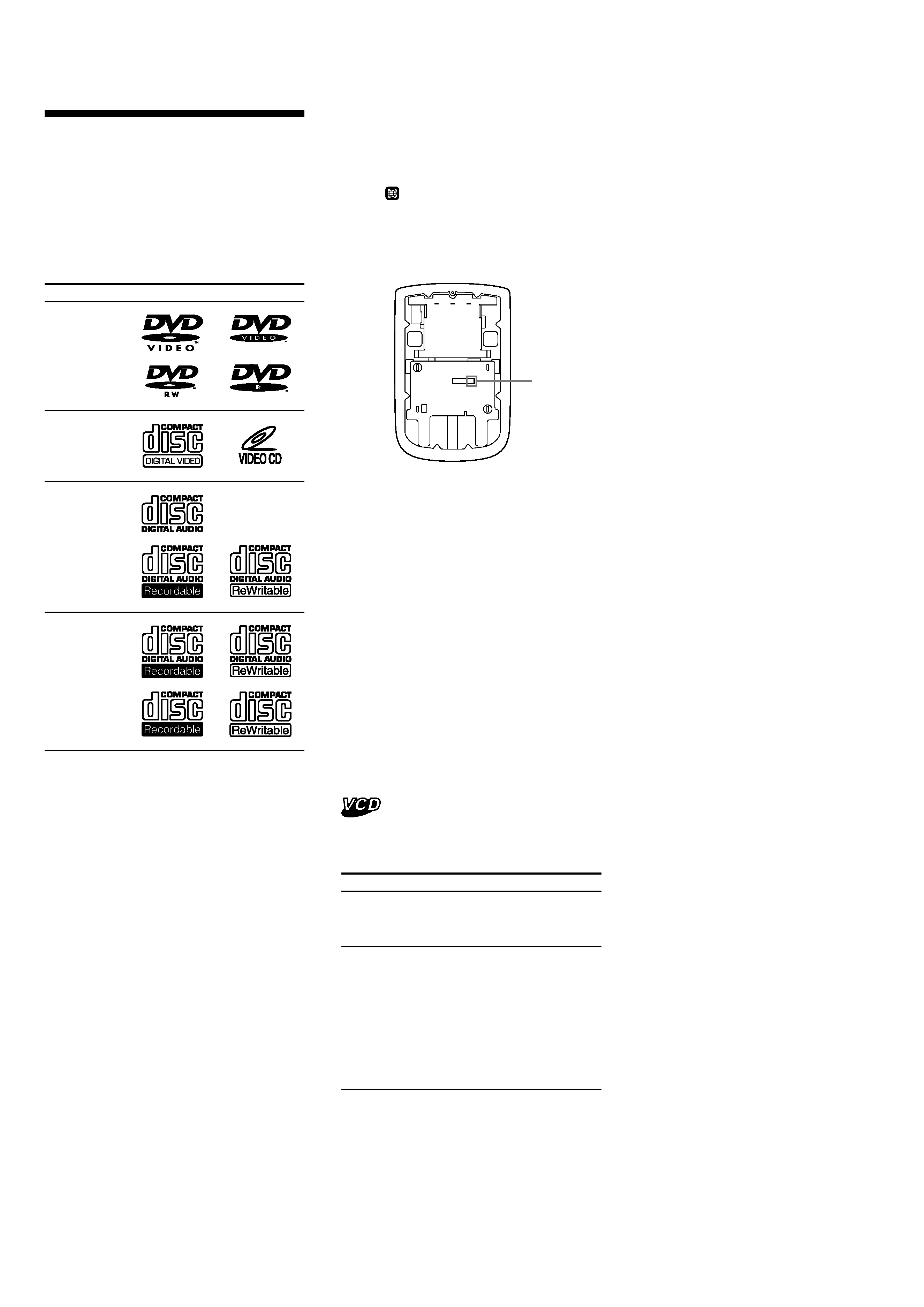
Disc type
Label on the disc
"DVD VIDEO," "DVD-R" and "DVD-RW" are
trademarks.
DVD VIDEOs
Video CDs
Audio CDs
MP3 files/
JPEG files
Notes on CD-Rs (recordable CDs)/
CD-RWs (rewritable CDs)/DVD-Rs
(recordable DVDs)/DVD-RWs
(rewritable DVDs)
· Some CD-Rs/CD-RWs/DVD-Rs/DVD-RWs
(depending on the equipment used for its
recording or the condition of the disc) may
not play on this player.
· You cannot play a CD-R/CD-RW/DVD-R/
DVD-RW that is not finalized*.
· You cannot play a CD-R/CD-RW that is
recorded in Multi Session.
· You can play MP3/JPEG files recorded on
CD-ROMs, CD-Rs, and CD-RWs.
* A process necessary for a recorded CD-R/CD-RW
disc to be played on the audio CD player.
Region code of DVDs this player
can play
This player has a region code printed on the
rear of the player and will only play DVDs that
are labeled with identical region codes. DVDs
labeled ALL will also be played on this player.
If you try to play any other DVD, the message
"REGION ERROR" will appear on the screen.
Depending on the DVD, the region code
indication may not appear even if the DVD is
prohibited by area restrictions.
Region
code
Cautions
· This player CANNOT play these discs.
-- DVD-Audio
-- DVD-RAM
-- DVD-ROM
-- CD-G
-- SVCD
-- CD-I
-- Photo-CD
-- VSD
-- Active-Audio (Data)
-- CD-Extra (Data)
-- Mixed CD (Data)
-- CD-ROM (the data other than the MP3/JPEG
file)
-- DVD-RW recorded in VR mode
· This product incorporates copyright protection
technology that is protected by method claims of
certain U.S. patents and other intellectual
property rights owned by Macrovision
Corporation and other rights owners. Use of this
copyright protection technology must be
authorized by Macrovision Corporation, and is
intended for home and other limited viewing
uses only unless otherwise authorized by
Macrovision Corporation. Reverse engineering or
disassembly is prohibited.
Note on PBC (Playback Control)
This player conforms to Ver. 1.1 and Ver. 2.0 of
Video CD standards. You can enjoy two kinds
of playback according to the disc type.
Disc type
Video CDs without
PBC functions
(Ver. 1.1 discs)
Video CDs with
PBC functions
(Ver. 2.0 discs)
You can
Video playback (moving
pictures) as well as music.
· Interactive software
with menu screens
displayed on the
monitor.
·Video playback
functions.
· High-resolution still
pictures if they are
included on the disc.
5
MV-900SDS
SECTION 2
GENERAL
This section is extracted from
instruction manual.
9
0
qa
qs
qd
qf
qg
qh
1
2
3
4
5
6
7
8
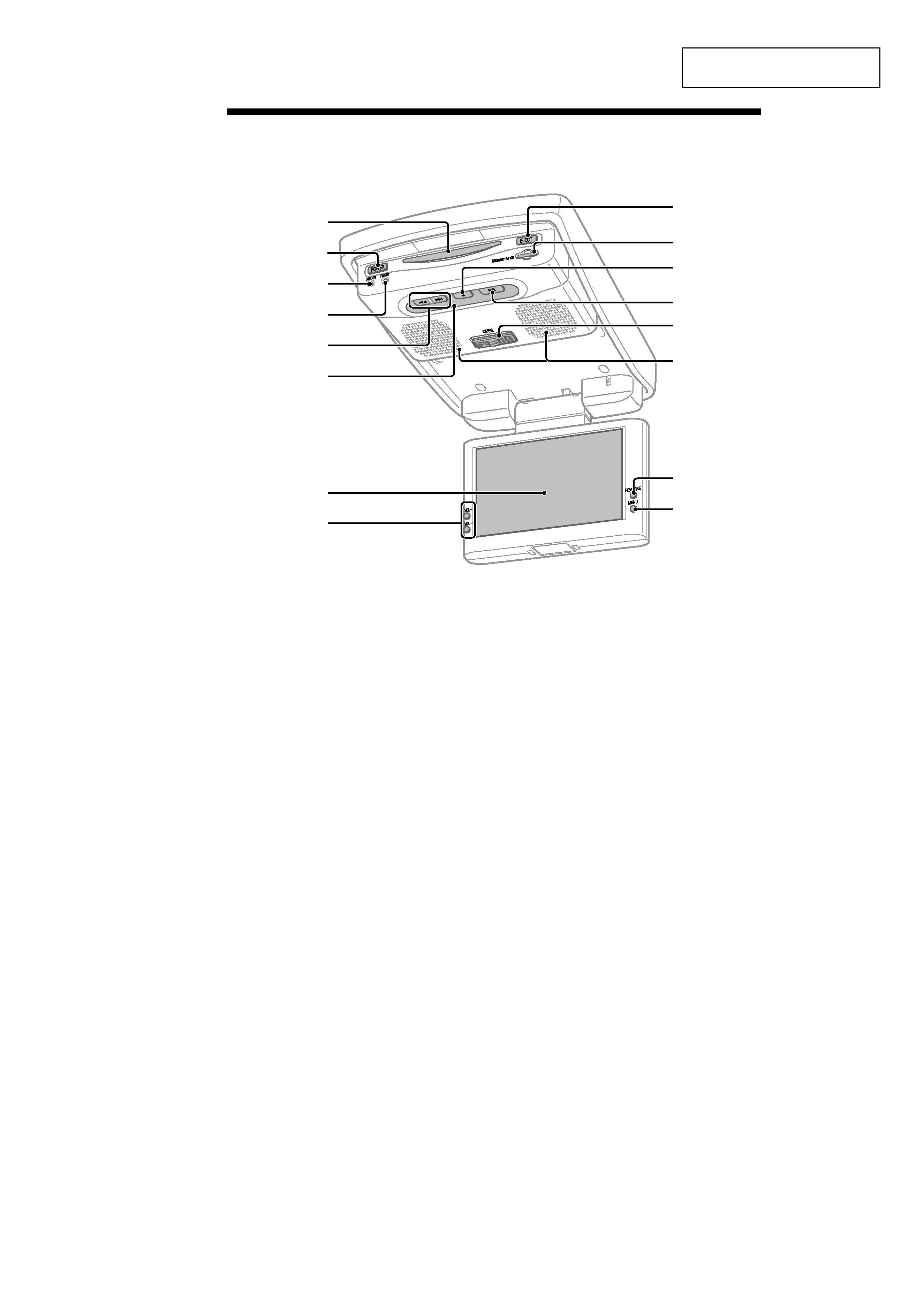
Refer to the pages listed for details.
1 Disc slot
2 POWER (on/off) button
To turn on/off the player.
3 DISC IN light
When a disc is in the player, the DISC IN
light glows orange.
4 RESET button
5 . (previous)/> (next) buttons
6 Receptor for the card remote
commander/Transmitter for the cordless
headphones
7 Monitor
8 VOL +/ buttons
To turn up or down the volume or to select
the item during menu operation.
9 EJECT button
Available to eject a disc from the player
even when the player is turned off.
q; "Memory Stick" slot
qa x (stop) button
qs u (play/pause) button
qd OPEN button
Slide to open the monitor.
qf Speakers (left/right)
qg REVERSE button
To switch images upside down and
reverse the output of the audio channels.
qh MENU button
To make various display settings and FM
transmitter setting.
Note
Even when the player is turned off by pressing
(POWER)
, you can eject a disc from the player,
though you cannot insert a disc.
Location of controls
XVM-R90D