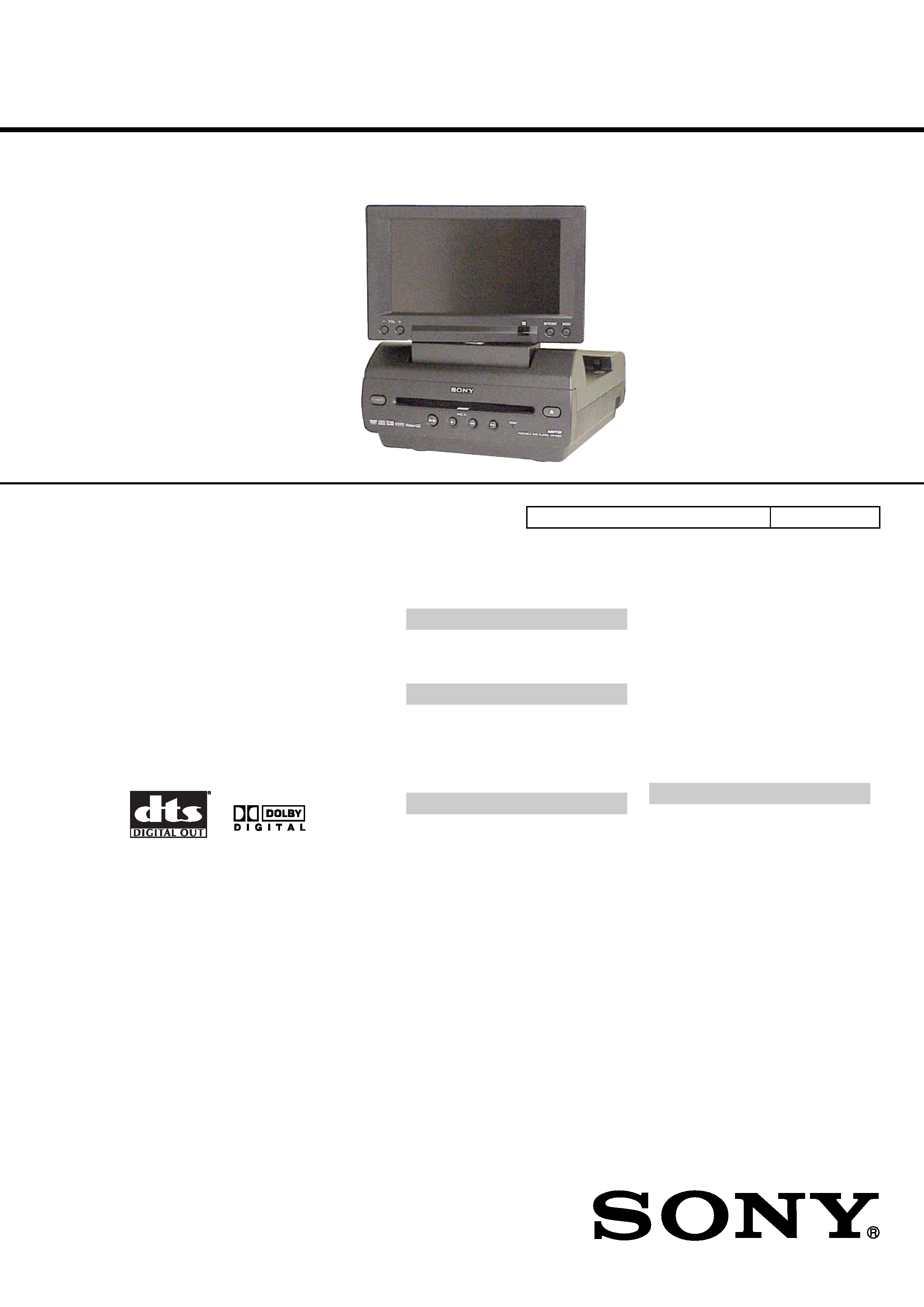
SERVICE MANUAL
PORTABLE DVD PLAYER
US Model
Canadian Model
AEP Model
UK Model
E Model
SPECIFICATIONS
MV-65ST
Ver 1.1 2004.05
9-877-614-02
Sony Corporation
2004E05-1
e Vehicle Company
© 2004.05
Published by Sony Engineering Corporation
Model Name Using Similar Mechanism
NEW
Copyrights
This product incorporates copyright protection
technology that is protected by method claims
of certain U.S. patents, other intellectual
property rights owned by Macrovision
Corporation, and other rights owners. Use of
this copyright protection technology must be
authorized by Macrovision Corporation, and is
intended for home and other limited viewing
uses only unless otherwise authorized by
Macrovision Corporation. Reverse engineering
or disassembly is prohibited.
Manufactured under license from Dolby
Laboratories. "Dolby", "Pro Logic", and the
double-D symbol are trademarks of Dolby
Laboratories. Confidential unpublished works.
Copyright 1998-1999 Dolby Laboratories. All
rights reserved.
"DTS," "DTS Digital Surround" and "DTS
Digital Out" are trademarks of Digital Theater
Systems, Inc.
System
Laser
Semiconductor laser
Signal format system
NTSC/PAL
Audio characteristics
Frequency response
20 Hz to 20 kHz
Signal to noise ratio
90dB (A)
Harmonic distortion
0.03 %
Dynamic range
90dB
Wow and flutter
below measurable limits
(0.001% W PEAK)
Supplied accessories
Mounting straps (4)
AC power adaptor (1)
(including AC power cord
(1))
Power cord for the cigar
lighter socket (1)
Antenna for FM
transmission (1)
(US, Canadian, Mexican only)
Card remote commander
RM-X137 (including
lithium battery (1))
Carrying bag (1)
Operating Instructions (1)
Monitor
System
Liquid crystal color display
Display
Manual flipdown panel
Drive system
TFT-LCD active matrix
system
Picture size
6.5 inches wide screen
(16:9)
Picture segment
280,800 (w 1200
× h 234)
dots
Design and specifications are subject to change
without notice.
General
Outputs
Audio output
Video output
Optical output
Headphones output
Inputs
Audio input
Video input
DC 12V input
Power requirements
12 V DC
Dimensions
Approx. 188
× 99 × 241 mm
(7 1/2
× 4 × 9 1/2 in)
(w/h/d)
Mass
Approx. 2.3 kg
(5 lb 1 oz)
Operating temperature
0 ßC to 45 ßC
(32 ßF to 113 ßF)
2
MV-65ST
Notes on chip component replacement
· Never reuse a disconnected chip component.
· Notice that the minus side of a tantalum capacitor may be dam-
aged by heat.
Flexible Circuit Board Repairing
· Keep the temperature of the soldering iron around 270 °C dur-
ing repairing.
· Do not touch the soldering iron on the same conductor of the
circuit board (within 3 times).
· Be careful not to apply force on the conductor when soldering
or unsoldering.
AEP, UK, E, Mexican models:
SAFETY-RELATED COMPONENT WARNING!!
COMPONENTS IDENTIFIED BY MARK 0 OR DOTTED
LINE WITH MARK 0 ON THE SCHEMATIC DIAGRAMS
AND IN THE PARTS LIST ARE CRITICAL TO SAFE
OPERATION. REPLACE THESE COMPONENTS WITH
SONY PARTS WHOSE PART NUMBERS APPEAR AS
SHOWN IN THIS MANUAL OR IN SUPPLEMENTS PUB-
LISHED BY SONY.
CAUTION
Use of controls or adjustments or performance of procedures
other than those specified herein may result in hazardous ra-
diation exposure.
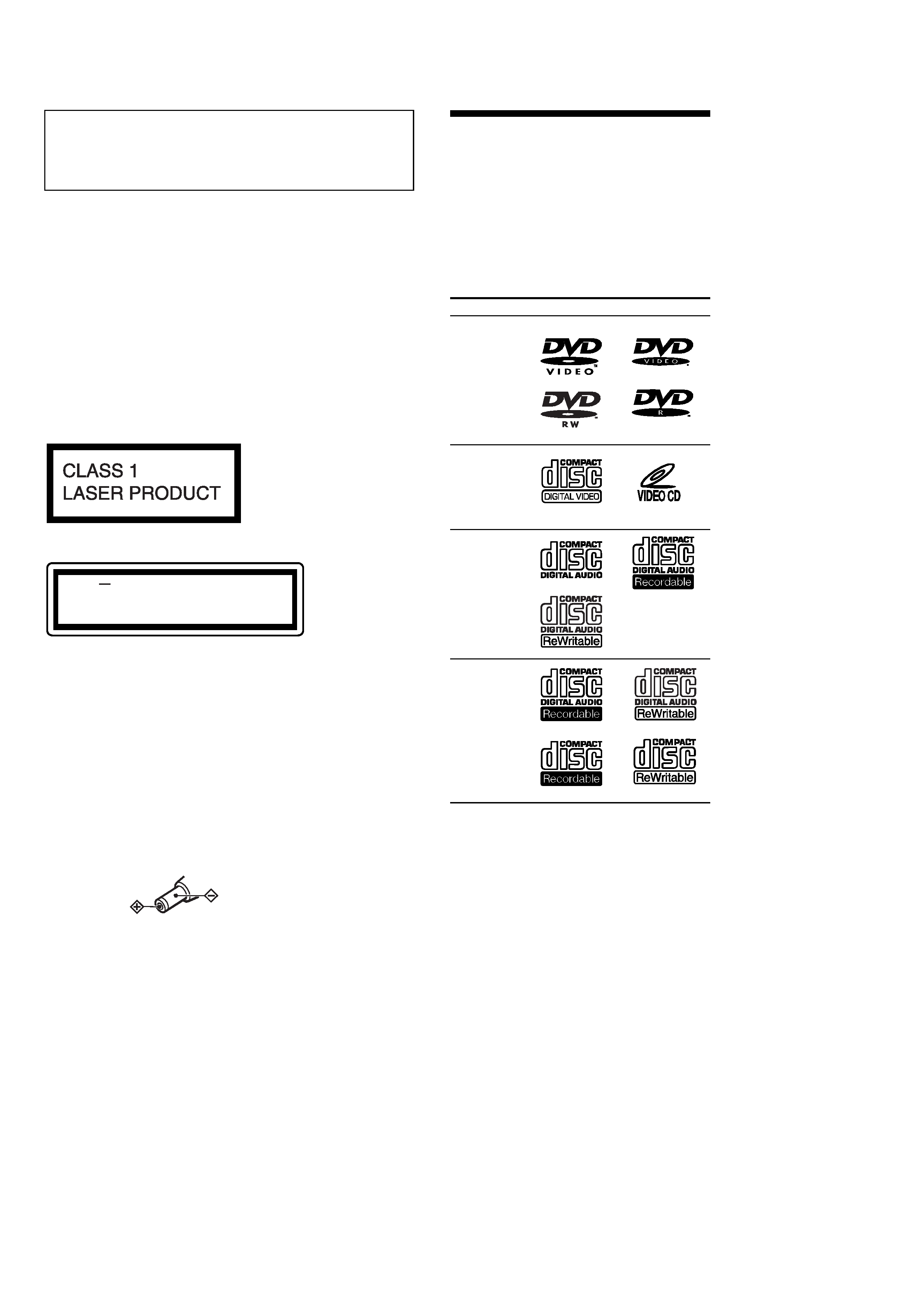
About discs this player can
play
This player can play the following discs:
· DVD
· DVD-R
· DVD-RW
· Video CD
· Audio CD
· CD-R/CD-RW
Disc type
Label on the disc
DVD Videos
Video CDs
Audio CDs
MP3 files/
JPEG files
DVD VIDEO, DVD-R and DVD-RW are
trademarks.
On power sources
· Use house current or car battery (12 V DC).
· For use in your house, use the AC power
adaptor supplied with the player. Do not use
any other AC power adaptor since it may
cause the player to malfunction.
Polarity of
the plug
Notes on CD-Rs (recordable CDs)/
CD-RWs (rewritable CDs)
· Some CD-Rs/CD-RWs (depending on the
equipment used for its recording or the
condition of the disc) may not play on this
player.
· You cannot play a CD-R/CD-RW that is not
finalized*.
· You cannot play a CD-R/CD-RW that is
recorded in Multi Session.
· You can play MP3/JPEG files recorded on
CD-ROMs, CD-Rs, and CD-RWs.
* A process necessary for a recorded CD-R/CD-RW
disc to be played on the audio CD player.
This label is located on the bottom of the
chassis.
CAUTION
INVISIBLE
DO NOT STARE INTO BEAM OR
VIEW DIRECTLY WITH OPTICAL INSTRUMENTS
LASER RADIATION WHEN OPEN
This label is located on the drive unit's internal
chassis.
ATTENTION AU COMPOSANT AYANT RAPPORT
À LA SÉCURITÉ!
LES COMPOSANTS IDENTIFIÉS PAR UNE MARQUE 0
SUR LES DIAGRAMMES SCHÉMATIQUES ET LA LISTE
DES PIÈCES SONT CRITIQUES POUR LA SÉCURITÉ
DE FONCTIONNEMENT. NE REMPLACER CES COM-
POSANTS QUE PAR DES PIÈCES SONY DONT LES
NUMÉROS SONT DONNÉS DANS CE MANUEL OU
DANS LES SUPPLÉMENTS PUBLIÉS PAR SONY.
When replacing the FD-S-TOP-COVER of mechanism deck which
have the "CAUTION LABEL" attached, please be sure to put a
new CAUTION LABEL (3-223-913-11) to the FD-S-TOP-
COVER.
3
MV-65ST
TABLE OF CONTENTS
1.
SERVICING NOTES ............................................... 3
2.
GENERAL
Location of Controls .......................................................
4
3.
DISASSEMBLY
3-1. Disassembly Flow ...........................................................
7
3-2. Base (Monitor) Assy .......................................................
8
3-3. Cabinet (Front) Assy .......................................................
8
3-4. Monitor Assy ...................................................................
9
3-5. Hinge ............................................................................... 10
3-6. MONITOR Board ........................................................... 10
3-7. Liquid Crystal Display Panel (LCD1) ............................ 11
3-8. DVD MD Assy ................................................................ 11
3-9. COMBO Board, Mechanism Deck ................................. 12
3-10. TD-S-Top-Cover ............................................................. 12
3-11. Loading Mechanism Assy ............................................... 13
3-12. Traverse Mechanism Assy .............................................. 13
4.
TEST MODE .............................................................. 14
5.
ELECTRICAL ADJUSTMENTS ......................... 15
6.
DIAGRAMS
6-1. Block Diagram AUDIO Section ............................... 18
6-2. Block Diagram VIDEO, PANEL Section ................ 19
6-3. Block Diagram POWER Section .............................. 20
6-4. Note for Printed Wiring Boards
and Schematic Diagrams ................................................ 21
6-5. Printed Wiring Board
MONITOR Board (Side A) ...................................... 22
6-6. Printed Wiring Board
MONITOR Board (Side B) ...................................... 23
6-7. Schematic Diagram MONITOR Board (1/4) ........... 24
6-8. Schematic Diagram MONITOR Board (2/4) ........... 25
6-9. Schematic Diagram MONITOR Board (3/4) ........... 26
6-10. Schematic Diagram MONITOR Board (4/4) ........... 27
6-11. Printed Wiring Board KEY Board ............................ 28
6-12. Schematic Diagram KEY Board .............................. 29
6-13. Schematic Diagram POWER Section (1/2) .............. 30
6-14. Schematic Diagram POWER Section (2/2) .............. 31
6-15. Printed Wiring Board POWER Board (Side A) ....... 32
6-16. Printed Wiring Board POWER Board (Side B) ....... 33
6-17. Printed Wiring Board AMP Section ......................... 34
7.
EXPLODED VIEWS
7-1. Overall Section ................................................................ 46
7-2. Cabinet (Front) Section ................................................... 47
7-3. Base (Monitor) Section ................................................... 48
7-4. Monitor Section ............................................................... 49
7-5. Cabinet (Lower) Section-1 .............................................. 50
7-6. Cabinet (Lower) Section-2 .............................................. 51
7-7. Mechanism Deck Section-1 ............................................ 52
7-8. Mechanism Deck Section-2 ............................................ 53
7-9. Mechanism Deck Section-3 ............................................ 54
8.
ELECTRICAL PARTS LIST ............................ 55
NOTES ON HANDLING THE OPTICAL PICK-UP
BLOCK OR BASE UNIT
The laser diode in the optical pick-up block may suffer electro-
static break-down because of the potential difference generated
by the charged electrostatic load, etc. on clothing and the human
body.
During repair, pay attention to electrostatic break-down and also
use the procedure in the printed matter which is included in the
repair parts.
The flexible board is easily damaged and should be handled with
care.
NOTES ON LASER DIODE EMISSION CHECK
Never look into the laser diode emission from right above when
checking it for adjustment. It is feared that you will lose your sight.
UNLEADED SOLDER
Boards requiring use of unleaded solder are printed with the lead-
free mark (LF) indicating the solder contains no lead.
(Caution: Some printed circuit boards may not come printed with
the lead free mark due to their particular size)
: LEAD FREE MARK
Unleaded solder has the following characteristics.
· Unleaded solder melts at a temperature about 40 °C higher than
ordinary solder.
Ordinary soldering irons can be used but the iron tip has to be
applied to the solder joint for a slightly longer time.
Soldering irons using a temperature regulator should be set to
about 350
°C.
Caution: The printed pattern (copper foil) may peel away if the
heated tip is applied for too long, so be careful!
· Strong viscosity
Unleaded solder is more viscou-s (sticky, less prone to flow)
than ordinary solder so use caution not to let solder bridges oc-
cur such as on IC pins, etc.
· Usable with ordinary solder
It is best to use only unleaded solder but unleaded solder may
also be added to ordinary solder.
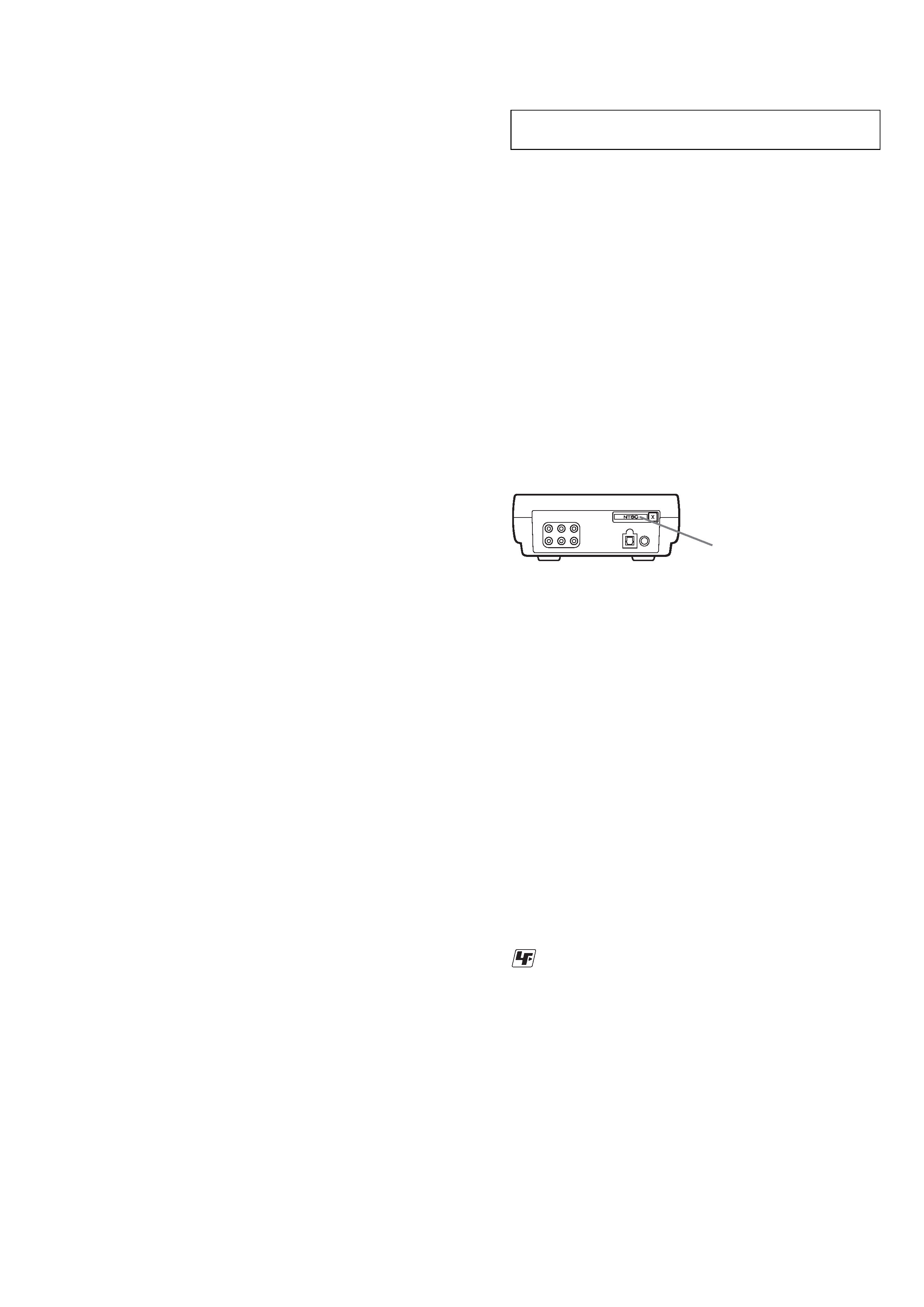
For E model NTSC type and PAL type.
The type of an NTSC system and the type of a PAL system exist in
E model.
Please refer to the following figure about how to recognize.
NTSC: NTSC TYPE
PAL: PAL TYPE
BACK VIEW
SECTION 1
SERVICING NOTES
Ver 1.1
4
MV-65ST
SECTION 2
GENERAL
This section is extracted from
instruction manual.
MV-65ST
DISC IN
RESET
6
7
8
9
0
qa
qd
qs
qf
qg
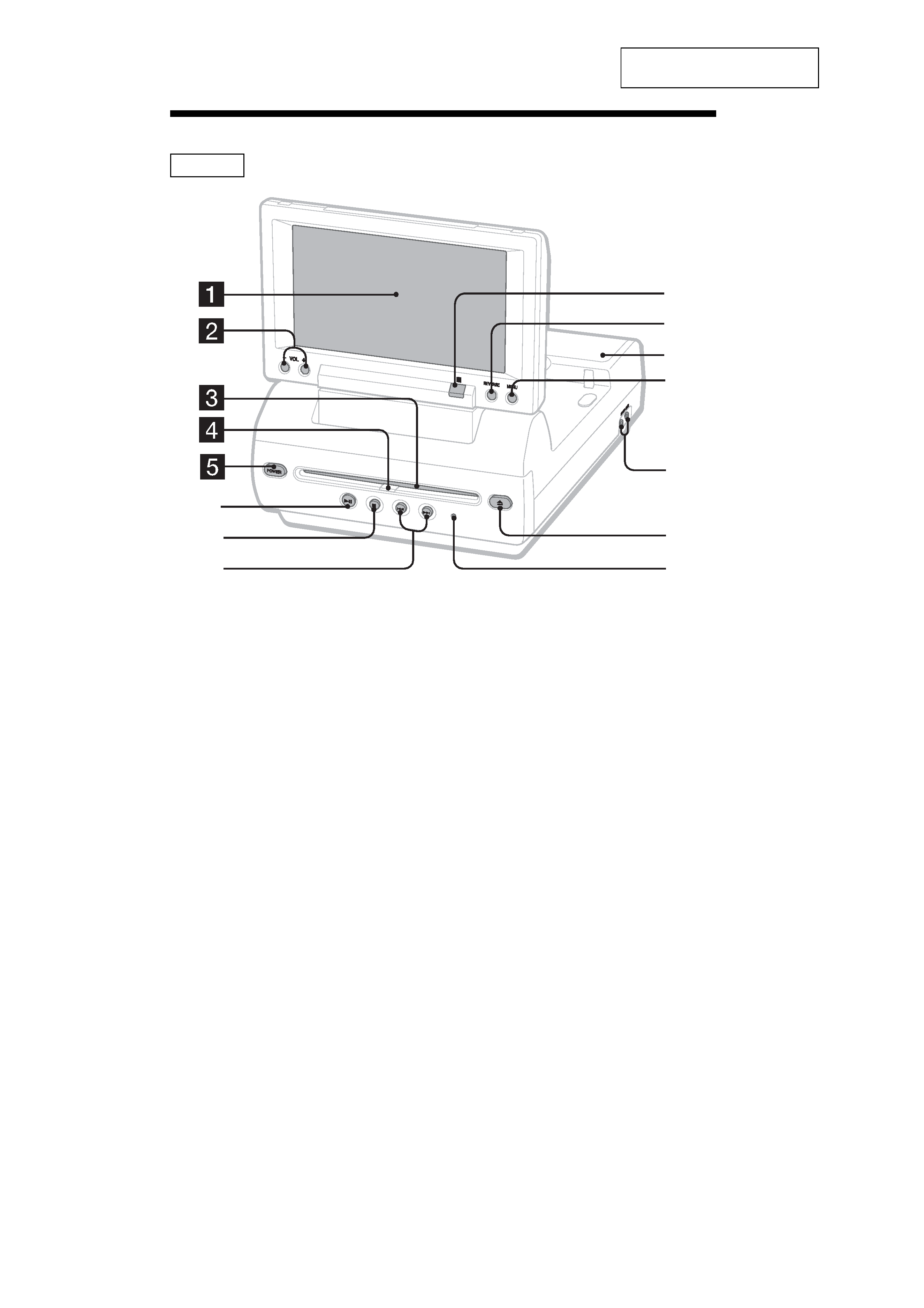
Refer to the pages listed for details.
1 Monitor
2 VOL
-/+ buttons
To turn up or down the volume or to select
the item during menu operation.
3 Disc slot
4 DISC IN light
When a disc is in the player, the DISC IN
light glows orange.
5 POWER (on/off) button
To turn on/off the player.
6 u (play/pause) button
7 x (stop) button
8 . (previous)/> (next) buttons
9 Receptor for the card remote
commander
q; Reverse button
To switch images upside down and
reverse the output of the audio channels.
qa Speakers (left/right)
qs MENU button
To make various display settings and FM
transmitter setting.
qd HEADPHONES jacks
To connect the headphones. 2 sets of
headphones can be connected.
qf Z (eject) button
Available to eject a disc from the player
even when the player is turned off.
qg RESET button
Note
Even when the player is turned off by pressing
(POWER)
, you can eject a disc from the player,
though you cannot insert a disc.
Location of controls
5
MV-65ST
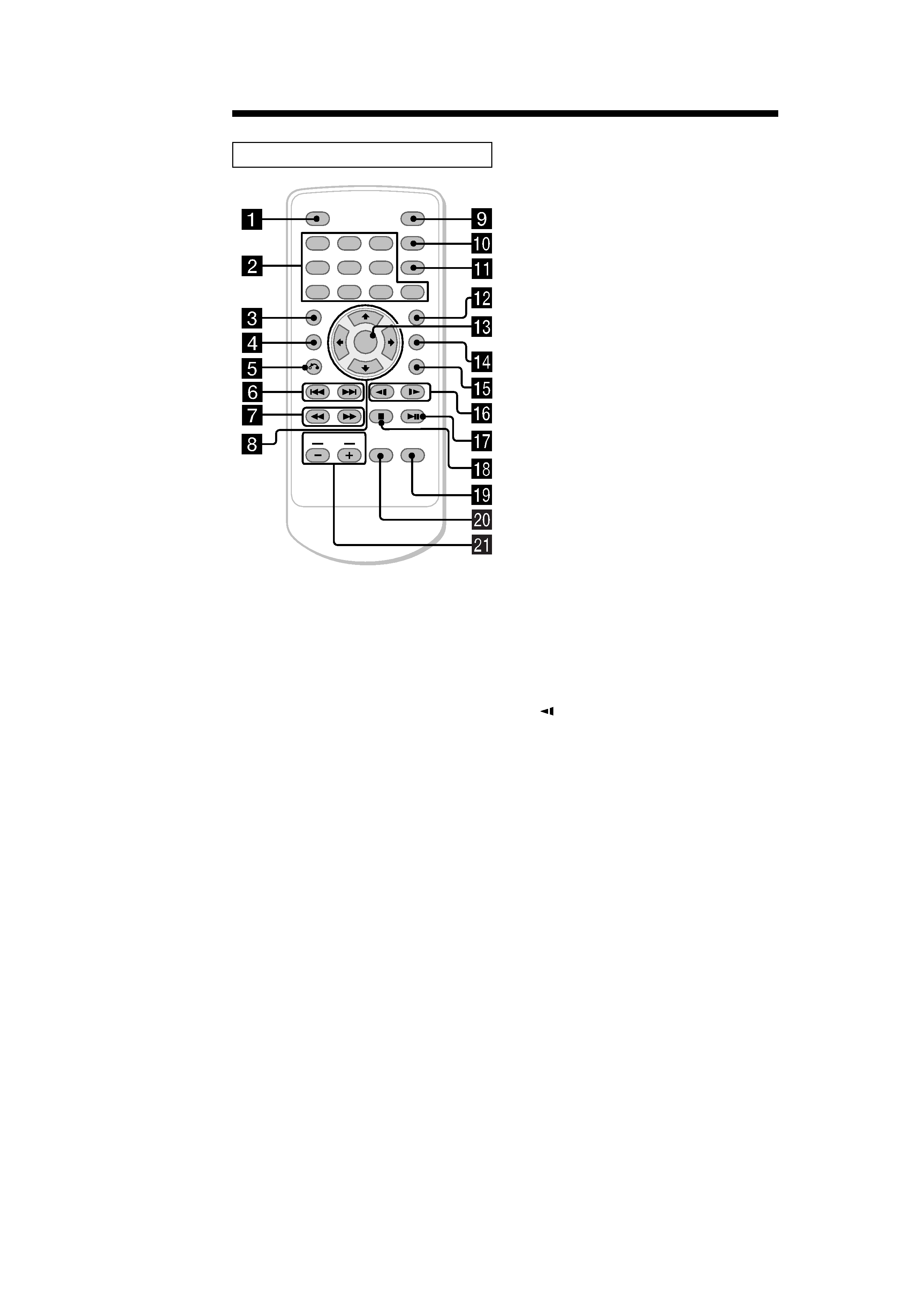
Card remote commander RM-X137
ENTER
SEARCH
POWER
DISPLAY
CLEAR
SETUP
AUDIO
ANGLE
SUBTITLE
MENU
TOP MENU
INPUT
12
3
45
6
7
890
VOL
Refer to the pages listed for details.
1 DISPLAY button
To display the time information of the disc.
2 Number buttons (0 to 9)
3 TOP MENU button
To display the top menu of a recorded
DVD.
4 MENU button
To display the recorded DVD menu, or to
turn on/off the PBC (Playback control)
menu of a Video CD.
5 O (return) button
6 ./> (previous/next) buttons
7 m (fast reverse)/
M
(fast forward) buttons
8 M/,/m/< buttons
9 POWER (on/off) button
To turn on/off the player.
q; SEARCH button
To specify a desired point on a disc by
chapter, title, or track.
qa CLEAR button
qs SUBTITLE button
To change the subtitle language while
playing a DVD.
qd ENTER button
To enter a setting.
qf ANGLE button
To select the multiple angles of view while
playing a DVD.
qg AUDIO button
To change the audio output/audio
language.
qh
(slow reverse)/y (slow forward)
buttons
qj u (play/pause) button
qk x (stop) button
ql SETUP buttons
Used to perform menu operations.
w; INPUT button
To select the input source.
wa VOL (
-/+) buttons
To turn up or down the volume.
The corresponding buttons of the card
remote commander control the same
functions as those on the player.
Instructions in this manual describe how to use
the player by mainly using the card remote
commander.
Tip
Refer to "Replacing the lithium battery of the card
remote commander" for details on how to replace
the battery.