DIGITAL MECHANISM DECK
MICRO MV MECHANICAL ADJUSTMENT MANUAL 1
V MECHANISM
Please use this manual with the service manual of the respective models.
Ver 1.1 2002. 07

-- 2 --
TABLE OF CONTENTS
1.
Preparing for Check, Adjustment and Parts
Replacement of Mechanism Block
1-1.
Service Jigs and Tools ························································ 3
1-2.
Simple MSW Jig Operating Procedure ······························ 5
1-2-1. Overview ············································································ 5
1-2-2. Connection Method ···························································· 5
1-2-3. Operation ············································································ 6
2.
Periodic Inspection and Maintenance
2-1.
Drum Assy Cleaning ·························································· 7
2-2.
Tape Path System Cleaning ················································ 7
2-3.
Periodic Inspection List ······················································ 8
3.
Before starting the Replacement,
Check and Adjustment Work
3-1.
Handling Drum Assy
(on Mechanism Deck in which Drum Assy is installed) ···· 9
3-2.
Adjusting the Phase ···························································· 9
4.
How to Confirm Mechanism Block
and to Replace Parts
4-1.
Flow Chart of Parts Replacement ····································· 10
4-2.
M Cover (MOLD), Drum Assy ········································ 11
4-3.
Drum Base Block Assy ····················································· 12
4-4.
Cassette Compartment Assy ············································· 13
4-5.
LED Base Assy ································································· 14
4-6.
Gooseneck Gear Assy, T-reel Table Assy ························· 15
4-7.
Pinch Arm Block Assy, T-Brake Spring ··························· 16
4-8.
T-Soft, S-Brake Block Assy ············································· 17
4-9.
Regulator Arm Block Assy, S-reel Table Assy ················· 18
4-10. MIC (DH-037) Board, Sensor Holder S, LS Support ······ 19
4-11. LS Chassis Block Assy ····················································· 20
4-12. Tape (Top/End) Sensor, Reel (S/T) Sensor,
REC Proof Switch ···························································· 22
4-13. Rail, Coaster (S/T) Block Assy, GL (S/T) Block Assy ···· 23
4-14. EJ Lever, EJ Lever Holder ················································ 25
4-15. Conversion Gear, Relay Gear ··········································· 26
4-16. Capstan Motor ·································································· 27
4-17. RVS Brake Arm ································································ 28
4-18. Cam Gear Assy, Mode Gear Assy ···································· 29
4-19. Cam Base, Position Arm, Motor Assy (Loading),
FP-228 Flexible Board, Motor Holder ····························· 30
4-20. No. 1 Gear, No. 2 Gear, Cam Gear Assy ·························· 32
4-21. Mode Slider, Chassis Sub-Block Assy ····························· 33
5.
Adjustment
5-1.
Tension Regulator FWD Position Adjustment ················· 34
5-2.
FWD BT (Back Tension) Adjustment ······························ 35
5-3.
Tape Path Adjustment ······················································· 36
3-1.
Adjustment preparation ···················································· 36
3-2.
TG2/TG5 Guide Coarse Adjustment ································ 37
3-3.
TG1/TG6 Guide Coarse Adjustment ································ 38
3-4.
TG2 Guide Adjustment ···················································· 38
3-5.
TG5 Guide Adjustment ···················································· 39
3-6.
TG1 Guide Adjustment ···················································· 39
3-7.
TG6 Guide Adjustment ···················································· 40
3-8.
Check upon Completion of Adjustment ··························· 41
6.
Exploded View
6-1.
OVERALL MECHANISM DECK SECTION (V100) ···· 42
6-2.
LS CHASSIS SECTION ·················································· 43
6-3.
MECHANISM CHASSIS SECTION ······························ 44
7.
Schematic Diagram ················································· 45
8.
Printed Wiring Board ·············································· 46

-- 3 --
1-1. Service Jigs and Tools
Ref. No.
J-1
J-2
J-3
J-4
J-5
J-6
J-7
J-8
J-9
J-10
J-11
J-12
J-13
J-14
Name
Wiping cloth
Super-fine applicator
(made by Nippon Applicator (P752D))
FLOIL grease (SG-941)
Mirror (small oval type)
Torque screwdriver
Adjustable wrist strap
Adjustment remote commander (RM-95)
Tension regulator FWD position adjustment jig
(V mechanism)
Tracking tape
FWD back tension measurement tool
Tape path adjustment screwdriver
Simple MSW jig
Connecting harness (V mechanism)
Reel weight
Part code
7-741-900-53
--
7-662-001-39
J-6080-840-A
J-9049-330-A
J-2501-162-A
J-6082-053-B
J-6082-540-A
8-967-998-01
J-6082-543-A
J-6082-541-A
J-6082-542-A
J-6082-544-A
J-6082-545-A
Jig inscription
GD-2038
Used for
For tape path
Countermeasure for static electricity of
drum assy
Partially modified part; Note 1
For tension regulator FWD position
adjustment
For tape path adjustment
For FWD BT (back tension) adjustment
For tape guide adjustment
V mechanism mode transition
operations
For FWD BT (back tension) adjustment
Other equipment required: Oscilloscope
Note 1: If the microprocessor in the adjustment remote commander is not
the new one (UPD7503G-C56-12), the pages cannot be switched.
In this case, replace it with the new microprocessor (UPD7503G-
C56-12; 8-759-148-35).
1. Preparing for Check, Adjustment and Parts Replacement of Mechanism Block
Before starting check, adjustment and parts replacement of mechanism block
1)
For the method of "how to remove the mechanism block" when performing check, adjustment and parts replacement of mechanism
block, refer to "How to Remove Mechanism Block" described in the mechanical adjustment manual of each model.
2)
When performing check, adjustment and parts replacement of mechanism block, use the Simple MSW jig in order to facilitate the above
operations at all times. For the selection of each [
] mode that is specified in this manual, refer to "Section 1-2. Simple MSW Jig
Operating Procedure" of this manual.
3)
Disassembling, re-assembling and adjustment of the mechanism block are performed using the [ULE] mode unless otherwise specified.
-- 4 --
J-1
J-2
J-3
J-4
J-5
J-6
J-7
J-8
J-9
J-10
J-11
J-12
J-13
J-14
Fig. 1-1
-- 5 --
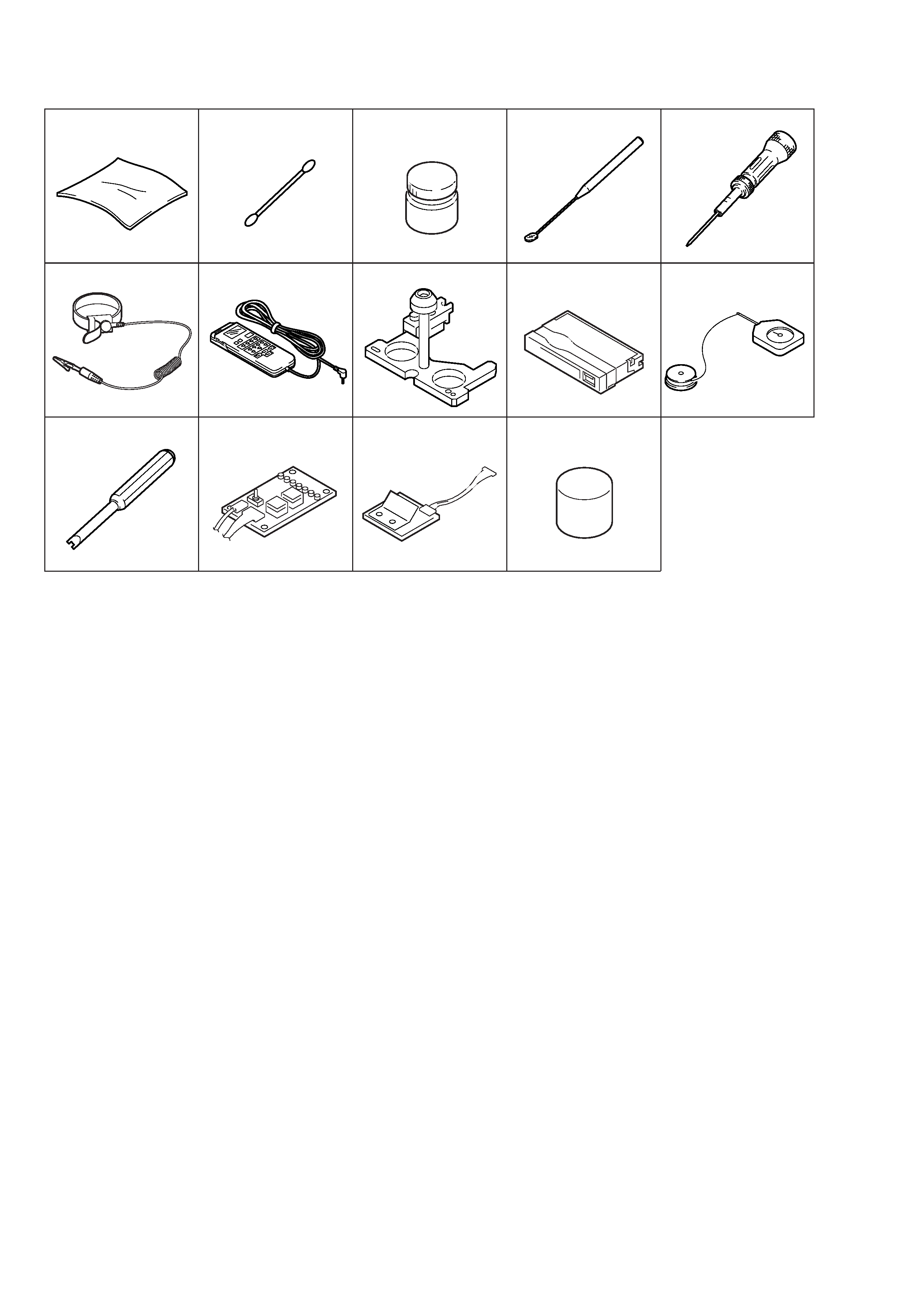
1-2. Simple MSW Jig Operating Procedure
1-2-1. Overview
This jig is the mechanism drive tool that assists maintenance wok
of the V mechanism deck.
Identifying the Main Parts
Fig. 1-2
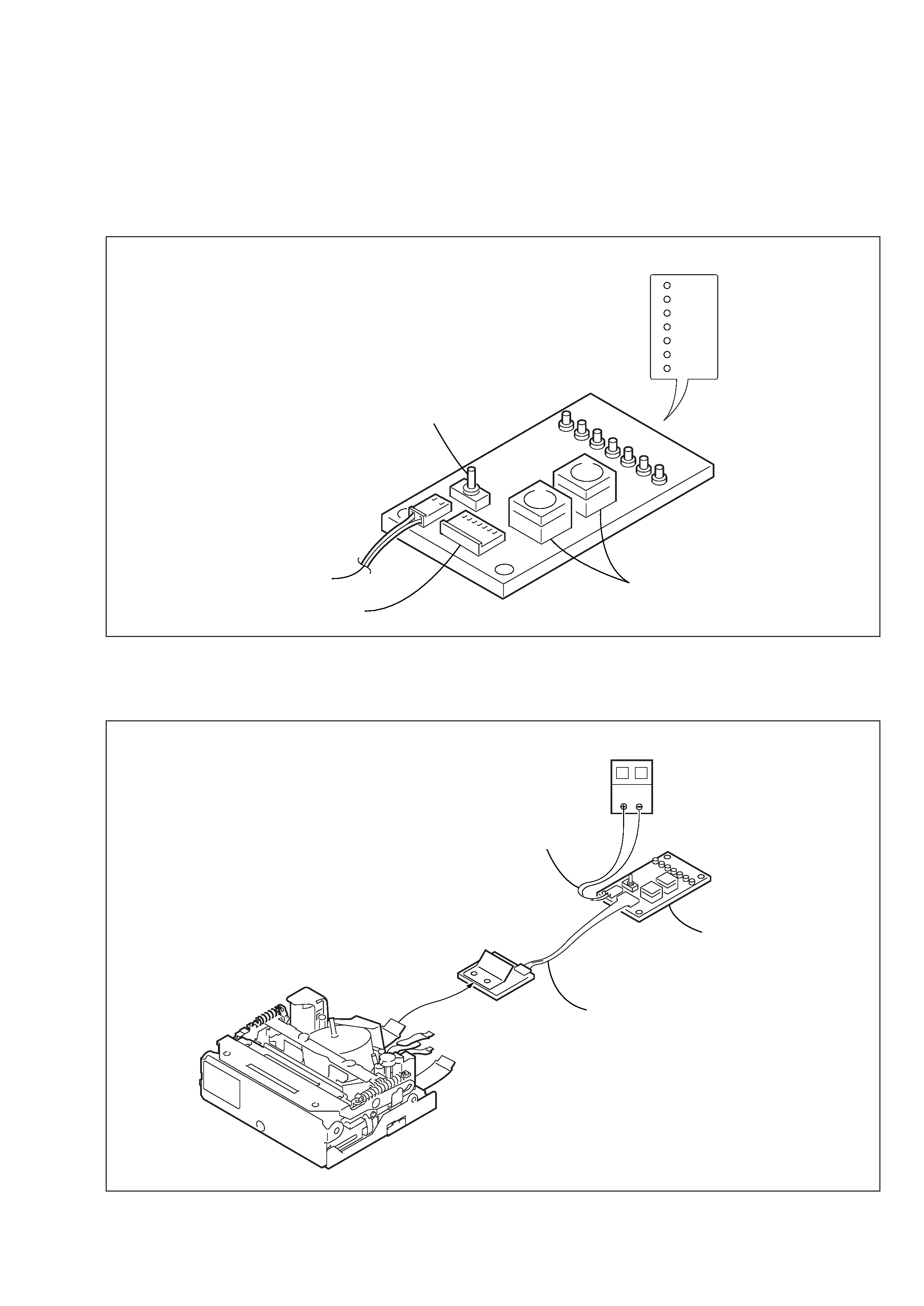
Fig. 1-3
1-2-2. Connection Method
Mode position selector switch
Mode position display switch
Connector for the connecting harness
DC power
POWER swtich
EJECT
ULE
SR
GL
STOP
RP
BLANK
RP
BLANK
STOP
GL
SR
ULE
EJECT
POWER
V-mechanism deck
Clip
DC power (+5 V)
Power cord
Simple MSW jig
Ref. No. J-12
Connecting harness
Ref. No. J-13