MHC-DP1000D
US Model
Canadian Model
AEP Model
UK Model
E Model
Australian Model
SERVICE MANUAL
MINI Hi-Fi COMPONENT SYSTEM
Sony Corporation
Home Audio Company
Sinagawa Tec Service Manual Production Group
Ver 1.0 2001. 09
9-873-315-01
2001I0200-1
© 2001.9
COMPONENT MODEL NAME
· MHC-DP1000D is composed of following models.
As for the service manual, it is issued for each component model,
then, please refer to them.
DVD DECK
RECEIVER SYSTEM
SPEAKER
SYSTEM
PARTS LIST
Part No.
Description
Remark
ACCESSORIES
************
1-476-445-11
REMOTE COMMANDER (RM-SD270)
1-501-374-11
ANTENNA, LOOP
1-501-594-11
ANTENNA (FM)(AEP,UK)
1-501-659-71
ANTENNA (FM)(EXCEPT AEP,UK)
1-558-848-11
CORD, SPEAKER (SS-DP1000D/DP1000DW)(3m)
1-769-433-11
CORD, SPEAKER (SS-RS270) (10m)
1-769-433-41
CORD, SPEAKER (SS-CT270) (2.5m)
1-782-981-21
CORD, CONNECTION
4-210-254-0
1
CUSHION (FOOT)
4-232-032-01
COVER, BATTERY (FOR RM-SD270)
4-232-734-11
MANUAL, INSTRUCTION (SS-DP1000DW)
(ENGLISH,FRENCH,GERMAN,SPANISH,DUTCH,SWEDISH,
ITALIAN,PORTUGUESE,TURKISH,POLISH,HUNGARIAN,
GREEK,FINNISH,DANISH,CZECH,RUSSIAN)
4-232-961-01
FOOT (SS-RC270)
4-236-762-11
MANUAL, INSTRUCTION (ENGLISH)
(US,CND,UK,AUS,E91,EA)
4-236-762-21
MANUAL, INSTRUCTION (FRENCH)(CND,EA)
4-236-762-31
MANUAL, INSTRUCTION (SPANISH)(MX)
4-236-762-41
MANUAL, INSTRUCTION (ENGLISH,FRENCH,SPANISH)
(AEP,E)
4-236-762-51
MANUAL, INSTRUCTION (GERMAN,DUTCH,ITALIAN)(AEP)
4-236-762-61
MANUAL, INSTRUCTION (SWEDISH,POLISH)(AEP)
4-236-762-71
MANUAL, INSTRUCTION (ARABIC)(EA)
4-236-762-81
MANUAL, INSTRUCTION (TRADITIONAL CHINESE)(SP,MY)
4-236-763-11
MANUAL, INSTRUCTION (DANISH,FINNISH)(AEP)
4-236-763-21
MANUAL, INSTRUCTION (PORTUGUESE)(AEP)
4-236-763-31
MANUAL, INSTRUCTION (GREEK)(AEP)
4-236-763-41
MANUAL, INSTRUCTION (HUNGARIAN,CZECH)(AEP)
4-236-763-51
MANUAL, INSTRUCTION (TURKISH)(AEP)
4-236-763-61
MANUAL, INSTRUCTION (SLOVAK)(AEP)
4-236-764-11
MANUAL, INSTRUCTION (ENGLISH,THAI)(TH)
HCD-DP1000D
SS-DP1000DW (US,CND,AEP,UK)
SS-DP1000D
(EXCEPT US,CND,AEP,UK)
· Abbreviation
CND: Canadian model
SP
: Singapore model
MY : Malaysia model
EA : Saudi Arabia model
SPECIFICATIONS
FRONT SPEAKER
SS-RC270
REAR SPEAKER
CENTER SPEAKER
SS-RS270
SS-CT270
General
Power requirements
North American model:
120 V AC, 60 Hz
European model:
230 V AC, 50/60 Hz
Australian model:
230 240 V AC,
50/60 Hz
Mexican model:
120 V AC, 60 Hz
Thailand model:
220 V AC, 50/60 Hz
Indian, Pakistani, Moroccan and Tunisian models:
220 V AC, 50/60 Hz
Other models:
120 V, 220 V or
230 240 V AC,
50/60 Hz
Adjustable with voltage
selector
Power consumption
U.S.A. model:
205 watts
Canadian model:
205 watts
European model:
190 watts
0.5 watts (at the Power
Saving Mode)
Other models:
225 watts
Dimensions (w/h/d)
Approx. 280 x 360 x 365mm
Mass
North American and European models:
Approx. 11.0 kg
Other models:
12.0 kg
Supplied accessories:
AM loop antenna (1)
FM lead antenna (1)
Remote commander (1)
Batteries (2)
Video cable (1)
Front speaker pads (8)
Center and rear speaker
pads (12)
Design and specifications are subject to change without notice.
E91 : 220V AC area model
AUS : Australian model
MX : Mexican model
TH : Thai model

MHC-DP1000D
REVISION HISTORY
Clicking the version allows you to jump to the revised page.
Also, clicking the version at the upper right on the revised page allows you to jump to the next revised
page.
Ver.
Date
Description of Revision
1.0
2001.09
New
HCD-DP1000D
US Model
Canadian Model
AEP Model
UK Model
E Model
Australian Model
MINI HI-FI COMPONENT SYSTEM
-- Continued on next page --
SPECIFICATIONS
· HCD-DP1000D is the tuner, deck,
DVD and amplifier section in MHC-
DP1000D.
Ver 1.8 2003.12
9-873-314-09
2003L02-1
© 2003.12
Sony Corporation
Home Audio Company
Published by Sony Engineering Corporation
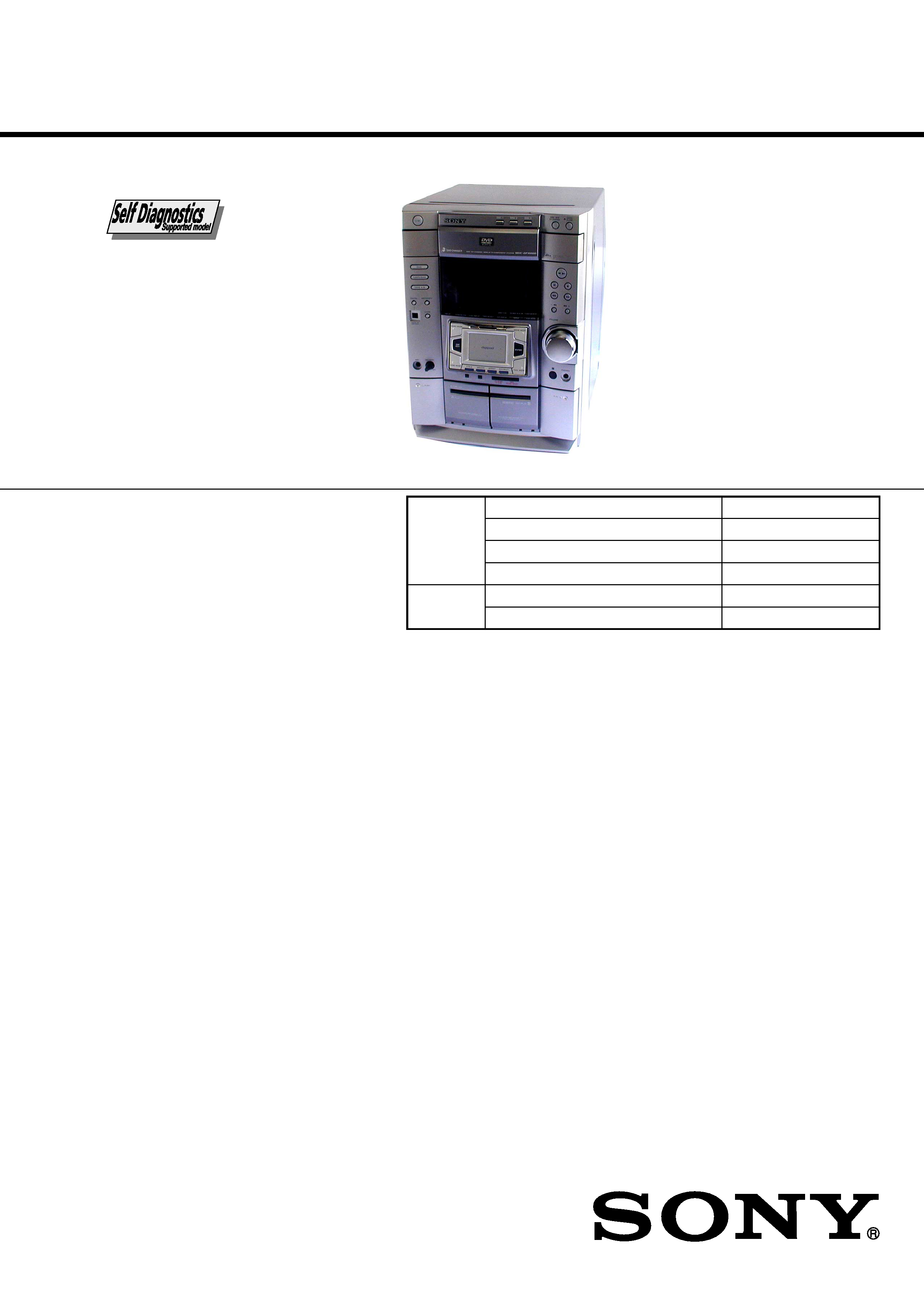
PHOTO :E model
Model Name Using Similar Mechanism
NEW
DVD
DVD Mechanism Type
CDM58D-DVBU9
Section
Base Unit Name
DVBU9
Optical Pick-up Name
KHM-240AAA/CLNP
Tape deck
Model Name Using Similar Mechanism
HCD-DP800AV
Section
Tape Transport Mechanism Type
TCM-230AWR41/MWR41
SERVICE MANUAL
AUDIO POWER SPECIFICATIONS:
(USA model only)
POWER OUTPUT AND TOTAL
HARMONIC DISTORTION
with 8 ohm loads both channels driven, from
120 Hz 10 kHz; rates 100 watts per channel
minimum RMS power, with no more than 10%
total harmonic distortion from 250 milliwatts to
rated output.
Continuous RMS power output
Center speaker:
30 watts
Rear speakers:
30 + 30 watts
(8 ohms at 1 kHz, 10% THD)
Amplifier section
Canadian model:
Continuous RMS power output (reference)
Front speaker:
100 + 100 watts
Center speaker:
30 watts
Rear speakers:
30 + 30 watts
(8 ohms at 1 kHz, 10% THD)
Total harmonic distortion less than 0.07%
(8 ohms at 1 kHz, 70 W)
European model:
DIN power output (rated) 60 + 60 watts
(8 ohms at 1 kHz, DIN)
Continuous RMS power output (reference)
Front speaker:
80 + 80 watts
Center speaker:
30 watts
Rear speakers:
30 + 30 watts
(8 ohms at 1 kHz, 10% THD)
Music power output (reference)
Front speaker:
150 + 150 watts
Center speaker:
60 watts
Rear speakers:
60 + 60 watts
(8 ohms at 1 kHz, 10% THD)
Other models:
The following measured at AC 120, 220, 240 V,
50/60 Hz
DIN power output (rated) 90 + 90 watts
(8 ohms at 1 kHz, DIN)
Continuous RMS power output (reference)
Front speaker:
120 + 120 watts
Center speaker:
40 watts
Rear speakers:
40 + 40 watts
(8 ohms at 1 kHz, 10% THD)
Inputs
GAME IN:
voltage 250 mV,
(phono jacks)
impedance 47 kilohms
MD (VIDEO) IN:
voltage 450 mV/250 mV,
(phono jacks)
impedance 47 kilohms
OPTICAL IN:
(Square optical connector jacks, front panel)
wavelength
----
MIC:
sensitivity 1 mV,
(Except for North
impedance 10 kilohms
American and
European models)
(phone jack)

2
HCD-DP1000D
NOTES ON HANDLING THE OPTICAL PICK-UP
BLOCK OR BASE UNIT
The laser diode in the optical pick-up block may suffer electrostatic
break-down because of the potential difference generated by the
charged electrostatic load, etc. on clothing and the human body.
During repair, pay attention to electrostatic break-down and also
use the procedure in the printed matter which is included in the
repair parts.
The flexible board is easily damaged and should be handled with
care.
NOTES ON LASER DIODE EMISSION CHECK
The laser beam on this model is concentrated so as to be focused on
the disc reflective surface by the objective lens in the optical pick-
up block. Therefore, when checking the laser diode emission,
observe from more than 30 cm away from the objective lens.
SAFETY-RELATED COMPONENT WARNING!!
COMPONENTS IDENTIFIED BY MARK 0 OR DOTTED LINE WITH
MARK 0 ON THE SCHEMATIC DIAGRAMS AND IN THE PARTS
LIST ARE CRITICAL TO SAFE OPERATION. REPLACE THESE
COMPONENTS WITH SONY PARTS WHOSE PART NUMBERS
APPEAR AS SHOWN IN THIS MANUAL OR IN SUPPLEMENTS
PUBLISHED BY SONY.
ATTENTION AU COMPOSANT AYANT RAPPORT
À LA SÉCURITÉ!
LES COMPOSANTS IDENTIFÉS PAR UNE MARQUE 0 SUR LES
DIAGRAMMES SCHÉMATIQUES ET LA LISTE DES PIÈCES SONT
CRITIQUES POUR LA SÉCURITÉ DE FONCTIONNEMENT. NE
REMPLACER CES COMPOSANTS QUE PAR DES PIÈSES SONY
DONT LES NUMÉROS SONT DONNÉS DANS CE MANUEL OU
DANS LES SUPPÉMENTS PUBLIÉS PAR SONY.
Outputs
MD (VIDEO) OUT:
voltage 250 mV
(phono jacks)
impedance 1 kilohms
VIDEO OUT:
max. output level
(phono jack)
1 Vp-p, unbalanced, Sync
negative, load impedance
75 ohms
S-VIDEO OUT:
Y: 1 Vp-p, unbalanced,
(4-pin/mini-DIN jack)
Sync negative,
C: 0.286Vp-p,
load impedance 75 ohms
PHONES:
accepts headphones of
(stereo mini jack)
8 ohms or more
FRONT SPEAKER :
accepts impedance of 8 to
16 ohms
REAR SPEAKER:
accepts impedance of 8 to
16 ohms
CENTER SPEAKER:
accepts impedance of 8 to
16 ohms
SUB WOOFER:
Voltage 1 V,
impedance 1 kilohms
DVD player section
Laser
Semiconductor laser
(DVD:
=650 nm, CD: =780 nm)
Emission duration:
continuous
Frequency response
DVD (PCM 48 kHz):
2 Hz 22 kHz = (
±1 dB)
CD: 2Hz 20 kHz =
(
±1 dB)
Signal-to-noise ratio
More than 90 dB
Dynamic range
More than 90 dB
Video color system format
NTSC, PAL
DIGITAL OUT OPTICAL
(Square optical connector jack, rear panel)
Wavelength
660 nm
Tape player section
Recording system
4-track 2-channel stereo
Frequency response
40 13,000 Hz (
±3 dB),
(DOLBY NR OFF)
using Sony TYPE I
cassette,
40 14,000 Hz (
±3 dB),
using Sony TYPE II
cassette
Tuner section
FM stereo, FM/AM superheterodyne tuner
FM tuner section
Tuning range
87.5 108.0 MHz
Antenna
FM lead antenna
Antenna terminals
75 ohm unbalanced
Intermediate frequency
10.7 MHz
AM tuner section
Tuning range
Pan American model:
530 1,710 kHz
(with the interval set at
10 kHz)
531 1,710 kHz
(with the interval set at 9 kHz)
European and Middle Eastern models:
531 1,602 kHz
(with the interval set at 9 kHz)
Other models:
531 1,602 kHz
(with the interval set at 9 kHz)
530 1,710 kHz
(with the interval set at 10 kHz)
Antenna
AM loop antenna
Antenna terminals
External antenna terminal
Intermediate frequency
450 kHz
General
Power requirements
North American model:
120 V AC, 60 Hz
European model:
230 V AC, 50/60 Hz
Australian model:
230 240 V AC,
50/60 Hz
Mexican model:
120 V AC, 60 Hz
Thailand model:
220 V AC, 50/60 Hz
Indian, Pakistani, Moroccan and Tunisian models:
220 V AC, 50/60 Hz
Other models:
120 V, 220 V or
230 240 V AC,
50/60 Hz
Adjustable with voltage
selector
Power consumption
U.S.A. model:
205 watts
Canadian model:
205 watts
European model:
190 watts
0.5 watts (at the Power Saving Mode)
Other models:
225 watts
Dimensions (w/h/d)
Approx. 280 x 360 x 365mm
Mass
North American and European models:
Approx. 11.0 kg
Other models:
12.0 kg
Supplied accessories:
AM loop antenna (1)
FM lead antenna (1)
Remote commander (1)
Batteries (2)
Video cable (1)
Front speaker pads (8)
Center and rear speaker pads
(MHC-DP1000D only, 12)
Design and specifications are subject to change without notice.
3
HCD-DP1000D
This appliance is classified as a CLASS 1 LASER product. The
CLASS 1 LASER PRODUCT MARKING is located on the rear
exterior.
Laser component in this product is capable
of emitting radiation exceeding the limit for
Class 1.
CAUTION
Use of controls or adjustments or performance of procedures
other than those specified herein may result in hazardous radiation
exposure.
Notes on chip component replacement
· Never reuse a disconnected chip component.
· Notice that the minus side of a tantalum capacitor may be
damaged by heat.
Flexible Circuit Board Repairing
· Keep the temperature of soldering iron around 270°C
during repairing.
· Do not touch the soldering iron on the same conductor of the
circuit board (within 3 times).
· Be careful not to apply force on the conductor when soldering
or unsoldering.
MODEL IDENTIFICATION
-- BACK PANEL --
· Abbreviation
CND : Canadian model
MX
: Mexican model
SP
: Singapore model
MY
: Malaysia model
AUS
: Australian model
EA
: Saudi Arabia model
PARTS No.
MODEL
US model
CND model
AEP, UK model
SP, MY model
E model
MX model
EA model
AUS model
TH model
E91 model
PARTS No.
4-236-826-0s
4-236-826-1s
4-236-826-2s
4-236-826-3s
4-236-826-4s
4-236-826-5s
4-236-826-6s
4-236-826-7s
4-236-826-8s
4-236-826-9s
TH
: Thai model
E91
: 220V AC area model
After correcting the original service problem, perform the
following safety checks before releasing the set to the customer:
Check the antenna terminals, metal trim, "metallized" knobs, screws,
and all other exposed metal parts for AC leakage. Check leakage as
described below.
LEAKAGE
The AC leakage from any exposed metal part to earth ground
and from all exposed metal parts to any exposed metal part having
a return to chassis, must not exceed 0.5 mA (500 microampers).
Leakage current can be measured by any one of three methods.
1.
A commercial leakage tester, such as the Simpson 229 or RCA
WT-540A. Follow the manufacturers' instructions to use these
instruments.
2.
A battery-operated AC milliammeter. The Data Precision 245
digital multimeter is suitable for this job.
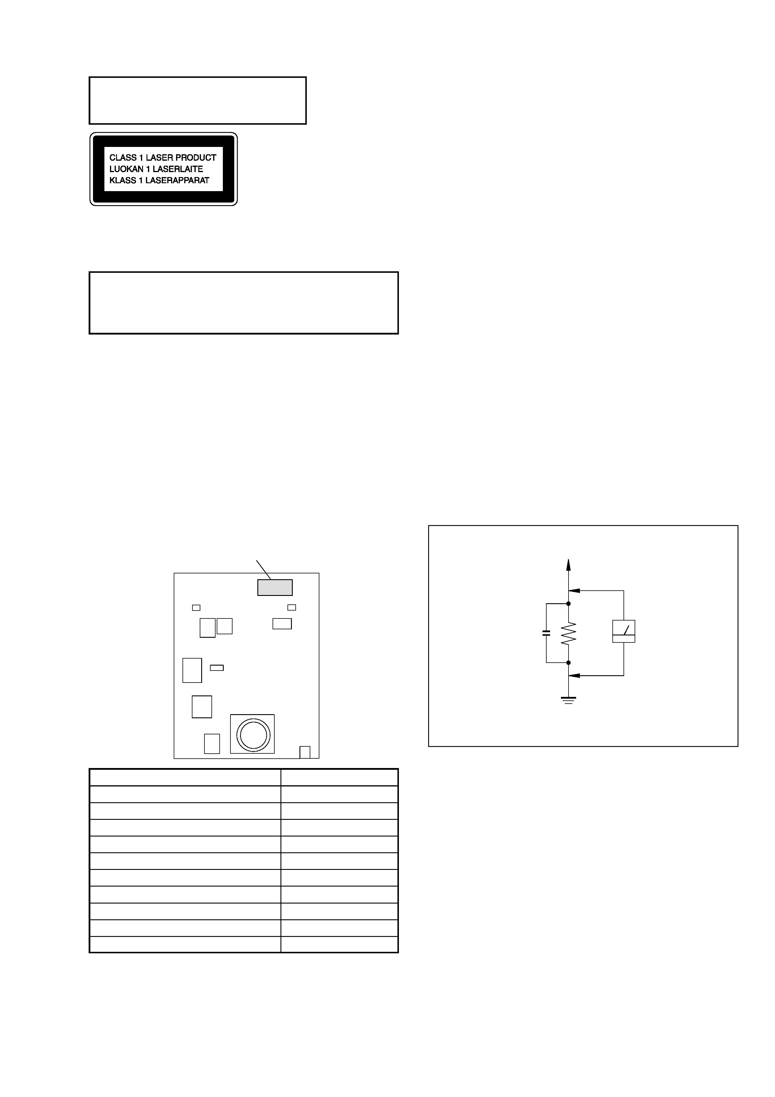
3.
Measuring the voltage drop across a resistor by means of a
VOM or battery-operated AC voltmeter. The "limit" indication
is 0.75 V, so analog meters must have an accurate low-voltage
scale. The Simpson 250 and Sanwa SH-63Trd are examples of
a passive VOM that is suitable. Nearly all battery operated
digital multimeters that have a 2V AC range are suitable. (See
Fig. A)
SAFETY CHECK-OUT
(US model only)
To Exposed Metal
Parts on Set
0.15
µF
1.5 k
AC
Voltmeter
(0.75 V)
Earth Ground
Fig. A. Using an AC voltmeter to check AC leakage.
Notes on chip component replacement
· Never reuse a disconnected chip component.
· Notice that the minus side of a tantalum capacitor may be damaged
by heat.