1
SERVICE MANUAL
US Model
Canadian Model
AEP Model
UK Model
MGS-X1
System
"Memory Stick" digital audio system
Sampling frequency response
44.1 kHz
Recording format
Adaptive Transform Acorstick Cording3
(ATRAC3)
Frequency response
20 to 20,000 Hz
Signal-to-noise ratio (S/N)
More than 80 dB (excluding 66 kbps)
Power consumption
Less than 300 mA (during playback)
Operating temperature
10 °C to +55 °C
Dimensions
Approx. 48.1
× 30.5 × 113.5 mm (w/h/d)
(1 15/16
× 1 1/4 × 4 1/2 in.)
Mass
Approx. 210 g (7.4 oz.)
Supplied accessories
Parts for installation and connections (1 set)
Carrying pouch (1)
Optional accessories
Source selector
XA-C30
Bus/Pin extension cord (2 m)
RC-87
"MG Memory Stick"
MSG-32A (32 MB) MSG-64A (64 MB)
MSG 128A (128 MB)
Design and specifications are subject to change without notice.
SPECIFICATIONS
Ver 1.0 2001.09
Sony Corporation
e Vehicle Company
Shinagawa Tec Service Manual Production Group
9-873-325-01
2001I0400-1
© 2001.9
MG MEMORY STICK
SYSTEM-UP PLAYER

2
TABLE OF CONTENTS
1. SERVICE NOTE ................................................................ 3
2. GENERAL
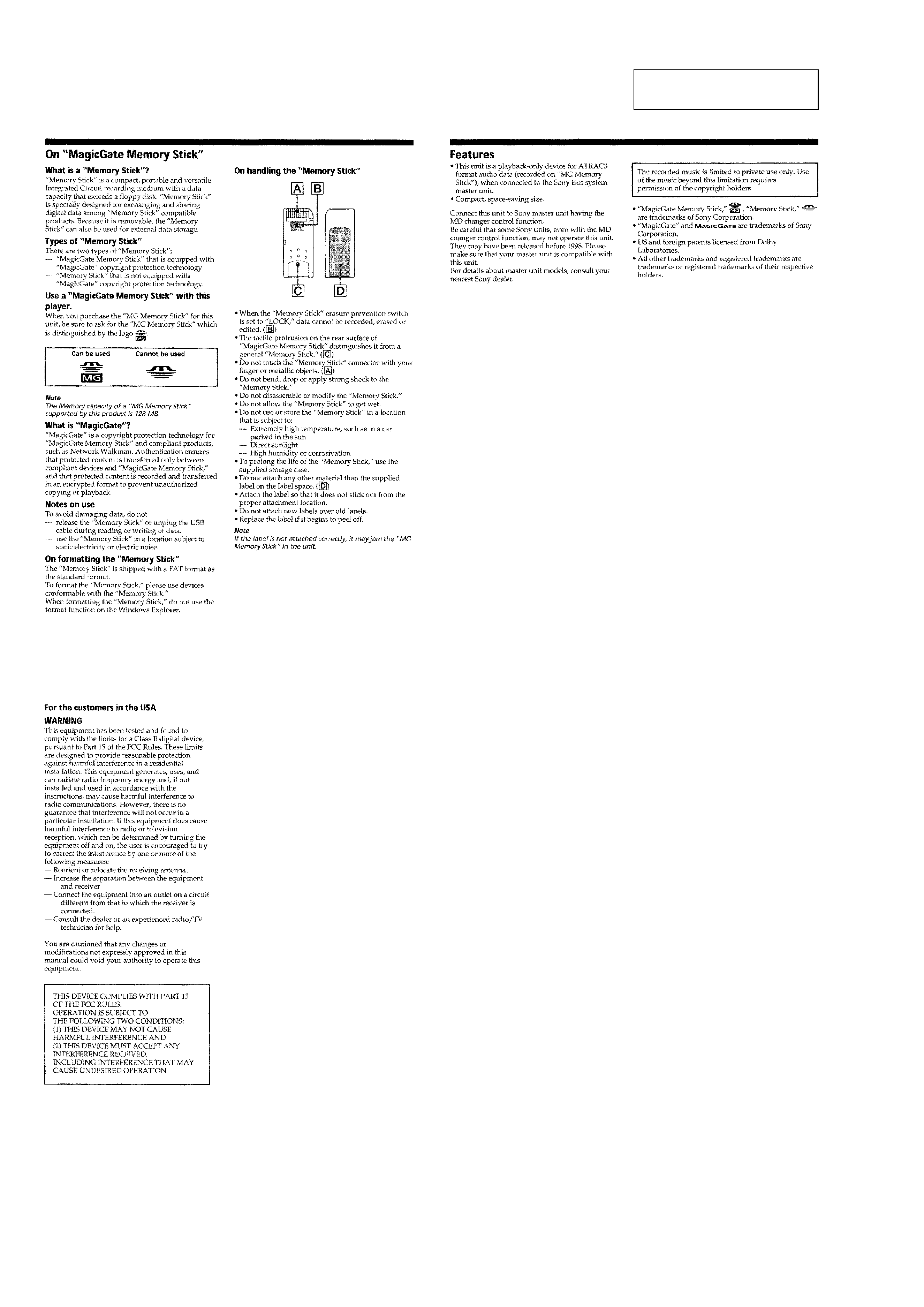
On "MagicGate Memory Stick" .............................................. 4
Features ................................................................................... 4
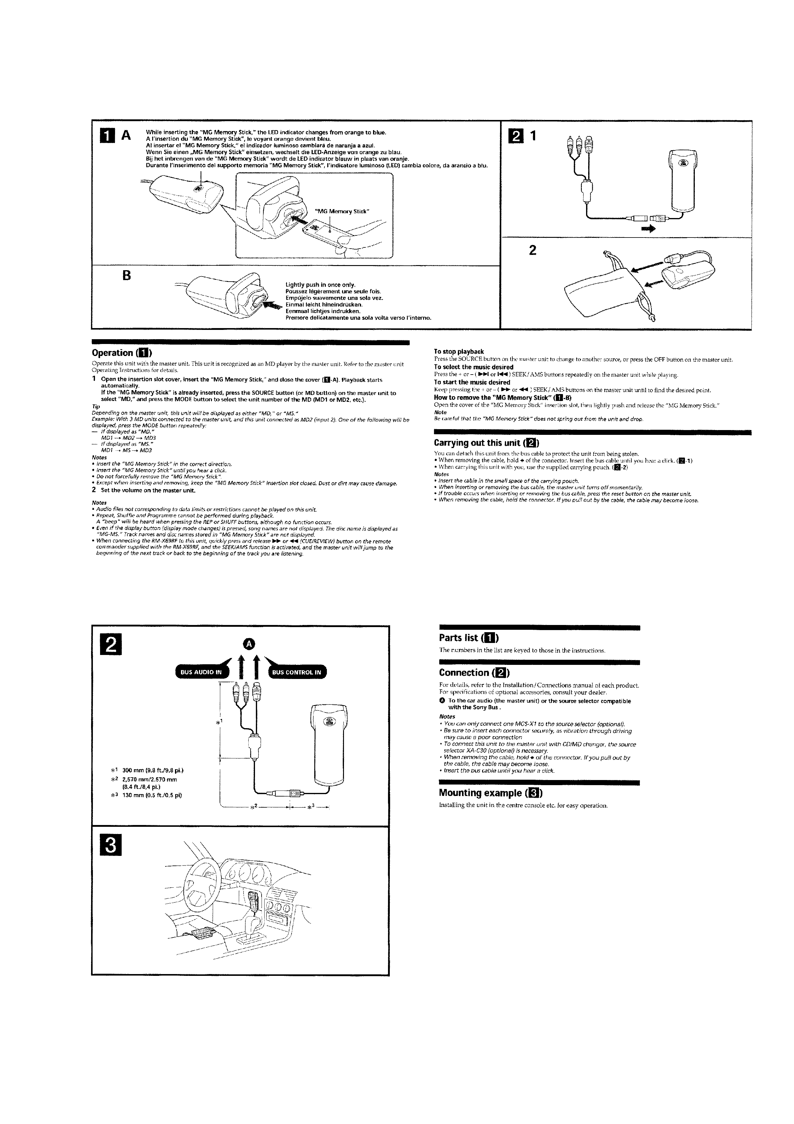
Operation ................................................................................. 5
Connection ............................................................................... 5
3. DISASSEMBLY
3-1. Case (Bottom) ..................................................................... 7
3-2. IF Board .............................................................................. 7
3-3. Main Board ......................................................................... 8
3-4. LED Board .......................................................................... 8
4. DIAGRAMS
4-1. IC Pin Descriptions ............................................................. 9
4-2. Block Diagram Main Section ...................................... 17
4-3. Block Diagram IF Section ........................................... 18
4-4. Printed Wiring Board Main Section ............................ 21
4-5. Schematic Diagram Main Section (1/4) ...................... 22
4-6. Schematic Diagram Main Section (2/4) ...................... 23
4-7. Schematic Diagram Main Section (3/4) ...................... 24
4-8. Schematic Diagram Main Section (4/4) ...................... 25
4-9. Printed Wiring Board IF Section ................................. 26
4-10. Printed Wiring Board LED Section ............................. 27
4-11. Schematic Diagram IF, LED Section .......................... 28
5. EXPLODED VIEW
5-1. Main Section ..................................................................... 32
6. ELECTRICAL PARTS LIST ........................................ 33
SAFETY-RELATED COMPONENT WARNING!!
COMPONENTS IDENTIFIED BY MARK 0 OR DOTTED LINE
WITH MARK 0 ON THE SCHEMATIC DIAGRAMS AND IN
THE PARTS LIST ARE CRITICAL TO SAFE OPERATION.
REPLACE THESE COMPONENTS WITH SONY PARTS WHOSE
PART NUMBERS APPEAR AS SHOWN IN THIS MANUAL OR
IN SUPPLEMENTS PUBLISHED BY SONY.
Notes on Chip Component Replacement
· Never reuse a disconnected chip component.
· Notice that the minus side of a tantalum capacitor may be dam-
aged by heat.
MGS-X1
ATTENTION AU COMPOSANT AYANT RAPPORT
À LA SÉCURITÉ!!
LES COMPOSANTS IDENTIFIÉS PAR UNE MARQUE 0 SUR LES
DIAGRAMMES SCHÉMATIQUES ET LA LISTE DES PIÈCES SONT
CRITIQUES POUR LA SÉCURITÉ DE FONCTIONNEMENT. NE
REMPLACER CES COMPOSANTS QUE PAR DES PIÈCES SONY
DONT LES NUMÉROS SONT DONNÉS DANS CE MANUEL OU
DANS LES SUPPLÉMENTS PUBLIÉS PAR SONY.
· UNLEADED SOLDER
Boards requiring use of unleaded solder are printed with the lead-
free mark (LF) indicating the solder contains no lead.
(Caution: Some printed circuit boards may not come printed with
the lead free mark due to their particular size.)
: LEAD FREE MARK
Unleaded solder has the following characteristics.
· Unleaded solder melts at a temperature about 40°C higher than
ordinary solder.
Ordinary soldering irons can be used but the iron tip has to be
applied to the solder joint for a slightly longer time.
Soldering irons using a temperature regulator should be set to
about 350°C.
Caution: The printed pattern (copper foil) may peel away if
the heated tip is applied for too long, so be careful!
· Strong viscosity
Unleaded solder is more viscous (sticky, less prone to flow)
than ordinary solder so use caution not to let solder bridges
occur such as on IC pins, etc.
· Usable with ordinary solder
It is best to use only unleaded solder but unleaded solder may
also be added to ordinary solder.
3
MGS-X1
SECTION 1
SERVICE NOTE
· Replacement
of
MBM29LV400BC-90PBT
(IC5000),
HY62UF16201ALLF (IC5600), CXD9534CGG (IC7001) and
CXD1859GA (IC8000) on main board used in this set requires a
special tool. Therefore, they cannot be replaced.
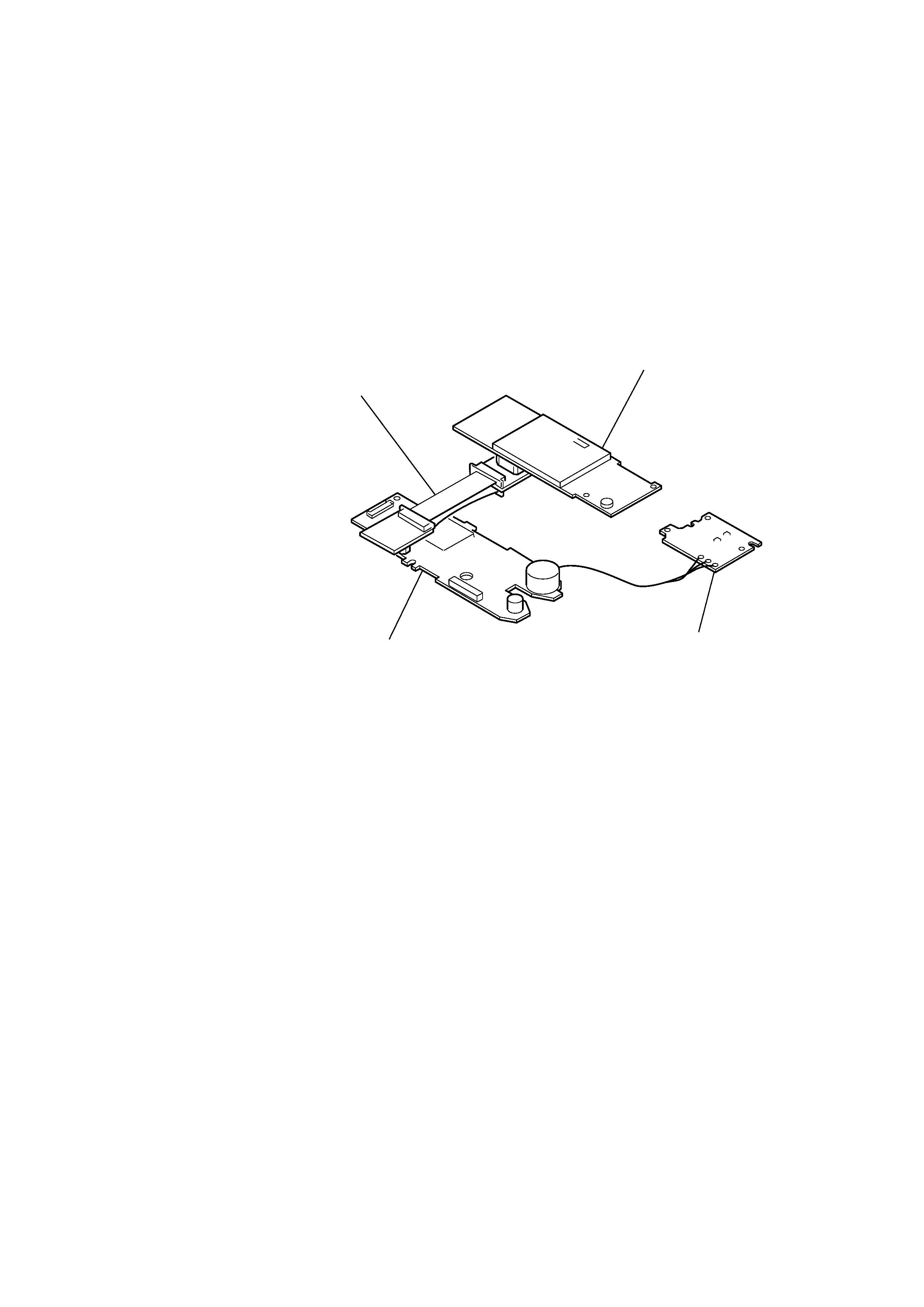
· When performing operational checks with the main and IF boards
removed, install the service jig (relay board for main and IF board
connection) between main board (CN100) and IF board (CN501)
as shown in the figure below.
MAIN board
LED board
IF board
Service jig
( Relay board for main and IF board connection)
4
MGS-X1
SECTION 2
GENERAL
This section extracted from
instruction manual.
5
MGS-X1
Connection