MGS-X1
MG Memory Stick
System-up Player
Installation/Connections
Installation/Connexions
Instalación/Conexiones
Installation/Anschluß
Montage/Aansluitingen
Installazione/Collegamenti
Sony Corporation
2001 Printed in Japan
13
2
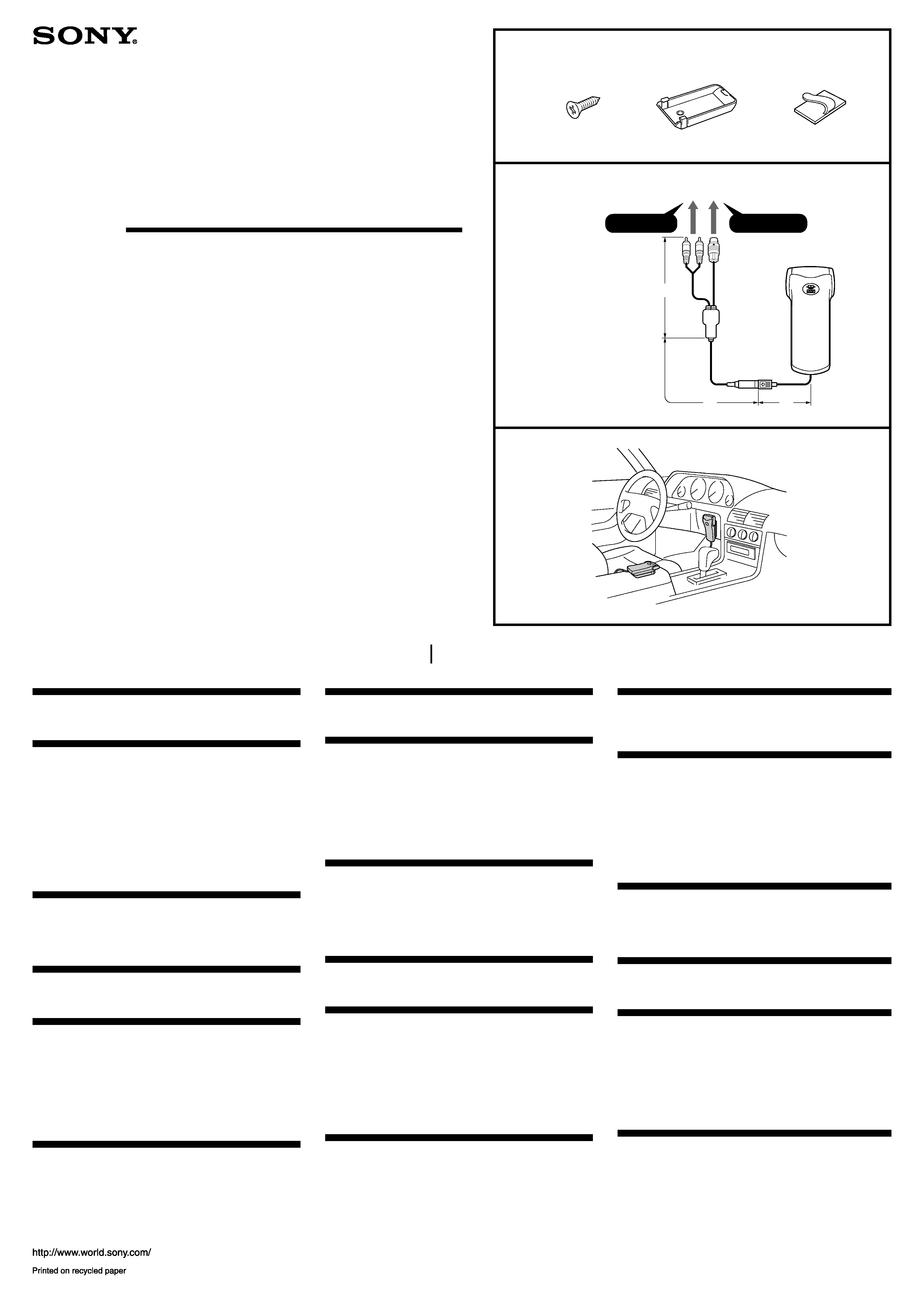
Parts list (1)
The numbers in the list are keyed to those in the instructions.
Connection (2)
For details, refer to the Installation/Connections manual of each
product. For specifications of optional accessories, consult your
dealer.
A
To the car audio (the master unit) or the source selector compatible
with the Sony Bus .
Notes
· You can only connect one MGS-X1 to the source selector (optional).
· Be sure to insert each connector securely, as vibration through driving
may cause a poor connection.
· To connect this unit to the CD/MD changer, the source selector XA-C30
(optional) is necessary.
Mounting example (3)
Installing the unit in the centre console etc. for easy operation.
Liste des composants (1)
Les numéros de la liste correspondent à ceux des instructions.
Connection (2)
Pour plus de détails, consulter le manuel d'installation/connexions
de chaque produit. ##<FR-1>##
A
Vers le système audio voiture (appareil principal) compatible avec le
bus Sony ou le sélecteur de source.
Remarques
· ##<FR-2>##
· ###
· ###
Exemple de montage (3)
##<FR-3>##
1
3
2
× 2
Lista de componentes (1)
Los números de la lista corresponden a los de las instrucciones.
Connection (2)
Con respecto a los detalles, consulte el manual de instalación/
conexiones de cada producto. ##<ES-1>##
A
Al sistema de audio del automóvil (unidad principal) compatible con el
Bus de Sony o con el selector de fuente.
Notas
· ##<ES-2>##
· ###
· ###
Ejemplo de montaje (3)
##<ES-3>##
Teileliste (1)
Die Nummern in der Liste sind dieselben wie im Erläuterungstext.
Connection (2)
Einzelheiten entnehmen Sie der Installations-/Anschlußanleitung
des betreffenden Geräts. ##<DE-1>##
A
an Autoanlage (Hauptgerät), die mit dem Sony-Bus oder dem
Signalquellenwähler kompatibel ist.
Hinweis
· ##<DE-2>##
· ###
· ###
Anschlußbeispiel (3)
##<DE-3>##
BUS AUDIO IN
BUS CONTROL IN
A
Onderdelenlijst (1)
De nummers in de afbeelding verwijzen naar die in de montage-
aanwijzingen.
Connection (2)
Zie voor nadere bijzonderheden de gebruiksaanwijzing voor
installatie en aansluitingen van de aan te sluiten apparatuur. ##<NL-
1>##
A
Op het car audiosysteem (hoofdtoestel) dat compatibel is met Sony Bus
of de bronkeuzeschakelaar
Opmerkings
· ##<NL-2>##
· ###
· ###
Voorbeeldaansluitingen (3)
##<NL-3>##
Elenco dei componenti (1)
I numeri nell'elenco corrispondono a quelli riportati nelle istruzioni.
Connection (2)
Per i dettagli, fare riferimento al manuale di installazione/
collegamenti dell'autoradio. ##<IT-1>##
A
All'autoradio (unità principale) compatibile con bus Sony o con il
selettore di sorgente.
Notas
· ##<IT-2>##
· ###
· ###
Esempi di collegamento (3)
##<IT-3>##
*
1
*
2
*
3
*
1 300 mm (9.8 ft./9,8 pi.)
*
2 2,570 mm/2.570 mm
(8.4 ft./8,4 pi.)
*
3 130 mm (0.5 ft./0,5 pi)
*I-3-237-758-11*
(1)
4
Precautions
·Choose the mounting location carefully, observing the following:
--Do not install the unit where;
·it will interfere with normal driving operations.
·it will injure driver or passengers.
·the ambient temperature exceeds 55 °C (131 F°).
·it will be exposed to direct sunlight or hot air from a heater.
·it will be exposed to rain, water, or high humidity.
·it will be exposed to a lot of dust.
·it will become magnetized.
·it will be subject to excessive vibration.
·there are wire harnesses or pipelines under the place.
·it will jam any working parts of the car.
·it will get the wires under a screw, or caught in moving parts.
·Use only the supplied mounting hardware for a safe and secure
installation.
·If the unit is installed at an angle, when inserting and removing the
"MG Memory stick," take care not to drop it.
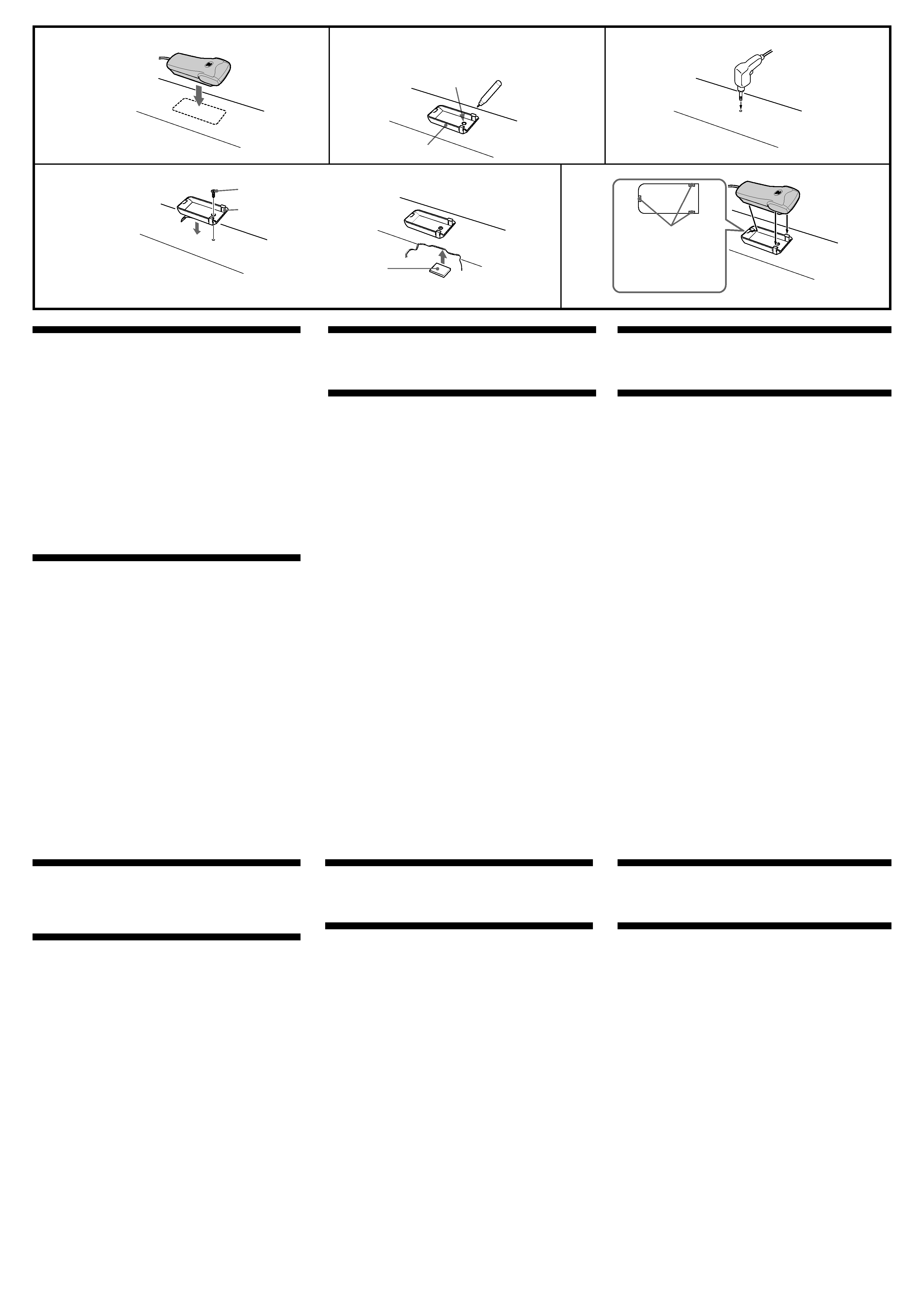
Installation (4)
1 Deciding installation position, and cleaning the installation
area.
Clean the installation area of any dirt or oil before applying
installed tape on the holder 2 (see above illustration 4-4).
Note
Be sure nothing obstructs the handle, lever, etc.
2 Mark the position of screw holes in the installation position.
Use the screw hole of the holder 2 as a template.
3 Make a hole of 2 mm at the marked position.
4 Warm up the surface of the installation position and installed
tape on the holder 2 to between 20 ºC and 30 ºC. Adjust the
holder to the desired position, press down firmly, and install
the supplied screw 1.
After installing the screw, cover the protruding end of the screw
to avoid damage to cords. Gum tape may be used for this
purpose.
5 To install, align the 3 lockup holes on the bottom of the unit
with the 3 holder catches.
Secure the long cord with the supplied cord clamp 3 so that it
does not interfere with driving. Take extra care that the cord does
not become twisted around the gear lever as an accident may
occur.
Précautions
·##<FR-7>##
Installation (4)
##<FR-8>##
Precauciones
· ##<ES-7>##
Instalación (4)
##<ES-8>##
Vorsichtsmaßnahmen
·##<DE-7>##
Installation (4)
##<DE-8>##
Voorzorgsmaatregelen
·##<NL-7>##
Installeren (4)
##<NL-8>##
Precauzioni
·##<IT-7>##
Installazione (4)
##<IT-8>##
4
1
3
5
2
2
screw hole
##<FR-4>##
##<ES-4>##
##<DE-4>##
##<NL-4>##
##<IT-4>##
2
gum tape, etc.
##<FR-5>##
##<ES-5>##
##<DE-5>##
##<NL-5>##
##<IT-5>##
lockup holes
##<FR-6>##
##<ES-6>##
##<DE-6>##
##<NL-6>##
##<IT-6>##
1