SERVICE MANUAL
FM/AM (MW/LW) MINIDISC PLAYER
US Model
AEP Model
UK Model
SPECIFICATIONS
MDX-F5800
Ver 1.1 2004.09
9-877-611-02
Sony Corporation
2004I05-1
e Vehicle Company
© 2004.09
Published by Sony Engineering Corporation
Model Name Using Similar Mechanism
NEW
MD Mechanism Type
MG-165A-138
Optical Pick-up Name
KMS-242E
US and foreign patents licensed from Dolby
Laboratories.
AUDIO POWER SPECIFICATIONS
AUDIO POWER SPECIFICATIONS (US model)
Power requirements
12 V DC car battery
(negative ground)
Dimensions
Approx. 178
× 50 × 181 mm
(7 1/8
× 2 × 7 1/4 in)
(w/h/d)
Mounting dimensions
Approx. 182
× 53 × 161 mm
(7 1/4
× 2 1/8 × 6 3/8 in)
(w/h/d)
Mass
Approx. 1.2 kg
(2 lb 10 oz)
Supplied accessories
Parts for installation and
connections (1 set)
Front panel case (1)
Note
This unit cannot be connected to a digital preamplifier
or an equalizer which is Sony BUS system compatible.
Design and specifications are subject to change
without notice.
Power amplifier section
Outputs
Speaker outputs
(sure seal connectors)
Speaker impedance
4
- 8 ohms
Maximum power output
52 W
× 4 (at 4 ohms)
General
Outputs
Audio output terminals
(front, rear/sub switchable)
Power antenna relay control
terminal
Power amplifier control
terminal
Inputs
Telephone ATT control
terminal
Remote controller input
terminal
BUS control input terminal
BUS audio input terminal
Antenna input terminal
Tone controls
Low:
±10 dB at 60 Hz (XPLOD)
Mid:
±10 dB at 1 kHz (XPLOD)
High:
±10 dB at 10 kHz (XPLOD)
MW/LW (AEP, UK models)
Tuning range
MW: 531
- 1,602 kHz
LW: 153
- 279 kHz
Aerial terminal
External aerial connector
Intermediate frequency
10.7 MHz/450 kHz
Sensitivity
MW: 30
µV
LW: 40
µV
MD Player section
Signal-to-noise ratio
90 dB
Frequency response
10
- 20,000 Hz
Wow and flutter
Below measurable limit
Tuner section
FM
Tuning range
87.5
- 107.9 MHz
Antenna terminal
External antenna connector
Intermediate frequency
10.7 MHz/450 kHz
Usable sensitivity
9 dBf
Selectivity
75 dB at 400 kHz
Signal-to-noise ratio
67 dB (stereo),
69 dB (mono)
Harmonic distortion at 1 kHz
0.5 % (stereo),
0.3 % (mono)
Separation
35 dB at 1 kHz
Frequency response
30
- 15,000 Hz
AM (US model)
Tuning range
530
- 1,710 kHz
Antenna terminal
External antenna connector
Intermediate frequency
10.7 MHz/450 kHz
Sensitivity
30
µV
POWER OUTPUT AND TOTAL HARMONIC DISTORTION 23.2 watts per channel minimum
continuous average power into 4 ohms, 4 channels driven from 20 Hz to 20 kHz with no more than 5%
total harmonic distortion.
2
MDX-F5800
Notes on chip component replacement
· Never reuse a disconnected chip component.
· Notice that the minus side of a tantalum capacitor may be dam-
aged by heat.
Flexible Circuit Board Repairing
· Keep the temperature of the soldering iron around 270 °C dur-
ing repairing.
· Do not touch the soldering iron on the same conductor of the
circuit board (within 3 times).
· Be careful not to apply force on the conductor when soldering
or unsoldering.
SAFETY-RELATED COMPONENT WARNING!!
COMPONENTS IDENTIFIED BY MARK 0 OR DOTTED
LINE WITH MARK 0 ON THE SCHEMATIC DIAGRAMS
AND IN THE PARTS LIST ARE CRITICAL TO SAFE
OPERATION. REPLACE THESE COMPONENTS WITH
SONY PARTS WHOSE PART NUMBERS APPEAR AS
SHOWN IN THIS MANUAL OR IN SUPPLEMENTS PUB-
LISHED BY SONY.
1.
SERVICING NOTES ............................................... 3
2.
GENERAL
Location of Controls .......................................................
4
3.
DISASSEMBLY
3-1. Disassembly Flow ........................................................... 11
3-2. Sub Panel Assy ................................................................ 12
3-3. Mechanism Deck (MG-165A-138) ................................ 12
3-4. MAIN Board ................................................................... 13
3-5. SERVO Board ................................................................. 13
3-6. MD Cover Assy ............................................................... 14
3-7. Float Block ...................................................................... 14
3-8. Lever (LE23) Assy .......................................................... 15
3-9. Holder Assy ..................................................................... 15
3-10. Chucking Arm Assy ........................................................ 16
3-11. Optical Pick-up (KMS-242E) ......................................... 16
3-12. SL Motor Assy (Sled) (M902),
SP Motor Assy (Spindle) (M901) ................................... 17
4.
ELECTRICAL ADJUSTMENTS
Test Mode ........................................................................ 17
MD Section ..................................................................... 17
Tuner Section .................................................................. 17
5.
DIAGRAMS
5-1. Block Diagram SERVO Section ............................... 18
5-2. Block Diagram MAIN Section ................................. 19
5-3. Block Diagram PANEL/BUS CONTROL/
POWER SUPPLY Section ........................................... 20
5-4. Note for Printed Wiring Boards and
Schematic Diagrams ....................................................... 21
5-5. Schematic Diagram SERVO Section (1/2) ............... 22
5-6. Schematic Diagram SERVO Section (2/2) ............... 23
5-7. Printed Wiring Boards SERVO Section ................... 24
5-8. Printed Wiring Boards MAIN Section ..................... 25
5-9. Schematic Diagram MAIN Section (1/3) ................. 26
5-10. Schematic Diagram MAIN Section (2/3) ................. 27
5-11. Schematic Diagram MAIN Section (3/3) ................. 28
5-12. Printed Wiring Board SUB Board ............................ 29
5-13. Schematic Diagram SUB Board ............................... 29
5-14. Printed Wiring Board KEY Board ............................ 30
5-15. Schematic Diagram KEY Board .............................. 31
6.
EXPLODED VIEWS
6-1. Chassis Section ............................................................... 45
6-2. Front Panel Section ......................................................... 46
6-3. Mechanism Deck Section-1 (MG-165A-138) ................ 47
6-4. Mechanism Deck Section-2 (MG-165A-138) ................ 48
6-5. Mechanism Deck Section-3 (MG-165A-138) ................ 49
7.
ELECTRICAL PARTS LIST ............................... 50
TABLE OF CONTENTS
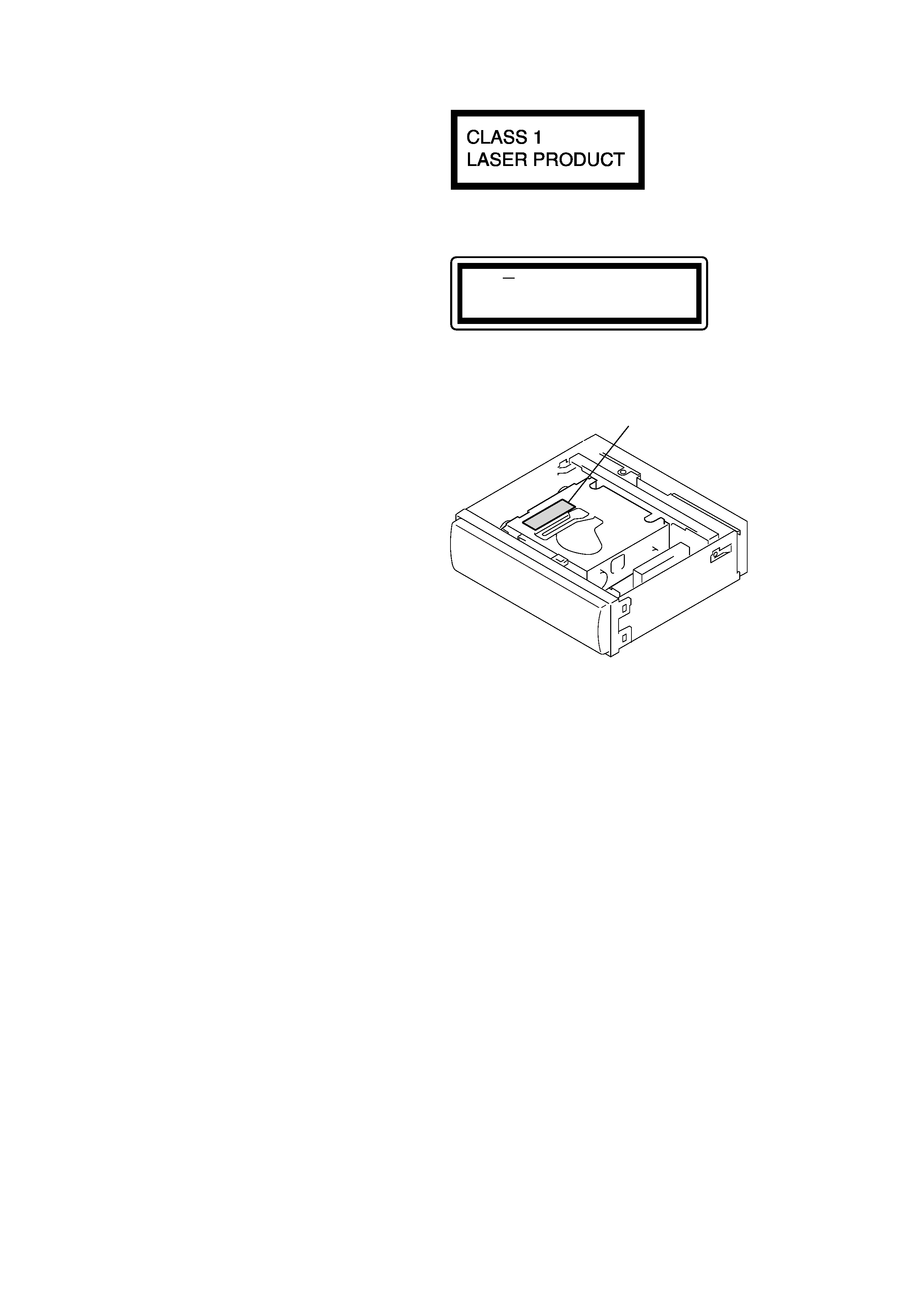
This label is located on the bottom of the
chassis.
This product is classified as a
CLASS 1 LASER PRODUCT.
CAUTION
INVISIBLE
DO NOT STARE INTO BEAM OR
VIEW DIRECTLY WITH OPTICAL INSTRUMENTS
LASER RADIATION WHEN OPEN
This label is located on the drive unit's internal
chassis. (Refer to below figure)
Caution label
Upper view
During service do not take the Optical Pick-up Block apart and do
not adjust the APC circuit. If there is a breakdown in the APC
circuit (including laser diode), replace the entire Optical Pick-up
Block (including SERVO board).
3
MDX-F5800
NOTES ON HANDLING THE OPTICAL PICK-UP
BLOCK OR BASE UNIT
The laser diode in the optical pick-up block may suffer electro-
static break-down because of the potential difference generated
by the charged electrostatic load, etc. on clothing and the human
body.
During repair, pay attention to electrostatic break-down and also
use the procedure in the printed matter which is included in the
repair parts.
The flexible board is easily damaged and should be handled with
care.
NOTES ON LASER DIODE EMISSION CHECK
Never look into the laser diode emission from right avove when
checking it for adustment. It is feared that you will lose your sight.
NOTES ON HANDLING THE OPTICAL PICK-UP BLOCK
(KMS-242E).
The laser diode in the optical pick-up block may suffer electro-
static break-down easily. When handling it, perform soldering
bridge to the laser-tap on the flexible board. Also perform mea-
sures against electrostatic break-down sufficiently before the op-
eration. The flexible board is easily damaged and should be handled
with care.
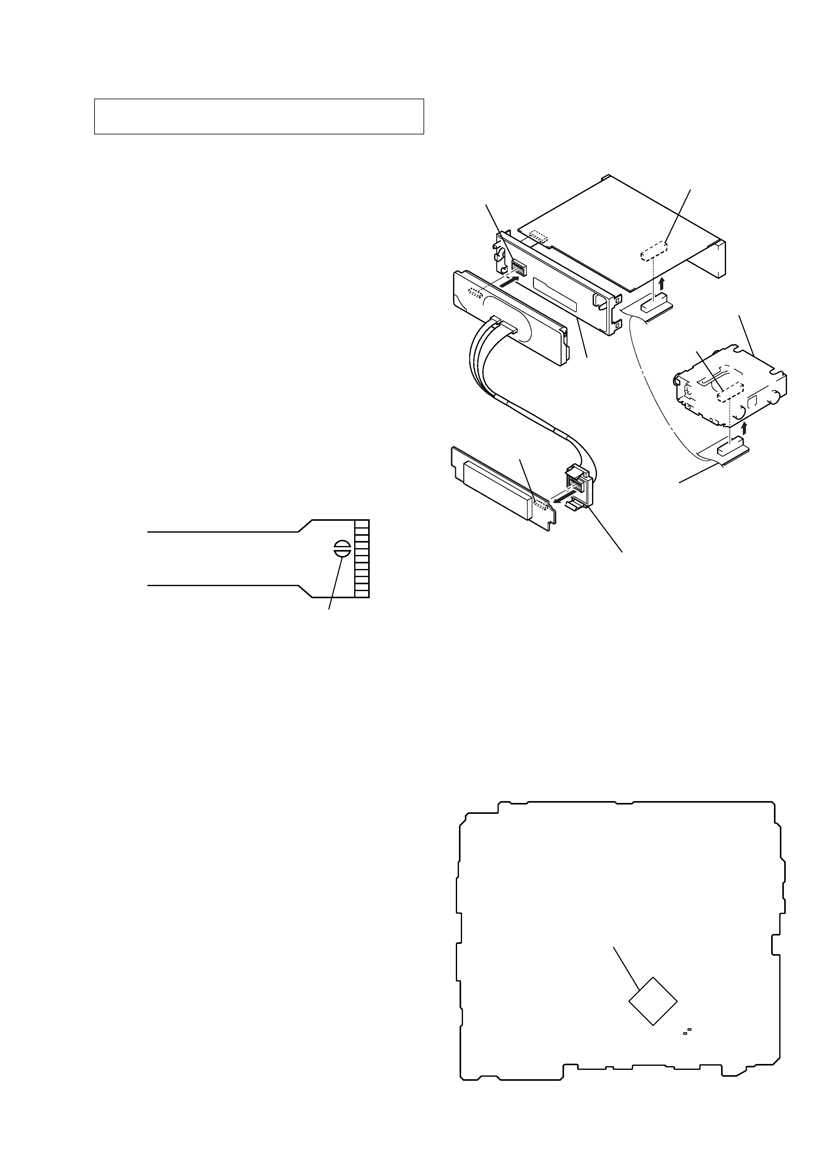
laser-tap
OPTICAL PICK-UP FLEXIBLE BOARD
SERVICE POSITION
In checking the key board and main board, prepare two jigs (con-
nection cable J-2502-011-1 and
connection cable for F/P to main J-2502-071-1).
sub board
(CN801)
mechanism deck
main board (CNP500)
servo board
(CN5)
key board
(CN901)
connect jig
(connection cable
for F/P to main J-2502-071-1)
to the key board (CN900) and
sub board (CN801).
connect jig
(connection cable J-2502-011-1)
to the main board (CNP500) and
servo board (CN5).
sub panel
assy
SECTION 1
SERVICING NOTES
NOTE FOR REPLACING THE IC600
There are two types of IC600 on the MAIN board. In case IC600
is replaced, after surely checking which type of IC600 is mounted
on the set, it exchanges according to the following procedure.
In case of type1:
After surely checking the type of IC600 newly mounted on the
MAIN board, it replaces in the procedure according to each type.
Replacing procedur to type1
1. IC600 is replaced for MN101E01KDJ (PART No. 6-804-093-
01).
Replacing procedur to type2
1. IC600 is replaced for MN101E01JRD1 (PART No. 6-804-511-
02).
2. C606 is replaced for ceramic chip 15PF (PART No. 1-162-
917-11).
3. C607 is replaced for ceramic chip 12PF (PART No. 1-162-
916-11).
In case of type2:
Replacing procedure
1. IC600 is replaced for MN101E01JRD1 (PART No. 6-804-511-
02).
Ver 1.1
MAIN Board (Conductor Side)
IC600
C606
C607
MN101E01KDJ : TYPE1
MN101E01JRD1 : TYPE2
4
MDX-F5800
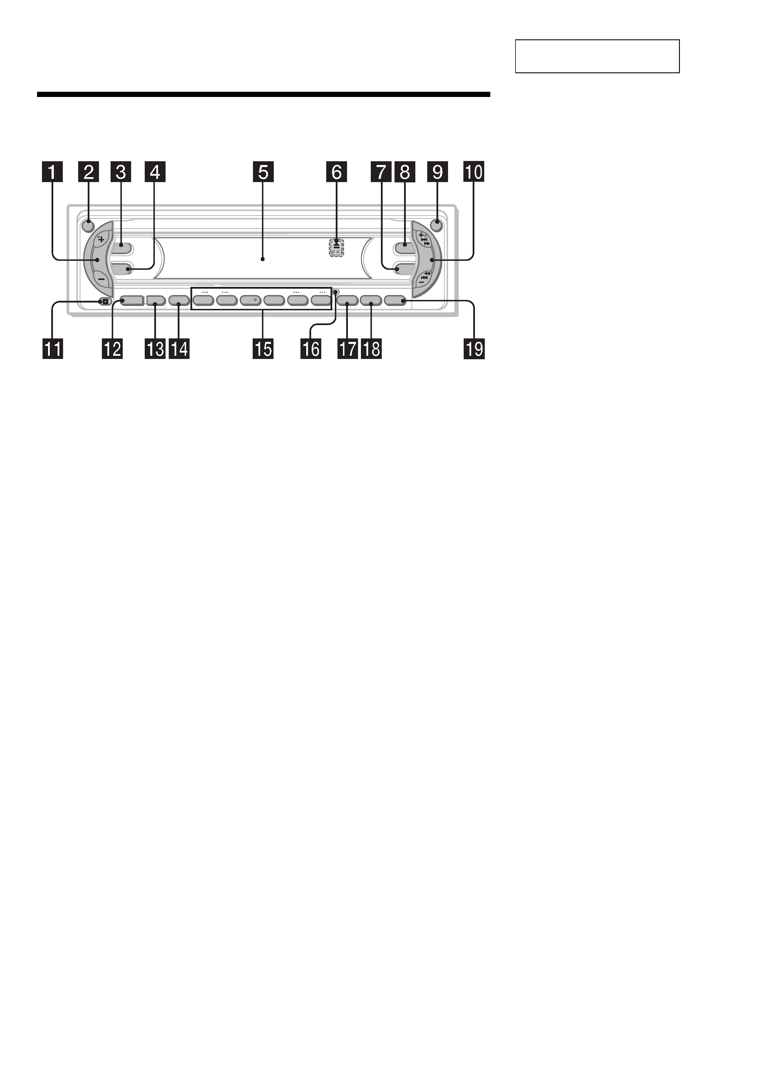
Location of controls
Refer to the pages listed for details.
a Volume +/ button
b ATT (attenuate) button
c DSPL (display mode change) button
d SEL (select) button
To select items.
e Display window
f Z (eject) button (located on the front side
of the unit, behind the front panel)
g EQ3 button
h DSO button
i OPEN button
j SEEK +/ button
Radio:
To tune in stations automatically/find a
station manually.
MD/CD (MP3 files*1):
To skip tracks/fast-forward, reverse a track.
k Receptor for the card remote
commander
l SOURCE (Power on/Radio/MD/CD*2)
button
To select the source.
m MODE button
To change operation.
n OFF (Stop/Power off) button*3
o Number buttons
Radio:
To store the desired station on each number
button.
MD/CD (MP3 files*1):
(1): DISC
(2): DISC +
(3): REP 11
(4): SHUF 12
(5): GP*4/ALBM*1
(6): GP*4/ALBM*1 +
p RESET button (located on the front side of
the unit, behind the front panel)
q B
AF/TA button (AEP, UK models)
TM button (US model)
r S
SENS/BTM button (AEP, UK models)
ENS button (US model)
s LIS
PTY (programme type)/LIST button
(AEP, UK models)
T/CAT*5 button (US model)
*1 Available only when an optional CD unit with the
MP3 file control function is connected, and MP3 file
is played.
*2 When an optional CD unit is connected.
*3
Warning when installing in a car without
an ACC (accessory) position on the
ignition switch
After turning off the ignition, be sure to press
and hold (OFF) on the unit until the display
disappears.
Otherwise, the display does not turn off and this
causes battery drain.
*4 Available only when an MD containing groups is
inserted in this unit and played.
*5 The CAT button is available only when the XM
tuner is connected.
DSPL
SEL
DSO
EQ3
ATT
OPEN
SEEK
SOURCE
MODE
OFF
1
2
3
4
5
6
BTM
SENS
LIST
+
DISC
REP
SHUF
BTM
LIST
+
GP/ALBM
CAT
SECTION 2
GENERAL
This section is extracted from
instruction manual.
5
MDX-F5800
AUDIO OUT REAR
AUDIO OUT FRONT
BUS AUDIO IN
BUS CONTROL IN
BUS CONTROL IN
BUS AUDIO IN
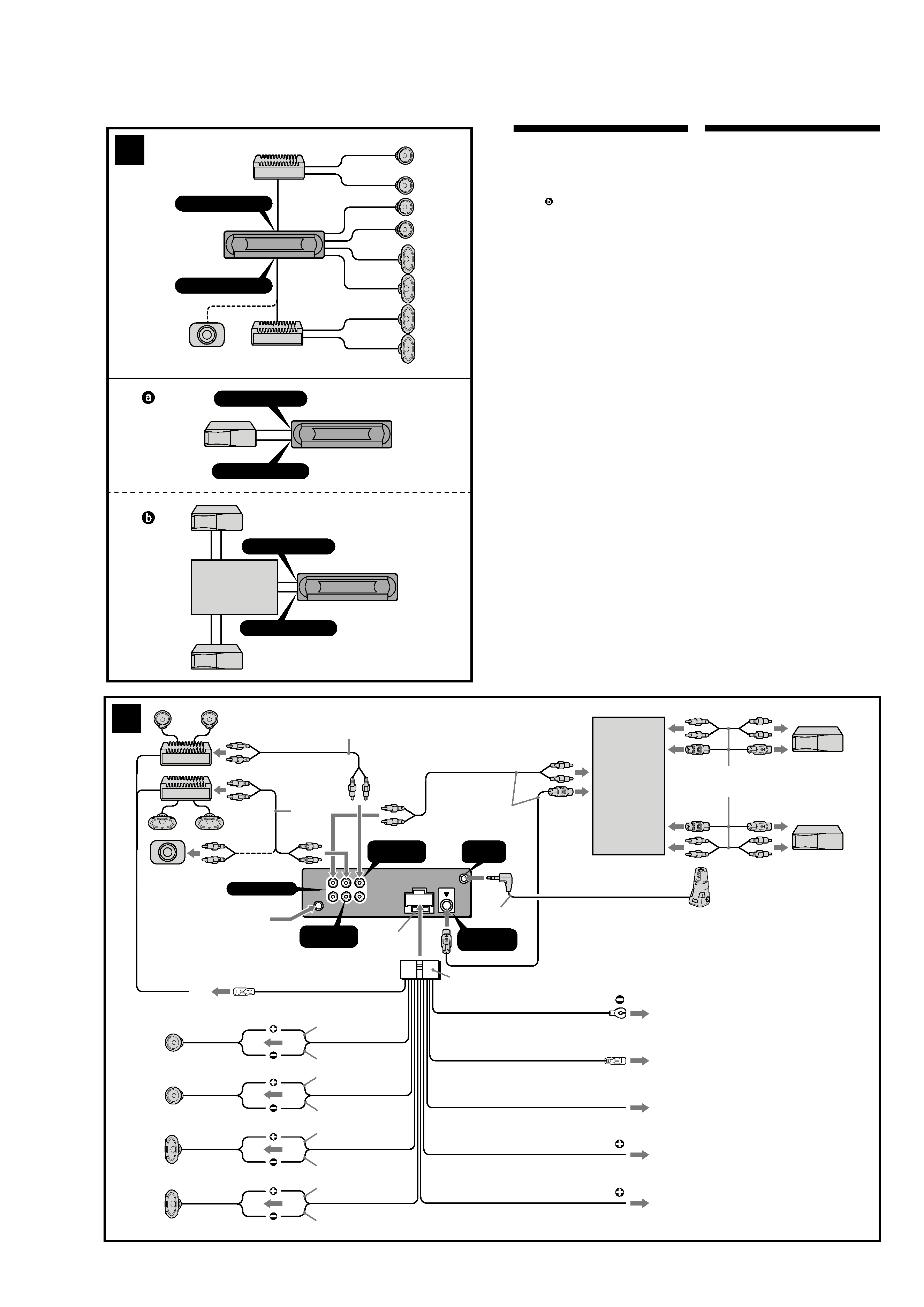
2
A
B
Source selector*
Sélecteur de source*
Selector de fuente*
XA-C30
* not supplied
(US model)
Connection example (2)
Notes (2-A)
· Be sure to connect the ground lead before connecting
the amplifier.
· If you connect an optional power amplifier and do not
use the built-in amplifier, the beep sound will be
deactivated.
Tip (2-B-
)
For connecting two or more MD/CD changers, the source
selector XA-C30 (optional) is necessary.
Connection diagram (3)
1 To a metal surface of the car
First connect the black ground lead, then connect
the yellow and red power input leads.
2 To the power antenna control lead or power
supply lead of antenna booster amplifier
Notes
· It is not necessary to connect this lead if there is no
power antenna or antenna booster, or with a
manually-operated telescopic antenna.
·When your car has a built-in FM/AM antenna in
the rear/side glass, see "Notes on the control and
power supply leads."
3 To AMP REMOTE IN of an optional power
amplifier
This connection is only for amplifiers. Connecting
any other system may damage the unit.
4 To the interface cable of a car telephone
5 To the +12 V power terminal which is energized
in the accessory position of the ignition key
switch
Notes
· If there is no accessory position, connect to the +12
V power (battery) terminal which is energized at
all times.
Be sure to connect the black ground lead to a
metal surface of the car first.
·When your car has a built-in FM/AM antenna in
the rear/side glass, see "Notes on the control and
power supply leads."
6 To the +12 V power terminal which is energized
at all times
Be sure to connect the black ground lead to a metal
surface of the car first.
Notes on the control and power supply leads
· The power antenna control lead (blue) supplies +12 V
DC when you turn on the tuner.
·When your car has built-in FM/AM antenna in the rear/
side glass, connect the power antenna control lead
(blue) or the accessory power input lead (red) to the
power terminal of the existing antenna booster. For
details, consult your dealer.
·A power antenna without a relay box cannot be used
with this unit.
Memory hold connection
When the yellow power input lead is connected, power
will always be supplied to the memory circuit even when
the ignition switch is turned off.
Notes on speaker connection
· Before connecting the speakers, turn the unit off.
· Use speakers with an impedance of 4 to 8 ohms, and
with adequate power handling capacities to avoid its
damage.
· Do not connect the speaker terminals to the car
chassis, or connect the terminals of the right speakers
with those of the left speaker.
· Do not connect the ground lead of this unit to the
negative () terminal of the speaker.
· Do not attempt to connect the speakers in parallel.
· Connect only passive speakers. Connecting active
speakers (with built-in amplifiers) to the speaker
terminals may damage the unit.
·To avoid a malfunction, do not use the built-in speaker
leads installed in your car if the unit shares a common
negative () lead for the right and left speakers.
· Do not connect the unit's speaker leads to each other.
Note on connection
If speaker and amplifier are not connected correctly,
"FAILURE" appears in the display. In this case, make sure
the speaker and amplifier are connected correctly.
L
R
BUS AUDIO IN
AUDIO OUT
FRONT
AUDIO OUT
REAR
*2
BUS
CONTROL IN
REMOTE
IN
3
Source selector
(not supplied)
XA-C30
AMP REM
Max. supply current 0.3 A
Fuse (10 A)
Blue/white striped
Supplied with the MD/CD changer
3
from car antenna
5
6
4
ANT REM
4
ATT
1
*1
Red
Yellow
Black
Blue
White
Green
Purple
White/black striped
Gray/black striped
Green/black striped
Gray
Left
Right
Left
Right
Light blue
Max. supply current 0.1 A
*3
2
Purple/black striped
*1
Supplied with XA-C30
*1 RCA pin cord (not supplied)
*2 AUDIO OUT can be switched to REAR
or SUB.
For details, see the supplied operating
instructions.
*3 Insert with the cord downwards.