SERVICE MANUAL
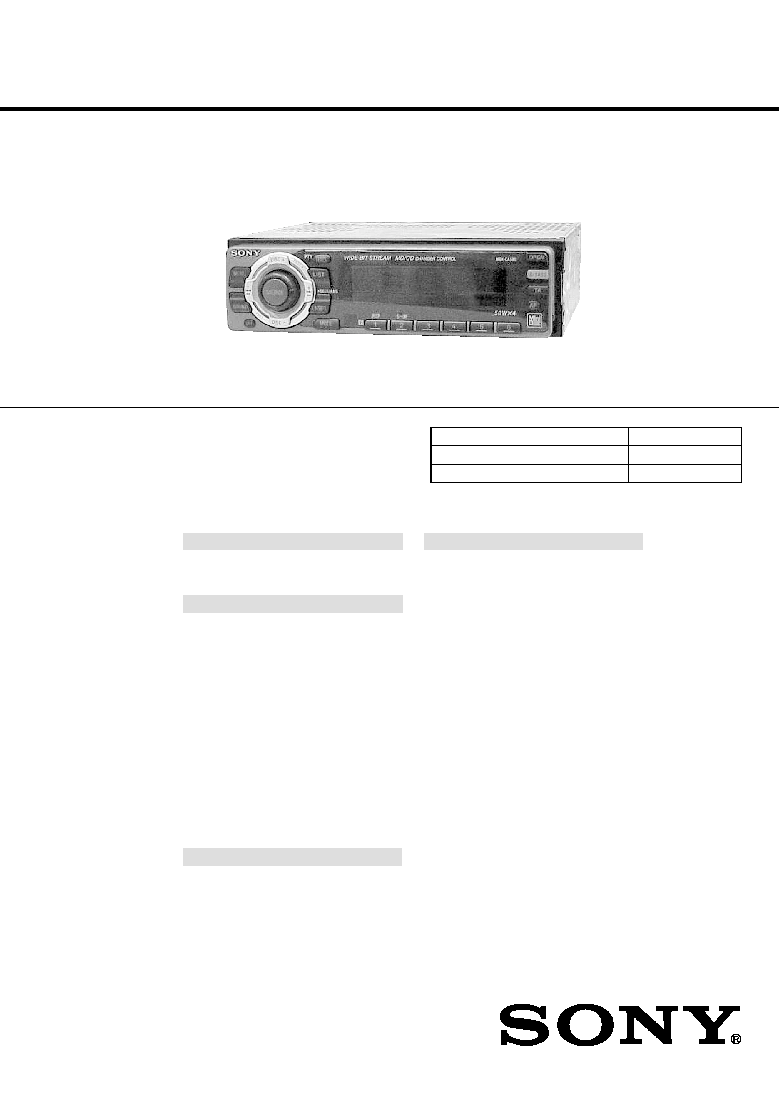
FM/MW/LW MINIDISC PLAYER
AEP Model
UK Model
SPECIFICATIONS
MDX-CA580
Model Name Using Similar Mechanism
NEW
Base Mechanism Type
MG-164NA-138
Optical Pick-up Name
KMS-241C
MD player section
Signal-to-noise ratio
90 dB
Frequency response
10 20,000 Hz
Wow and flutter
Below measurable limit
Tuner section
FM
Tuning range
87.5 108.0 MHz
Aerial terminal
External aerial connector
Intermediate frequency
10.7 MHz/450 kHz
Usable sensitivity
8 dBf
Selectivity
75 dB at 400 kHz
Signal-to-noise ratio
66 dB (stereo),
72 dB (mono)
Harmonic distortion at 1 kHz
0.6 % (stereo),
0.3 % (mono)
Separation
35 dB at 1 kHz
Frequency response
30 15,000 Hz
MW/LW
Tuning range
MW: 531 1,602 kHz
LW: 153 279 kHz
Aerial terminal
External aerial connector
Intermediate frequency
10.7 MHz/450 kHz
Sensitivity
MW: 30
µV
LW: 40
µV
Power amplifier section
Outputs
Speaker outputs
(sure seal connectors)
Speaker impedance
4 8 ohms
Maximum power output 50 W
× 4 (at 4 ohms)
General
Outputs
Audio outputs
Power aerial relay control
lead
Power amplifier control
lead
Telephone ATT control
lead
Tone controls
Bass
±9 dB at 100 Hz
Treble
±9 dB at 10 kHz
Power requirements
12 V DC car battery
(negative ground)
Dimensions
Approx. 178
× 50 × 183 mm
(w/h/d)
Mounting dimensions
Approx. 182
× 53 × 162 mm
(w/h/d)
Mass
Approx. 1.2 kg
Supplied accessories
Parts for installation and
connections (1 set)
Front panel case (1)
Design and specifications are subject to change
without notice.
U.S. and foreign patents licensed from Dolby laboratories
Licensing Corporation.
Ver 1.1 2001.05
9-870-228-12
Sony Corporation
2001E0500-1
e Vehicle Company
C
2001.5
Shinagawa Tec Service Manual Production Group
2
Notes on chip component replacement
· Never reuse a disconnected chip component.
· Notice that the minus side of a tantalum capacitor may be dam-
aged by heat.
Flexible Circuit Board Repairing
· Keep the temperature of the soldering iron around 270 °C dur-
ing repairing.
· Do not touch the soldering iron on the same conductor of the
circuit board (within 3 times).
· Be careful not to apply force on the conductor when soldering
or unsoldering.
NOTES ON HANDLING THE OPTICAL PICK-UP
BLOCK OR BASE UNIT
SAFETY-RELATED COMPONENT WARNING!!
COMPONENTS IDENTIFIED BY MARK 0 OR DOTTED
LINE WITH MARK 0 ON THE SCHEMATIC DIAGRAMS
AND IN THE PARTS LIST ARE CRITICAL TO SAFE
OPERATION. REPLACE THESE COMPONENTS WITH
SONY PARTS WHOSE PART NUMBERS APPEAR AS
SHOWN IN THIS MANUAL OR IN SUPPLEMENTS PUB-
LISHED BY SONY.
CAUTION
Use of controls or adjustments or performance of procedures
other than those specified herein may result in hazardous ra-
diation exposure.
The laser diode in the optical pick-up block may suffer electro-
static break-down because of the potential difference generated
by the charged electrostatic load, etc. on clothing and the human
body.
During repair, pay attention to electrostatic break-down and also
use the procedure in the printed matter which is included in the
repair parts.
The flexible board is easily damaged and should be handled with
care.
NOTES ON LASER DIODE EMISSION CHECK
Never look into the laser diode emission from right avove when
checking it for adustment. It is feared that you will lose your sight.
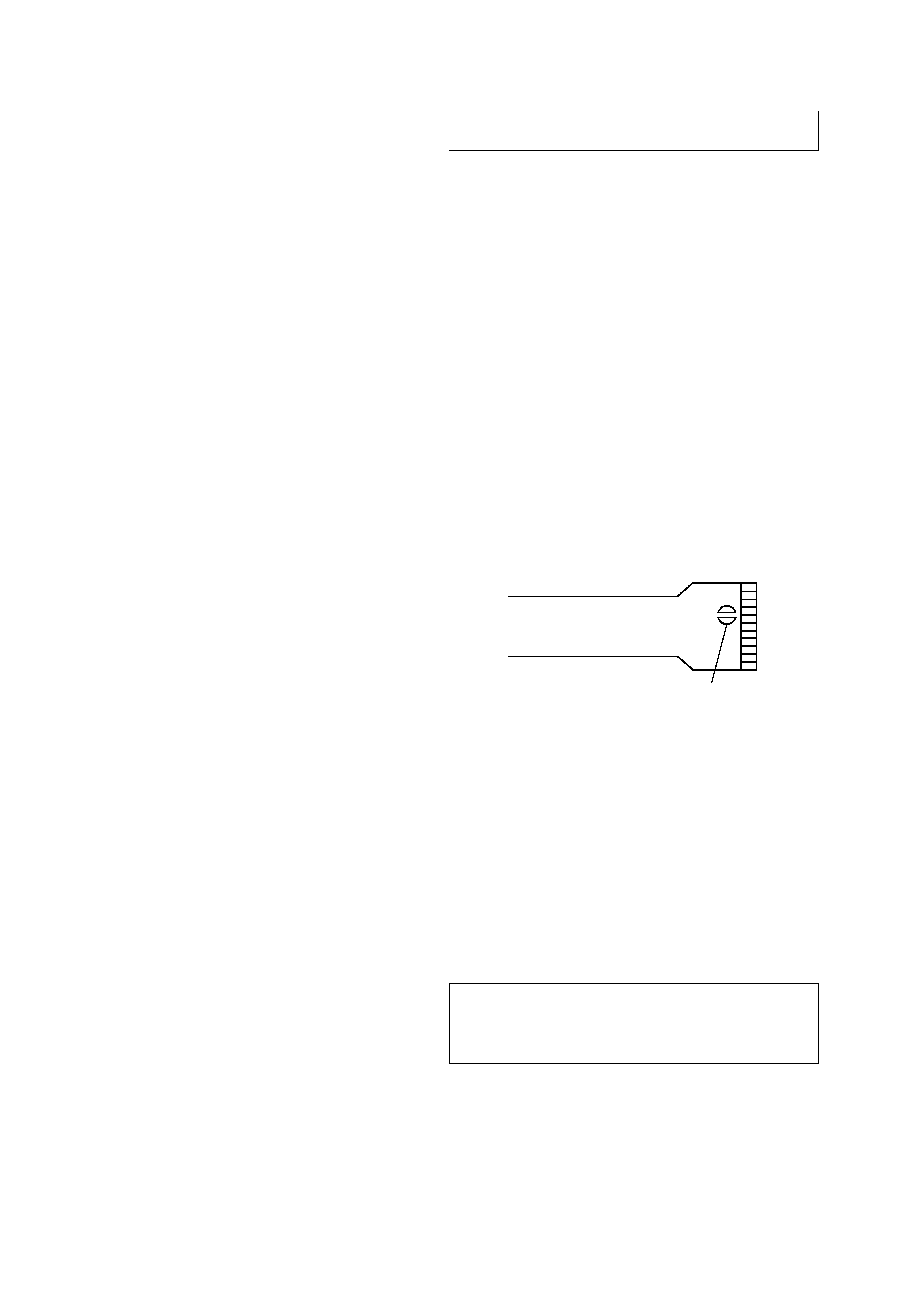
NOTES ON HANDLING THE OPTICAL PICK-UP BLOCK
(KMS-241C).
The laser diode in the optical pick-up block may suffer electro-
static break-down easily. When handling it, perform soldering
bridge to the laser-tap on the flexible board. Also perform
m easur es against electrostatic break-down sufficiently before the
operation. The flexible board is easily damaged and should be
handled with care.
laser-tap
OPTICAL PICK-UP FLEXIBLE BOARD
1.
GENERAL
Location of Controls .......................................................
3
Setting the Clock .............................................................
3
Installation .......................................................................
4
Connections .....................................................................
5
2.
DISASSEMBLY ......................................................... 9
3.
ELECTRICAL ADJUSTMENTS
Test Mode ........................................................................ 16
MD Section ..................................................................... 16
Tuner Section .................................................................. 16
4.
DIAGRAMS
4-1. Block Diagram SERVO Section ............................... 17
4-2. Block Diagram TUNER Section .............................. 18
4-3. Block Diagram MAIN Section ................................. 19
4-4. Block Diagram BUS CONTROL/
POWER SUPPLY Section ........................................... 20
4-5. Note for Printed Wiring Boards and
Schematic Diagrams ....................................................... 22
4-6. Printed Wiring Boards SERVO Section ................... 23
4-7. Schematic Diagram SERVO Section (1/2) ............... 24
4-8. Schematic Diagram SERVO Section (2/2) ............... 25
4-9. Printed Wiring Board
MAIN Board (Component Side) .............................. 26
4-10. Printed Wiring Board
MAIN Board (Conductor Side) ................................ 27
4-11. Schematic Diagram MAIN Board (1/3) ................... 28
4-12. Schematic Diagram MAIN Board (2/3) ................... 29
4-13. Schematic Diagram MAIN Board (3/3) ................... 30
4-14. Printed Wiring Board SUB Board ............................ 32
4-15. Schematic Diagram SUB Board ............................... 33
4-16. Printed Wiring Board KEY Board ............................ 34
4-17. Schematic Diagram KEY Board .............................. 35
4-18. IC Pin Function Description ........................................... 40
5.
EXPLODED VIEWS ................................................ 50
6.
ELECTRICAL PARTS LIST ............................... 54
TABLE OF CONTENTS
3
SECTION 1
GENERAL
This section is extracted from
instruction manual.
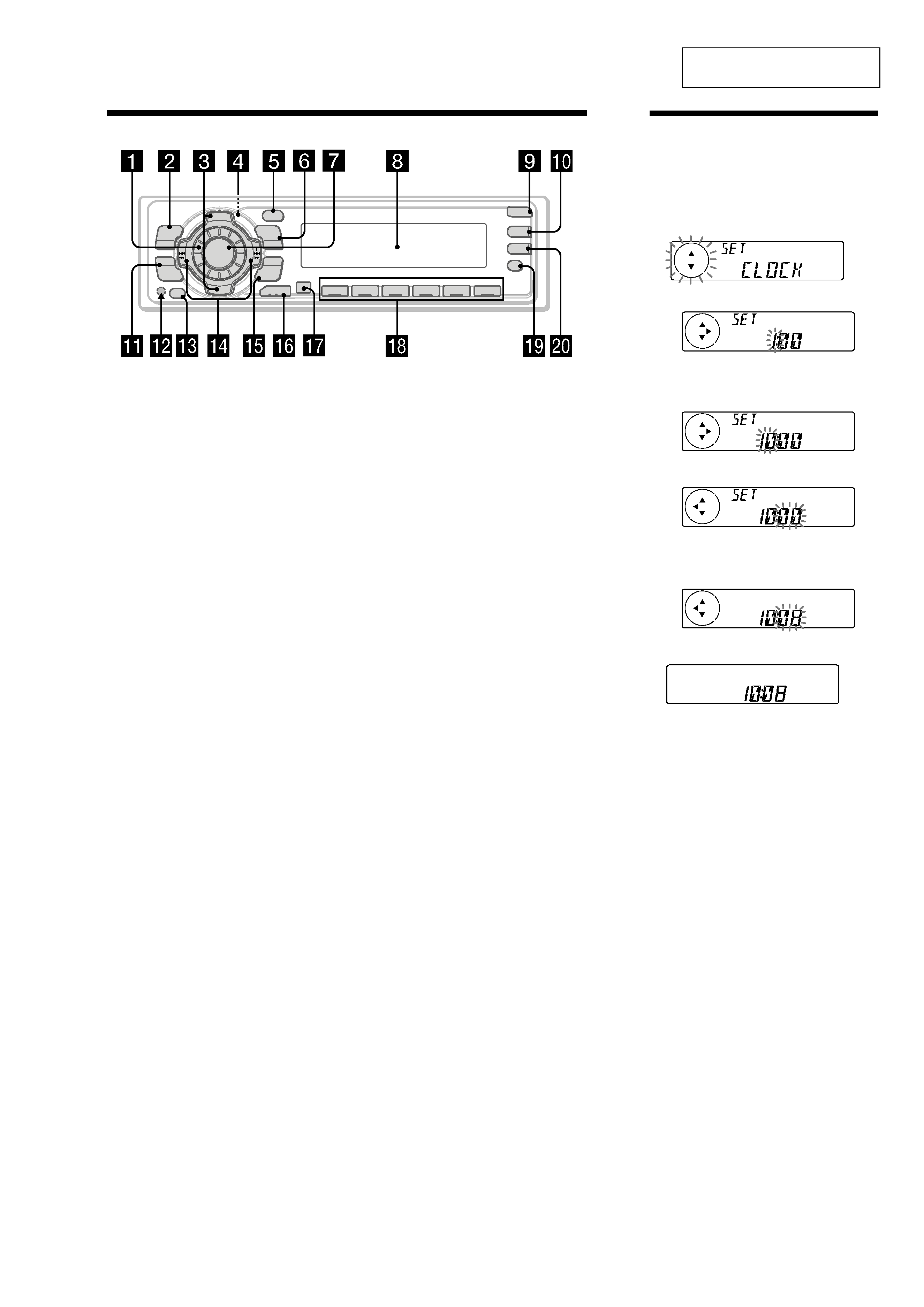
Location of controls
Refer to the pages listed for details.
1 Volume control dial 19
2 MENU button 8, 10, 12, 13, 14, 15, 16,
18, 19, 21, 24
3 DISC/PRST +/ (cursor up/down) buttons
8, 10, 12, 13, 14, 15, 16, 18, 19, 20, 21, 24
During CD/MD playback:
Disc change 10, 13
During radio reception:
Preset stations select 16
4 Z (eject) button (located on the front
side of the unit behind the front panel)
9
5 DSPL/PTY (display mode change/
programme type) button 9, 10, 12, 17,
20
6 LIST button 12
List-up 13
7 SOURCE (TUNER/CD/MD) button
8, 9, 10, 13, 15, 16, 19
8 Display window
9 OPEN button 7, 9, 26
q; D-BASS button 25
qa SOUND button 23
qs Reset button (located on the front side
of the unit behind the front panel) 7
qd OFF button* 7, 8, 9
qf SEEK/AMS /+ (cursor left/right) buttons
8, 10, 12, 14, 16, 18, 19, 21, 23, 24
Automatic Music Sensor 10, 14
Manual Search 10
Seek 15, 16, 18
qg ENTER button 8, 10, 12, 13, 14, 15, 16,
18, 19, 20, 21, 24
qh MODE button 19
During CD or MD playback:
CD/MD unit select 9, 13
During radio reception:
BAND select 15, 16
qj Receptor for the card remote
commander
qk Number buttons
During radio reception:
Preset number select 15, 16, 18, 19
During CD/MD playback:
(1) REP 11
(2) SHUF 11
ql AF button 17, 18, 19
w; TA button 18, 19
* Warning when installing in a car
without ACC (accessory) position on
the ignition key switch
Be sure to press (OFF) on the unit for two
seconds to turn off the clock display after
turning off the engine.
When you press (OFF) only momentarily,
the clock display does not turn off and this
causes battery wear.
D I SC +
PR
S
T+
-
D IS C
PR
ST- -
LIST
DSPL
AF
OFF
PTY
ENTER
MENU
SOUND
1
2
3
4
56
SOURCE
-SEEK/AMS
REP
SHUF
TA
OPEN
D-BASS
MODE
Setting the clock
The clock uses a 24-hour digital indication.
Example: To set the clock to 10:08
1 Press (MENU), then press either side of
(DISC/PRST) repeatedly until "CLOCK"
appears.
1
Press (ENTER).
The hour indication flashes.
2
Press either side of (DISC/PRST) to set
the hour.
3
Press the (+) side of (SEEK/AMS).
The minute indication flashes.
4
Press either side of (DISC/PRST) to set
the minute.
2 Press (ENTER).
The clock starts.
After the clock setting is completed, the
display returns to normal play mode.
Tip
You can set the clock automatically with the RDS
feature (see page 17).
Note
When the D.INFO mode is set to ON, the time is
always displayed, provided that the M.DSPL is set
to OFF (page 24).
4
2
4
1
3
Installation
Précautions
· Choisir soigneusement l'emplacement de
l'installation afin que l'appareil ne gêne
pas la conduite normale du véhicule.
· Eviter d'installer l'appareil dans un
endroit exposé à des températures
élevées, comme en plein soleil ou à
proximité d'une bouche d'air chaud, ou à
de la poussière, saleté ou vibrations
violentes.
· Pour garantir un montage sûr, n'utiliser
que le matériel fourni.
Réglage de l'angle de montage
Ajuster l'inclinaison à un angle inférieur à
20
°.
Installation
Vorsichtsmaßnahmen
· Wählen Sie den Einbauort sorgfältig so
aus, daß das Gerät beim Fahren nicht
hinderlich ist.
· Bauen Sie das Gerät so ein, daß es keinen
hohen Temperaturen (keinem direkten
Sonnenlicht, keiner Warmluft von der
Heizung), keinem Staub, keinem Schmutz
und keinen starken Vibrationen
ausgesetzt ist.
· Für eine sichere Befestigung verwenden
Sie stets nur die mitgelieferten
Montageteile.
Hinweis zum Montagewinkel
Das Gerät sollte in einem Winkel von
weniger als 20
° montiert werden.
Montage
Voorzorgsmaatregelen
· Kies de installatieplaats zorgvuldig zodat
het toestel de bestuurder niet hindert
tijdens het rijden.
· Installeer het apparaat niet op plaatsen
waar het blootgesteld wordt aan hoge
temperaturen, b.v. in direct zonlicht of bij
de warme luchtstroom van de
autoverwarming, aan sterke trillingen, of
waar het in contact komt met veel stof of
vuil.
· Gebruik voor het veilig en stevig
monteren van het apparaat uitsluitend de
bijgeleverde montage-onderdelen.
Maximale montagehoek
Installeer het apparaat nooit onder een hoek
van meer dan 20
° met het horizontale vlak.
Installazione
Precauzioni
· Scegliere con attenzione la posizione per
l'installazione in modo che l'apparecchio
non interferisca con le operazioni di
guida del conducente.
· Evitare di installare l'apparecchio dove
sia soggetto ad alte temperature, come
alla luce solare diretta o al getto di aria
calda dell'impianto di riscaldamento, o
dove possa essere soggetto a polvere,
sporco e vibrazioni eccessive.
· Usare solo il materiale di montaggio in
dotazione per un'installazione stabile e
sicura.
Regolazione dell'angolo di montaggio
Regolare l'angolo di montaggio in modo
che sia inferiore a 20
°.
Installation dans le tableau
de bord
Installation im
Armaturenbrett
Montage in het dashboard
Installazione nel cruscotto
1
2
3
Fire wall
Motorraumtrennwand
Paroi ignifuge
Parete frangifiamma
Brandschot
Dashboard
Armaturenbrett
Tableau de bord
Cruscotto
Dashboard
Bend these claws outward for a
tight fit, if necessary.
Falls erforderlich, diese Klammern
für einen sicheren Halt nach außen
biegen.
Plier ces griffes pour assurer une
prise correcte si nécessaire.
Piegare questi morsetti per
un`installazione più sicura, se
necessario.
Indien nodig kunt u deze lipjes
ombuigen voor een steviger
bevestiging.
1
A
Retrait et pose de la
façade
Avant d'installer l'appareil, déposer la
façade.
A Pour retirer
Avant de retirer la façade, ne pas oublier
d'appuyer d'abord sur (OFF). Appuyer
sur (OPEN), puis faire glisser la façade vers
la droite et la retirer par la gauche.
B Pour attacher
Fixez la partie
de la façade sur la partie
de l'appareil, comme indiqué sur
l'illustration, puis appuyez sur le côté
gauche jusqu'au déclic.
Abnehmen und Anbringen
der Frontplatte
Nehmen Sie die Frontplatte vor dem
Einbau des Geräts ab.
A Abnehmen
Drücken Sie auf jeden Fall (OFF), bevor Sie
die Frontplatte abnehmen. Drücken Sie
(OPEN), schieben Sie dann die Frontplatte
nach rechts, und ziehen Sie sie an der linken
Seite heraus.
B Anbringen
Setzen Sie die Aussparung
der
Frontplatte auf die Spindel
am Gerät auf,
wie in der Abbildung zu sehen, und
drücken Sie dann die linke Seite an.
Verwijderen en bevestigen
van het afneembare
voorpaneel
Verwijder, alvorens met het installeren
te beginnen, het afneembare
voorpaneel.
A Verwijderen
Druk eerst op (OFF) alvorens het
voorpaneel los te maken. Druk op (OPEN),
schuif het voorpaneel naar rechts en trek
het los aan de linkerkant.
B Bevestigen
Breng deel
van het voorpaneel aan op
deel
van het apparaat zoals afgebeeld en
druk op de linkerzijde tot deze vastklikt.
Come rimuovere e
reinserire il pannello
anteriore
Prima di installare l'apparecchio
rimuovere il pannello anteriore.
A Per rimuoverlo
Prima di rimuovere il pannello anteriore,
assicurarsi di premere (OFF). Premere
(OPEN), quindi far scivolare il pannello
anteriore verso destra e tirare il lato sinistro
verso di sé.
B Per reinserirlo
Applicare la foro
del pannello anteriore
al mandrino
dell'apparecchio come
mostrato nell'illustrazione e premere il lato
sinistro fino a sentire uno scatto.
B
c
4
1
2
5
7
7
5
5
7
Touche de réinitialisation
Quand l'installation et les connexions sont
terminées, appuyer sur la touche de
réinitialisation avec un stylo à bille, etc.
Rücksetztaste
Nach der Installation und dem Anschluß
muß die Rücksetztaste mit einem
Kugelschreiber o. ä. gedrückt werden.
Terugsteltoets
Druk, nadat u het apparaat heeft
geïnstalleerd en de aansluitingen heeft
gemaakt, met een balpen of een ander
puntig voorwerp op de terugsteltoets.
Tasto di azzeramento
Dopo avere terminato l'installazione e i
collegamenti, assicurarsi di premere il tasto
di azzeramento con la punta di una penna
a sfera o un oggetto simile.
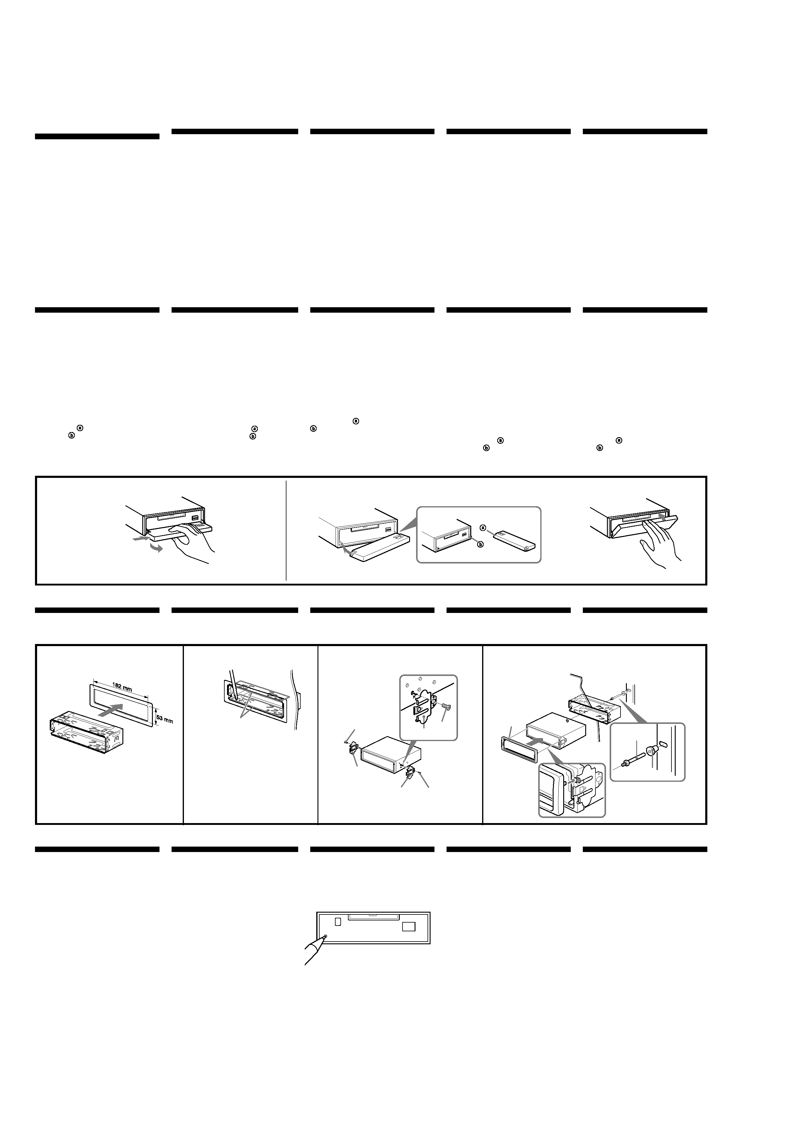
Installation
Precautions
· Choose the installation location carefully
so that the unit will not interfere with
normal driving operations.
· Avoid installing the unit in areas subject
to dust, dirt, excessive vibration, or high
temperature, such as in direct sunlight or
near heater ducts.
· Use only the supplied mounting
hardware for a safe and secure
installation.
Mounting angle adjustment
Adjust the mounting angle to less than 20
°.
How to detach and attach
the front panel
Before installing the unit, detach the
front panel.
A To detach
Before detaching the front panel, be sure to
press (OFF). Press (OPEN), then slide the
front panel to the right side, and pull out
the left side.
B To attach
Place the hole
in the front panel onto
the spindle
on the unit as illustrated,
then push the left side in.
Installation in the
dashboard
Reset button
When the installation and connections are
completed, be sure to press the reset button
with a ballpoint pen, etc.

5
Connexions
Précautions
· Cet appareil est conçu pour fonctionner
sur courant continu de 12 V avec masse
négative.
· Veiller à ne pas coincer de fils entre une
vis et la carrosserie de la voiture ou cet
appareil ou encore entre des pièces
mobiles comme les glissières des sièges,
etc.
· Brancher le cordon d'alimention 8 sur
l'appareil et les haut-parleurs avant de le
brancher sur le connecteur d'alimentation
auxiliaire.
· Rassembler tous les fils de terre en un
point de masse commun.
· Brancher le câble jaune à un circuit libre
de la voiture dont la capacité nominale
est supérieure à la capacité du fusible de
l'appareil. Si vous branchez cet appareil
en série avec d'autres composants stéréo,
le circuit de la voiture auquel ils sont
raccordés doit afficher une capacité
nominale supérieure à la somme des
capacités individuelles de chaque
composant. S'il n'y a pas de circuits de
voiture affichant une capacité égale à la
capacité du fusible de l'appareil, brancher
l'appareil directement à la batterie. Si
aucun circuit de voiture n'est disponible
pour connecter cet appareil, brancher
l'appareil à un circuit de voiture
supérieur à la capacité du fusible de
l'appareil de telle sorte que si l'appareil
grille son fusible, aucun autre circuit ne
soit coupé.
Anschluß
Vorsicht
· Dieses Gerät ist ausschließlich für den
Betrieb bei 12 V Gleichstrom (negative
Erdung) bestimmt.
· Achten Sie darauf, keine Kabel zwischen
einer Schraube und der Karosserie oder
diesem Gerät oder zwischen beweglichen
Teilen wie den Sitzschienen usw.
einzuklemmen.
· Verbinden Sie das Stromversorgungskabel
8
mit dem Gerät und den Lautsprechern,
bevor Sie es mit dem Hilfsstromanschluß
verbinden.
· Schließen Sie alle Erdungskabel an
einen gemeinsamen Massepunkt an.
· Schließen Sie das gelbe Kabel an einen
freien Autostromkreis mit höherer
Leistung als der der Gerätesicherung an.
Wenn Sie dieses Gerät zusammen mit
anderen Stereokomponenten anschließen,
muß der Autostromkreis, an den die
Geräte angeschlossen sind, eine höhere
Leistung aufweisen als die Summe der
Sicherungen der einzelnen Komponenten.
Wenn kein Autostromkreis eine so hohe
Leistung aufweist wie die Sicherung des
Geräts, schließen Sie das Gerät direkt an
die Batterie an. Wenn kein Autostromkreis
zum Anschließen dieses Geräts frei ist,
schließen Sie das Gerät an einen
Autostromkreis mit höherer Leistung als
der der Gerätesicherung an, und zwar so,
daß keine anderen Stromkreise
unterbrochen werden, wenn die
Sicherung durchbrennen sollte.
Aansluitingen
Let op!
· Dit apparaat is ontworpen voor gebruik
op gelijkstroom van een 12 Volts auto-
accu, negatief geaard.
· Zorg ervoor dat er geen snoeren geklemd
zitten tussen een schroef en het
koetswerk, het toestel of bewegende
onderdelen zoals de zetelrail, enz.
· Sluit het netsnoer 8 aan op het toestel en
de luidsprekers vooraleer u het op de
hulpvoedingsaansluiting aansluit.
· Sluit alle aarddraden op een
gemeenschappelijk aardpunt aan.
· Sluit het gele snoer aan op een vrij
autocircuit met een capaciteit die hoger
ligt dan die van de toestelzekering. Als u
dit toestel in serie schakelt met andere
audiocomponenten, moet de capaciteit
van het autocircuit waarop ze zijn
aangesloten hoger zijn dan de som van
de zekeringcapaciteit van elke
component afzonderlijk. Als er geen
autocircuits een even hoge capaciteit
hebben als de toestelzekering, moet het
toestel rechtstreeks worden aangesloten
op de accu. Als er geen autocircuits
beschikbaar zijn om dit toestel aan te
sluiten, moet u het toestel aansluiten op
een autocircuit met een hogere capaciteit
dan die van de toestelzekering. Indien de
toestelzekering dan doorbrandt, worden
geen andere circuits onderbroken.
Collegamenti
Attenzione
· Questo apparecchio è stato progettato per
l'uso solo a 12 V CC con massa negativa.
· Far attenzione che i cavi non rimangano
impigliati tra la vite e la carrozzeria della
macchina o l'apparecchio o tra le parti
mobili della macchina, come le guide di
scorrimento del sedile, ecc.
· Collegare il cavo di collegamento
dell'alimentazione 8 all'apparecchio e ai
diffusori prima di collegarlo al connettore
di alimentazione ausiliaria.
· Portare tutti i cavi di massa a un punto
di massa comune.
· Collegare il cavo giallo a un circuito
libero della macchina con potenza
nominale superiore a quella del fusibile
dell'apparecchio. Se si collega questo
apparecchio in serie con altri componenti
stereo, il circuito della macchina a cui
sono collegati deve avere una potenza
nominale superiore alla somma della
potenza nominale dei fusibili di ogni
componente. Se i circuiti della macchina
non hanno potenza nominale superiore a
quella dei fusibili, collegare l'apparecchio
direttamente alla batteria. Se non si
hanno a disposizione circuiti della
macchina per collegare l'apparecchio,
collegare l'apparecchio a un circuito della
macchina con potenza nominale
superiore a quella del fusibile
dell'apparecchio in modo tale che, se il
fusibile dell'apparecchio salta, gli altri
circuiti non verranno tagliati fuori.
Remarques sur l'exemple
de connexion
Remarques sur les fils de commande
et d'alimentation
· Le fil de commande (bleu) de l'antenne
électrique assure une alimentation de
+12 V CC lorsque vous mettez le
syntoniseur sous tension ou lorsque vous
activez la fonction AF (fréquence
secondaire) ou TA (informations
routières).
· Une antenne électrique sans boîtier de
relais ne peut pas être utilisée avec cet
appareil.
· Si votre voiture est équipée d'une
antenne FM/MW/LW intégrée dans la
vitre arrière/latérale, il est nécessaire de
raccorder le fil de commande de
l'antenne électrique (bleu) ou le fil
d'entrée d'alimentation des accessoires
(rouge) de l'amplificateur d'antenne
existant. Pour plus de détails, consultez
votre revendeur.
Avertissement
Si vous disposez d'une antenne électrique
sans boîtier de relais, le branchement de cet
appareil au moyen du cordon
d'alimentation fourni 8 risque
d'endommager l'antenne.
Connexion pour la conservation de la
mémoire
Lorsque le fil d'entrée d'alimentation jaune
est connecté, le circuit de la mémoire est
alimenté en permanence même si la clé de
contact est sur la position d'arrêt.
Remarques sur la connexion des haut-
parleurs
· Avant de raccorder les haut-parleurs,
mettre l'appareil hors tension.
· Utiliser des haut-parleurs ayant une
impédance de 4 à 8 ohms et une capacité
adéquate sous peine de les endommager.
· Ne pas raccorder les bornes du système
de haut-parleurs au châssis de la voiture
et ne pas connecter les bornes du haut-
parleur droit à celles du haut-parleur
gauche.
· Ne pas tenter de raccorder les haut-
parleurs en parallèle.
· Ne pas connecter d'enceintes acoustiques
actives (avec amplificateurs intégrés) aux
bornes d'enceinte de cet appareil, pour
éviter d'endommager les enceintes.
Veiller à raccorder des enceintes passives.
Avertissement en cas d'installation
dans une voiture dont le contact ne
comporte pas de position ACC
(accessoires)
Appuyez sur la touche (OFF) de
l'appareil pendant deux secondes pour
désactiver l'affichage de l'horloge
après avoir coupé le moteur.
Si vous n'appuyez que brièvement sur
(OFF), l'affichage de l'horloge ne
disparaît pas, ce qui provoque la
décharge de la batterie.
Hinweise zum
Anschlußbeispiel
Hinweise zu den Steuer- und
Stromversorgungsleitungen
· Die Motorantennen-Steuerleitung (blau)
liefert + 12 V Gleichstrom, wenn Sie den
Tuner einschalten oder die AF-
(Alternativfrequenzsuche) oder die TA-
Funktion (Verkehrsdurchsagen)
aktivieren.
· Es kann nur eine Motorantenne mit
Relaiskästchen angeschlossen werden.
· Wenn das Fahrzeug mit einer in der Heck-
/Seitenfensterscheibe integrierten UKW-/
MW/LW-Antenne ausgestattet ist,
müssen Sie die Motorantennen-
Steuerleitung (blau) oder die
Zubehörstromversorgungsleitung (rot) an
den Stromversorgungsanschluß des
vorhandenen Antennenverstärkers
anschließen. Näheres dazu erfahren Sie
bei Ihrem Händler.
Warnung
Wenn Sie eine Motorantenne ohne
Relaiskästchen verwenden, kann durch
Anschließen dieses Geräts mit dem
mitgelieferten Stromversorgungskabel 8
die Antenne beschädigt werden.
Stromversorgung des Speichers
Wenn das gelbe Stromversorgungskabel
angeschlossen ist, wird der Speicher stets
(auch bei ausgeschalteter Zündung) mit
Strom versorgt.
Hinweise zum Lautsprecheranschluß
· Schalten Sie das Gerät aus, bevor Sie die
Lautsprecher anschließen.
· Verwenden Sie Lautsprecher mit einer
Impedanz zwischen 4 und 8 Ohm und
ausreichender Belastbarkeit. Ansonsten
können die Lautsprecher beschädigt
werden.
· Verbinden Sie die Lautsprecheranschlüsse
nicht mit dem Wagenchassis, und
verbinden Sie auch nicht die Anschlüsse
des rechten mit denen des linken
Lautsprechers.
· Versuchen Sie nicht, Lautsprecher parallel
anzuschließen.
· An die Lautsprecheranschlüsse dieses
Geräts dürfen nur Passivlautsprecher
angeschlossen werden. Schließen Sie keine
Aktivlautsprecher (Lautsprecher mit
eingebauten Verstärkern) an, da diese
sonst beschädigt werden können.
Warnhinweis zur Installation des
Geräts in einem Auto mit Zündschloß
ohne Zubehörposition ACC oder I
Drücken Sie am Gerät unbedingt zwei
Sekunden lang (OFF), um die
Uhrzeitanzeige auszuschalten, nachdem
Sie den Motor ausgeschaltet haben.
Wenn Sie (OFF) nur kurz drücken, wird
die Uhrzeitanzeige nicht ausgeschaltet,
und der Autobatterie wird Strom
entzogen.
Opmerkingen bij
aansluitingsvoorbeeld
Opmerkingen betreffende de
voedingskabels en aansluitsnoeren
· De voedingskabel (blauw) van de
elektrisch bediende antenne levert +12V
gelijkstroom wanneer u de tuner
aanschakelt of de functie AF (Alternative
Frequency) of TA (Traffic
Announcement) activeert.
· Met dit apparaat is het niet mogelijk een
automatische antenne zonder relaishuis
te gebruiken.
· Indien uw auto is voorzien van een
ingebouwde FM/MW/LW-antenne in de
achter-/zijruit, moet de voedingskabel
van de elektrisch bediende antenne
(blauw) of de hulpvoedingskabel (rood)
worden aangesloten op de
voedingsaansluiting van de bestaande
antenneversterker. Raadpleeg uw dealer
voor meer details.
Opgelet
Indien u een elektrische antenne heeft
zonder relaiskast, kan het aansluiten van
deze eenheid met het bijgeleverde netsnoer
8
de antenne beschadigen.
Instandhouden van het geheugen
Zolang de gele stroomdraad is aangesloten,
blijft de stroomvoorziening van het
geheugen intact, ook wanneer het contact
van de auto wordt uitgeschakeld.
Opmerkingen betreffende het
aansluiten van de luidsprekers
· Zorg dat het apparaat is uitgeschakeld,
alvorens de luidsprekers aan te sluiten.
· Gebruik luidsprekers met een impedantie
van 4 tot 8 Ohm en let op dat die het
vermogen van de versterker kunnen
verwerken. Als dit wordt verzuimd,
kunnen de luidsprekers ernstig
beschadigd raken.
· Verbind in geen geval de aansluitingen
van de luidsprekers met het chassis van
de auto en sluit de aansluitingen van de
rechter en linker luidspreker niet op
elkaar aan.
· Probeer nooit de luidsprekers parallel
aan te sluiten.
· Sluit geen actieve luidsprekers (met
ingebouwde versterkers) aan op de
luidspreker-aansluitingen van dit
apparaat. Dit zal leiden tot beschadiging
van de actieve luidsprekers. Sluit dus
altijd uitsluitend luidsprekers zonder
ingebouwde versterker aan.
Opgelet bij het monteren in een
auto waarvan het contactslot geen
ACC (accessory) stand heeft
Druk (OFF) op het toestel gedurende
twee seconden in om de klokweergave
uit te schakelen na het afzetten van de
motor.
Indien u slechts even op (OFF) drukt,
verdwijnt de tijdindicatie niet waardoor
de batterij uitgeput raakt.
Note sui collegamenti
Note sui cavi di controllo e di
alimentazione
· Il cavo di controllo dell'antenna elettrica
(blu) fornisce corrente continua +12 V
quando si accende il sintonizzatore o
quando si attiva la funzione AF
(frequenza alternativa) o TA (notiziario
sul traffico).
· Non è possibile usare un'antenna
elettrica senza scatola a relè con questo
apparecchio.
· Se l'auto è dotata di un'antenna FM/MW
/LW incorporata nel vetro posteriore/
laterale, è necessario collegare il cavo di
controllo per l'antenna elettrica (blu) o il
cavo per l'ingresso dell'alimentazione
accessorio (rosso) al terminale di
alimentazione del preamplificatore
dell'antenna esistente. Per ulteriori
informazioni, consultare il proprio
rivenditore.
Avvertenza
Quando si collega l'apparecchio con il cavo
di alimentazione in dotazione 8, si
potrebbe danneggiare l'antenna elettrica se
questa non ha la scatola di relè.
Collegamento per la conservazione
della memoria
Quando il cavo di ingresso alimentazione
giallo è collegato, viene sempre fornita
alimentazione al circuito di memoria anche
quando la chiavetta a accensione è spenta.
Note sul collegamento dei diffusori
· Prima di collegare i diffusori spegnere
l'apparecchio.
· Usare diffusori di impedenza compresa
tra 4 e 8 ohm e con capacità di potenza
adeguata, altrimenti i diffusori
potrebbero venir danneggiati.
· Non collegare i terminali del sistema
diffusori al telaio dell'auto e non
collegare i terminali del diffusore destro a
quelli del diffusore sinistro.
· Non collegare i diffusori in parallelo.
· Non collegare alcun diffusore attivo (con
amplificatore incorporato) ai terminali
dei diffusori dell'apparecchio perché si
potrebbero danneggiare i diffusori attivi.
Assicurarsi di collegare i diffusori passivi
a questi terminali.
Informazioni importanti per quando
si effettua l'installazione su un'auto
sprovvista della posizione ACC
sull'interruttore di accensione
Assicurarsi di premere (OFF)
sull'apparecchio per due secondi per
spegnere il display dell'orologio dopo
che il motore è stato spento.
Se si preme (OFF) solo per un attimo, il
display dell'orologio non si spegne
causando in questo modo lo scaricamento
della batteria.
Connections
Cautions
· This unit is designed for negative ground
12 V DC operation only.
· Be careful not to pinch any wires between
the screw and the body of the car, or this
unit, or between any moving parts such
as the seat railing, etc.
· Connect the power connecting cord 8 to
the unit and speakers before connecting it
to the auxiliary power connector.
· Run all ground wires to a common
ground point.
· Connect the yellow cord to a free car
circuit rated higher than the unit's fuse
rating. If you connect this unit in
combination with other stereo
components, the car circuit they are
connected to must be rated higher than
the sum of the individual components'
fuse rating. If there are no car circuits
rated as high as the unit's fuse rating,
connect the unit directly to the battery. If
no car circuits are available for
connecting this unit, connect the unit to a
car circuit rated higher than the unit's
fuse rating in such a way that if the unit
blows its fuse, no other circuits will be
cut off.
Notes of connection
example
Notes on the control and power
supply leads
· The power aerial control lead (blue)
supplies +12 V DC when you turn on the
tuner or when you activate the AF
(Alternative Frequency), TA (Traffic
Announcement) function.
· A power aerial without a relay box
cannot be used with this unit.
· When your car has built-in FM/MW/LW
aerial in the rear/side glass, it is
necessary to connect the power aerial
control lead (blue) or the accessory power
input lead (red) to the power terminal of
the existing aerial booster. For details,
consult your dealer.
Warning
If you have a power aerial without a relay
box, connecting this unit with the supplied
power connecting cord 8 may damage the
aerial.
Memory hold connection
When the yellow power input lead is
connected, power will always be supplied
to the memory circuit even when the
ignition switch is turned off.
Notes on speaker connection
· Before connecting the speakers, turn the
unit off.
· Use speakers with an impedance of 4 to 8
ohms, and with adequate power
handling capacities. Otherwise, the
speakers may be damaged.
· Do not connect the terminals of the
speaker system to the car chassis, and do
not connect the terminals of the right
speaker with those of the left speaker.
· Do not attempt to connect the speakers in
parallel.
· Do not connect any active speakers (with
built-in amplifiers) to the speaker
terminals of the unit. Doing so may
damage the active speakers. Therefore, be
sure to connect passive speakers to these
terminals.
Warning when installing in a car
without ACC (accessory) position on
the ignition key switch
Be sure to press (OFF) on the unit for
two seconds to turn off the clock display
after turning off the engine.
When you press (OFF) only momentarily,
the clock display does not turn off and this
causes battery wear.