MICROFILM
SERVICE MANUAL
AEP Model
UK Model
Model Name Using Similar Mechanism
MDX-C7900R
Base Mechanism Type
MG-164KE-138
Optical Pick-Up Name
KMS-241B/J2N
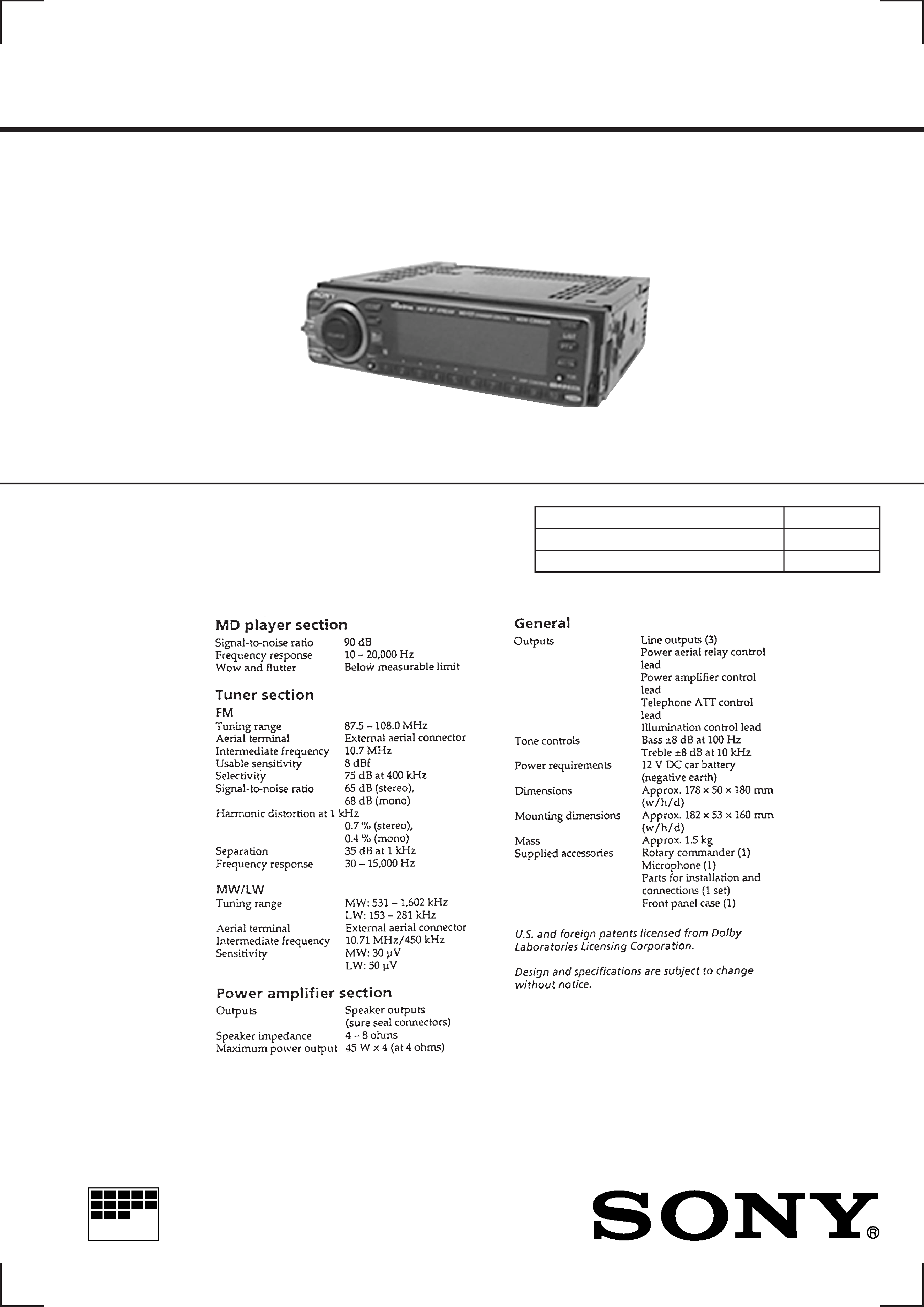
SPECIFICATIONS
MDX-C8900R
FM/MW/LW MINIDISC PLAYER
2
Notes on chip component replacement
· Never reuse a disconnected chip component.
· Notice that the minus side of a tantalum capacitor may be dam-
aged by heat.
Flexible Circuit Board Repairing
· Keep the temperature of the soldering iron around 270 °C dur-
ing repairing.
· Do not touch the soldering iron on the same conductor of the
circuit board (within 3 times).
· Be careful not to apply force on the conductor when soldering
or unsoldering.
NOTES ON HANDLING THE OPTICAL PICK-UP
BLOCK OR BASE UNIT
SAFETY-RELATED COMPONENT WARNING!!
COMPONENTS IDENTIFIED BY MARK
! OR DOTTED
LINE WITH MARK
! ON THE SCHEMATIC DIAGRAMS
AND IN THE PARTS LIST ARE CRITICAL TO SAFE
OPERATION. REPLACE THESE COMPONENTS WITH
SONY PARTS WHOSE PART NUMBERS APPEAR AS
SHOWN IN THIS MANUAL OR IN SUPPLEMENTS PUB-
LISHED BY SONY.
CAUTION
Use of controls or adjustments or performance of procedures
other than those specified herein may result in hazardous ra-
diation exposure.
The laser diode in the optical pick-up block may suffer electro-
static break-down because of the potential difference generated
by the charged electrostatic load, etc. on clothing and the human
body.
During repair, pay attention to electrostatic break-down and also
use the procedure in the printed matter which is included in the
repair parts.
The flexible board is easily damaged and should be handled with
care.
NOTES ON LASER DIODE EMISSION CHECK
Never look into the laser diode emission from right avove when
checking it for adustment. It is feared that you will lose your sight.
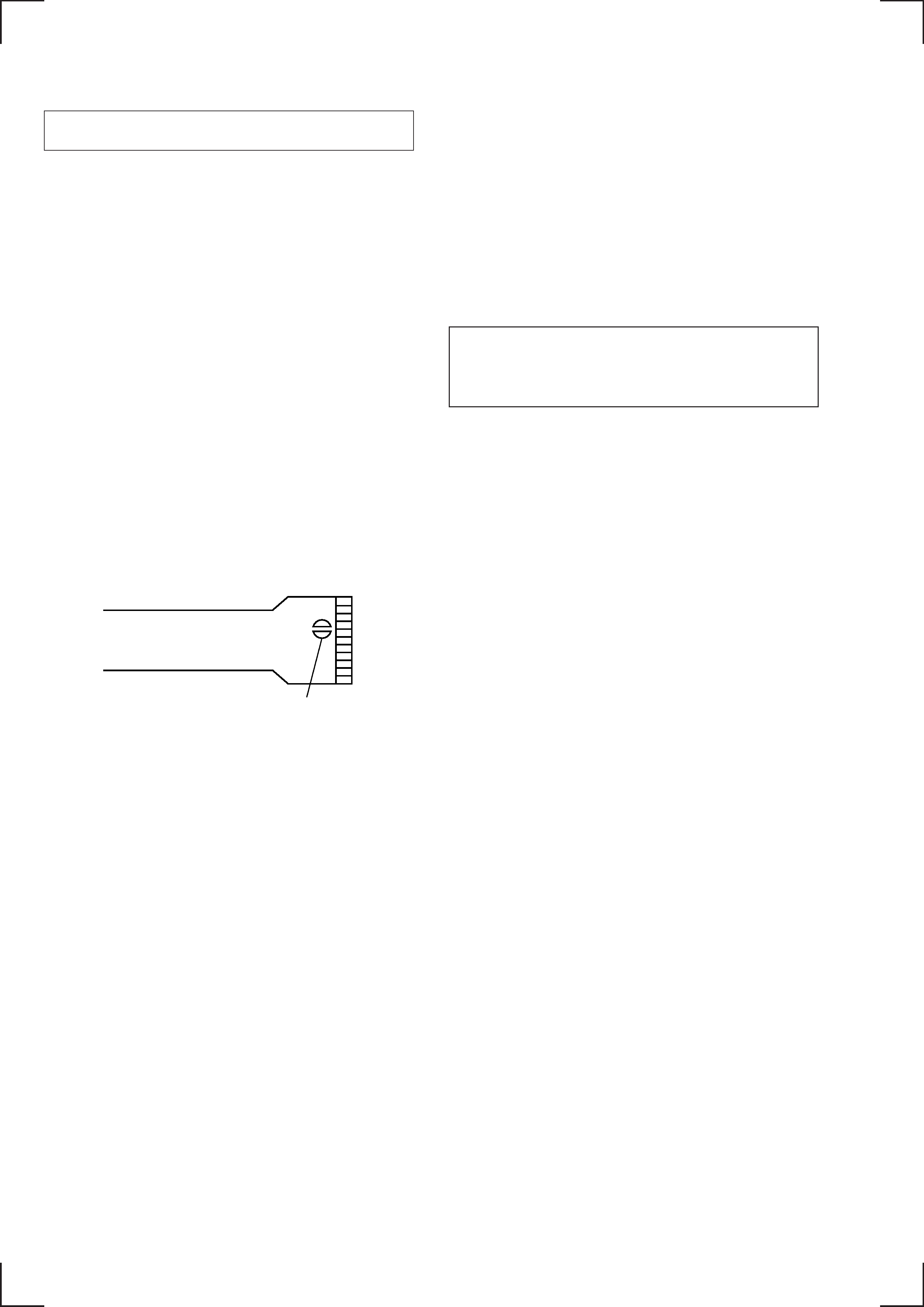
NOTES ON HANDLING THE OPTICAL PICK-UP BLOCK
(KMS-241B/J2N).
The laser diode in the optical pick-up block may suffer electro-
static break-down easily. When handling it, perform soldering
bridge to the laser-tap on the flexible board. Also perform m easures
against electrostatic break-down sufficiently before the operation.
The flexible board is easily damaged and should be handled with
care.
laser-tap
OPTICAL PICK-UP FLEXIBLE BOARD

3
1.
GENERAL
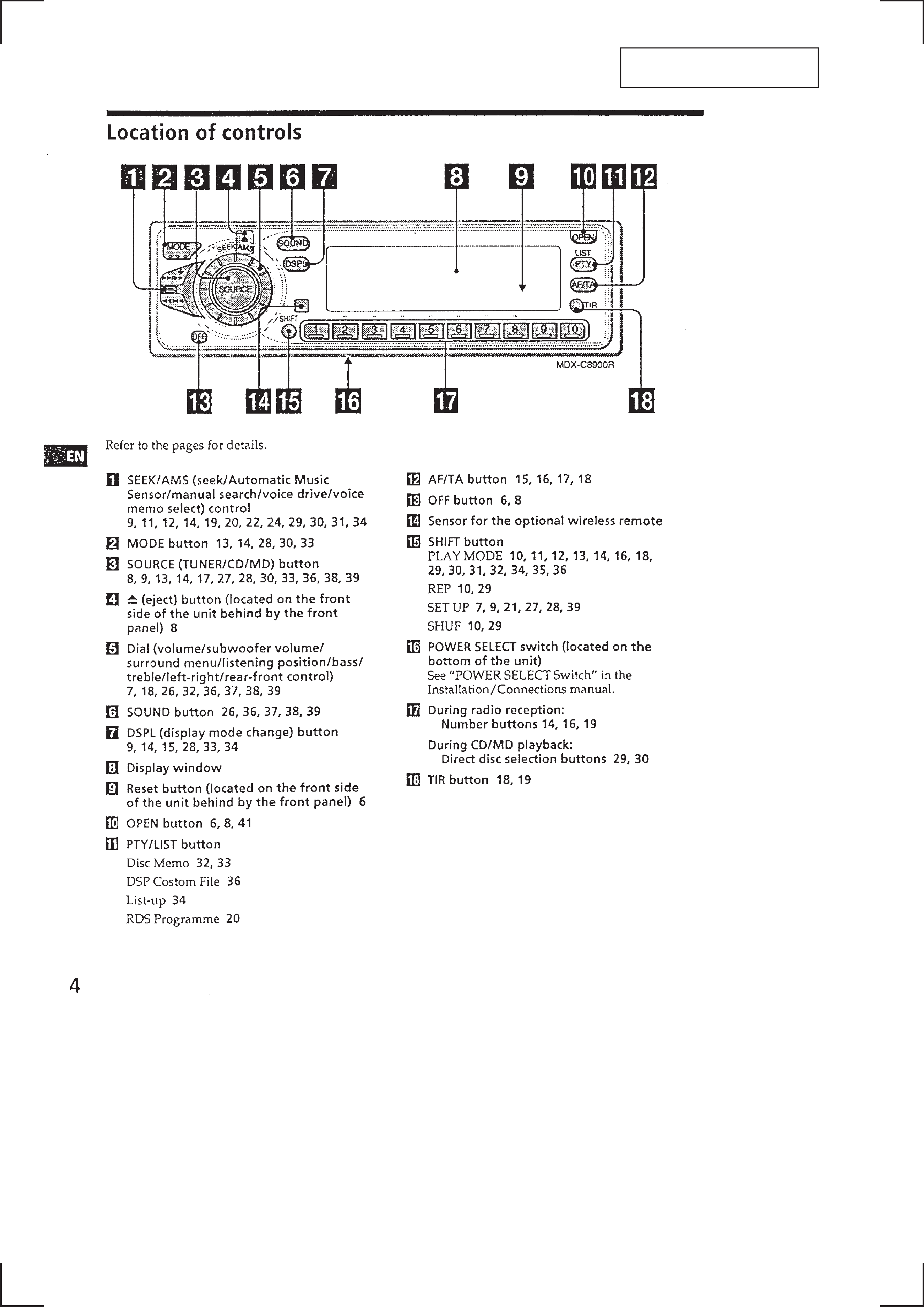
Location of Controls .......................................................
4
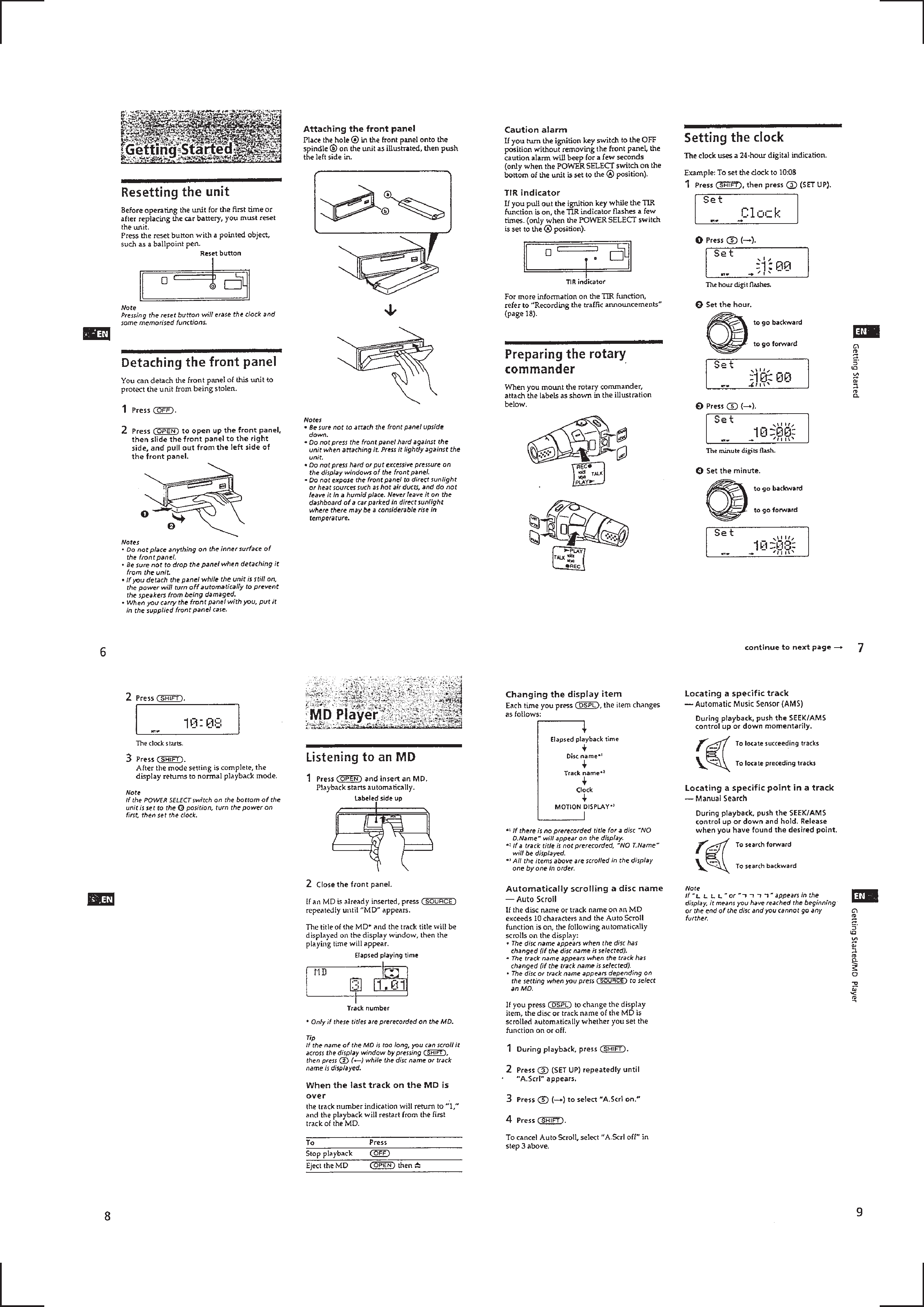
Resetting the Unit ...........................................................
5
Detaching the Front Panel ...............................................
5
Preparing the Rotary Commander ..................................
5
Setting the Clock .............................................................
5
Listening to an MD .........................................................
5
Playing an MD in Various Modes ...................................
6
Creating a Programme ....................................................
6
Memorising Stations Automatically ...............................
6
Memorising Only the Desired Stations ..........................
7
Receiving the Memorised Stations .................................
7
Overview of the RDS Function ......................................
7
Displaying the Station Name ..........................................
7
Re-Tuning the same Programme Automatically ............
7
Listening to Traffic Announcements ..............................
7
Presetting the RDS Stations with
the AF and TA Data .........................................................
8
Recording the Traffic Announcements ...........................
8
Locating a Station by Programme Type .........................
8
Setting the Clock Automatically .....................................
8
Selecting a "V Drive" Box for Registration ...................
8
Registering a Vocal Phrase ..............................................
9
Requesting a Registered Source .....................................
9
Recording a Voice Memo ................................................
9
Playing Back the Voice Memo ........................................
9
Erasing the Voice Memo .................................................
9
Using the Rotary commander .........................................
9
Adjusting the Sound Characteristics .............................. 10
Attenuating the Sound .................................................... 10
Changing the Sound and Display Settings ..................... 10
Adjusting the Frequency of the Subwoofer (s) .............. 10
Playing a CD or MD ....................................................... 10
Scanning the Tracks ........................................................ 10
Playing Tracks Repeatedly ............................................. 10
Playing Tracks in Random Order ................................... 10
Creating a Programme .................................................... 11
Labeling a CD ................................................................. 11
Locating a Disc by Name ................................................ 12
Selecting Specific Tracks for Playback .......................... 12
Selecting a Surround Menu ............................................ 12
Storing a Surround Effect onto CDs ............................... 12
Selecting the Listening Position ..................................... 12
Adjusting the Fader (FAD) ............................................. 13
Adjusting the Volume of the Subwoofer (s) ................... 13
Adjusting the Volume of the Bass and Treble ................ 13
Listening to Each Programme Source in Its Registered
Surround Menu ............................................................... 13
Changing the Line Output Level .................................... 13
Maintenance .................................................................... 13
Dismounting the Unit ...................................................... 13
Installation ....................................................................... 14
Connections ..................................................................... 17
2.
DISASSEMBLY ......................................................... 20
TABLE OF CONTENTS
3.
ELECTRICAL ADJUSTMENTS
Test Mode ........................................................................ 25
MD Section ..................................................................... 25
Tuner Section .................................................................. 25
4.
DIAGRAMS
4-1. Block Diagram SERVO Section ............................... 29
4-2. Block Diagram TUNER Section .............................. 31
4-3. Block Diagram MAIN Section ................................. 33
4-4. Block Diagram
DISPLAY/KEY CONTROL Section ........................ 35
4-5. Block Diagram BUS CONTROL/
POWER SUPPLY Section ........................................... 37
4-6. Notes for Printed Wiring Boards and
Schematic Diagrams ....................................................... 40
4-7. Printed Wiring Boards SERVO Section ................... 41
4-8. Schematic Diagram SERVO Section (1/3) ............... 43
4-9. Schematic Diagram SERVO Section (2/3) ............... 45
4-10. Schematic Diagram SERVO Section (3/3) ............... 47
4-11. Printed Wiring Board
MAIN Board (Component Side) .............................. 49
4-12. Printed Wiring Boards
MAIN Board (Conductor Side)/
SUPER CAPACITOR Board .................................... 51
4-13. Schematic Diagram MAIN Section (1/4) ................. 53
4-14. Schematic Diagram MAIN Section (2/4) ................. 55
4-15. Schematic Diagram MAIN Section (3/4) ................. 57
4-16. Schematic Diagram MAIN Section (4/4) ................. 59
4-17. Printed Wiring Board AUDIO Section ..................... 61
4-18. Schematic Diagram AUDIO Section ........................ 63
4-19. Printed Wiring Board PANEL Section ..................... 65
4-20. Schematic Diagram PANEL Section ........................ 67
4-21. Printed Wiring Board RELAY Section ..................... 69
4-22. Schematic Diagram RELAY Section ....................... 71
4-23. IC Pin Function Description ........................................... 81
5.
EXPLODED VIEWS ................................................ 91
6.
ELECTRICAL PARTS LIST ............................... 95
4
SECTION 1
GENERAL
This section is extracted from
instruction manual.
5