1
MDS-SP55
SPECIFICATIONS
SERVICE MANUAL
MINIDISC DECK
Model Name Using Similar Mechanism
MDS-JE330
MD Mechanism Type
MDM-5A
Optical Pick-up Type
KMS-260B/S1NP
AEP Model
UK Model
E Model
System
MiniDisc digital audio system
Laser
Semiconductor laser (
=780 nm)
Emission duration: continuous
Laser output
Max. 44.6 µW*
*This output is the value
measured at a distance of 200 mm
from the objective lens surface on
the Optical Pick-up Block with
7 mm aperture.
Sampling frequency
44.1 kHz
Frequency response
20 Hz 20 kHz
Inputs
DIGITAL OPTICAL CD IN: Optical
DIGITAL OPTICAL AUX IN: Optical
Output
DIGITAL OPTICAL OUT:
Optical
General
Dimensions (w/h/d) incl. projecting parts and controls
Approx. 202
× 101 × 298 mm
Mass
Approx. 1.7 kg
Supplied accessories
System cable (1)
Digital cable (1)
Design and specifications are subject to change
without notice.
MDS-SP55 is the MD section in CMT-SP55MD,
and MDS-SP55 is sold in the option as a
minidisk deck of CMT-SP55TC.
2
SELF-DIAGNOSIS FUNCTION
The self-diagnosis function consists of error codes for customers which are displayed automatically when errors occur, and error codes which
show the error history in the test mode during servicing. For details on how to view error codes for the customer, refer to the following box
in the instruction manual. For details on how to check error codes during servicing, refer to the following "Procedure for using the Self-
Diagnosis Function (Error History Display Mode)".
Procedure for using the Self-Diagnosis Function (Error History Display Mode).
Note: Perform the self-diagnosis function in the "error history display mode" in the test mode. The following describes the least required
procedure. Be careful not to enter other modes by mistake. If you set other modes accidentally, press the MENU/NO button (MD)
to exit the mode.
1. When the power OFF (STANDBY), press the ?/1 button (TA) while pressing the s button (MD) and ENTER/YES button (MD)
together.
2. Press the MENU/NO button, and when "Check" is displayed.
3. Rotate the l L knob (MD) and when "[Service]" is displayed, press the ENTER/YES button (MD).
4. Rotate the l L knob (MD) and display "ERR DP MODE".
5. Pressing the ENTER/YES button (MD) sets the error history mode and displays "total rec".
6. Select the contents to be displayed or executed using the l L knob (MD).
7. Pressing the CD SYNC REC button (MD) and to execute the contents selected.
8. Pressing the CD SYNC REC button (MD) another time returns to step 5.
9. Pressing the MENU/NO button (MD) displays "ERROR DP MODE" and exits the error history mode.
10.To exit the test mode, press the ?/1 button (TA). The unit sets into the STANDBY state, the disc is ejected, and the test mode ends.
Self-diagnosis Display
This system has a Self-diagnosis display function
to let you know if there is a system malfunction.
The display shows a code made up of three letters
and a message alternately to show you the
problem. To solve the problem refer to the
following list. If any problem persists, consult
your nearest Sony dealer.
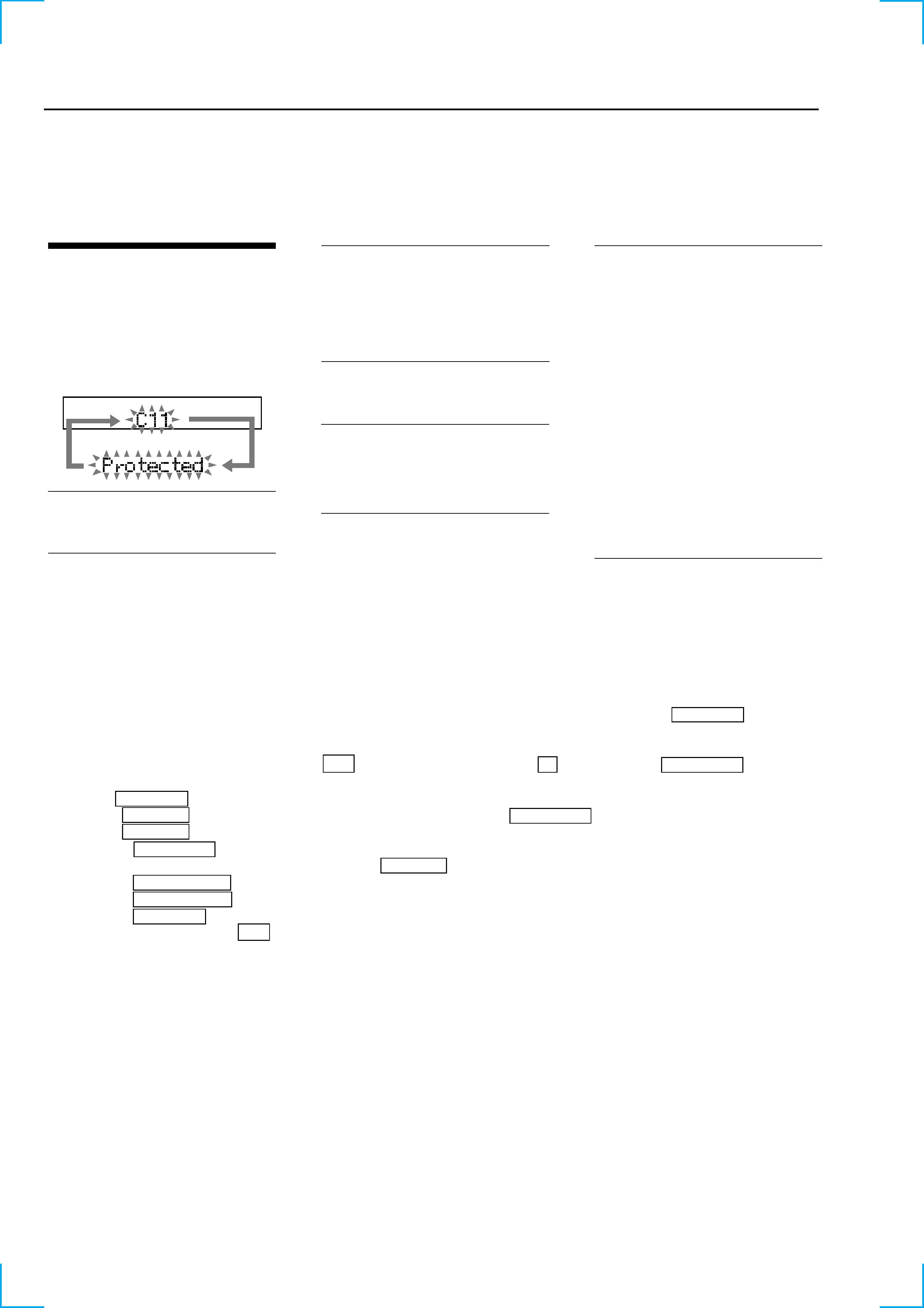
C11/Protected
The MD is protected against erasure.
cRemove the MD and slide the tab to close the
slot (See page 11).
C12/Cannot Copy
You tried to record a CD or MD with a format
that the system does not support, such as a CD-
ROM.
cRemove the disc and turn off the system once,
then turn it on again.
C13/REC Error
Recording could not be performed properly.
cMove the system to a stable place, and start
recording over from the beginning.
The MD is dirty or scratched, or the MD does
not meet the standards.
cReplace the MD and start recording over from
the beginning.
C13/Read Error
The MD deck cannot read the disc information
properly.
cRemove the MD once, then insert it again.
C14/Toc Error
The MD deck cannot read the disc information
properly.
cReplace the MD.
cErase all the recorded contents of the MD
using the All Erase function (See page 32).
C41/Cannot Copy
The sound source is a copy of a commercially
available music software, or you tried to record
a CD-R (Recordable CD).
cThe Serial Copy Management System
prevents making a digital copy.
You cannot record a CD-R (see page 43).
C71/Check OPT-IN
This appears momentarily because of the signal
of the digital broadcast during recording.
cThere is no affect on the recorded contents.
No component is connected to the DIGITAL
OPTICAL IN jack, or a digital component is
not connected properly.
cConnect a digital component to the DIGITAL
OPTICAL IN jack properly using a digital
connecting cable (an optical cable) (not
supplied (See page 39).
The connected digital component is not turned
on.
cSee the operating instructions supplied with
the connected component and confirm
whether the component is turned on.
The digital connecting cable (an optical cable)
connected to the DIGITAL OPTICAL IN jack
is pulled out, or the connected digital
component is turned off during digital
recording.
cConnect the cable, or turn on the digital
component.
3
Displays the recording time.
Displayed as "rssssssh".
The displayed time is the total time the laser is set to the high power state.
This is about 1/4 of the actual recording time.
The time is displayed in decimal digits from 0h to 65535h.
Displays the play time.
Displayed as "pssssssh". The time displayed is the total actual play time. Pauses are not counted.
The time is displayed in decimal digits from 0h to 65535h.
Displays the total number of retries during recording and number of retry errors during play.
Displayed as "rss pss".
"r" indicates the retries during recording while "p" indicates the retry errors during play.
The number of retries and retry errors are displayed in hexadecimal digits from 00 to FF.
Displays the total number of errors.
Displayed as "total ss".
The number of errors is displayed in hexadecimal digits from 00 to FF.
Displays the 10 latest errors.
Displayed as "0s E@@".
s indicates the history number. The smaller the number, the more recent is the error. (00 is the latest).
@@ indicates the error code.
Refer to the following table for the details. The error history can be switched by rotating the l L knob (MD).
Mode which erases the "retry err", "total err", and "err history" histories.
When returning the unit to the customer after completing repairs, perform this to erase the past error history,
After pressing the CD SYNC REC button (MD) when "er refresh" appears, press ENTER/YES button (MD) to
erase the history.
"Complete!!" will be displayed momentarily.
Be sure to check the following when this mode has been executed.
· The data has been erased.
· The mechanism operates normally when recording and play are performed.
Mode which erases the "total rec" and "total play" histories.
These histories serve as approximate indications of when to replace the optical pick-up.
If the optical pick-up has been replaced, perform this operation and erase the history.
After pressing the CD SYNC REC button (MD) when "tm refresh?" is displayed, press the ENTER/YES button
(MD) to erase the history.
"Complete!" will be displayed momentarily.
Be sure to check the following when this mode has been executed.
· The data has been erased.
· The mechanism operates normally when recording and play are performed.
ITEMS OF ERROR HISTORY MODE ITEMS AND CONTENTS
Selecting the Test Mode
Display
total rec
total play
retry err
total err
err history
er refresh
tm refresh?
Details of History
No error
Read error. PTOC cannot be read
(DISC ejected)
TOC error. UTOC error
(DISC not ejected)
Loading error
Address cannot be read (Servo has deviated)
Table of Error Codes
Error Code
E00
E01
E02
E03
E04
E05
E06
E07
E08
E09
E0A
FOK has deviated
Cannot focus (Servo has deviated)
Recording retry
Recording retry error
Playback retry error
(Access error)
Play retry error (C2 error)
Details of Error
Error Code
Details of Error
4
CAUTION
Use of controls or adjustments or performance of procedures
other than those specified herein may result in hazardous ra-
diation exposure.
Notes on chip component replacement
· Never reuse a disconnected chip component.
· Notice that the minus side of a tantalum capacitor may be
damaged by heat.
Flexible Circuit Board Repairing
· Keep the temperature of soldering iron around 270°C
during repairing.
· Do not touch the soldering iron on the same conductor of the
circuit board (within 3 times).
· Be careful not to apply force on the conductor when soldering
or unsoldering.
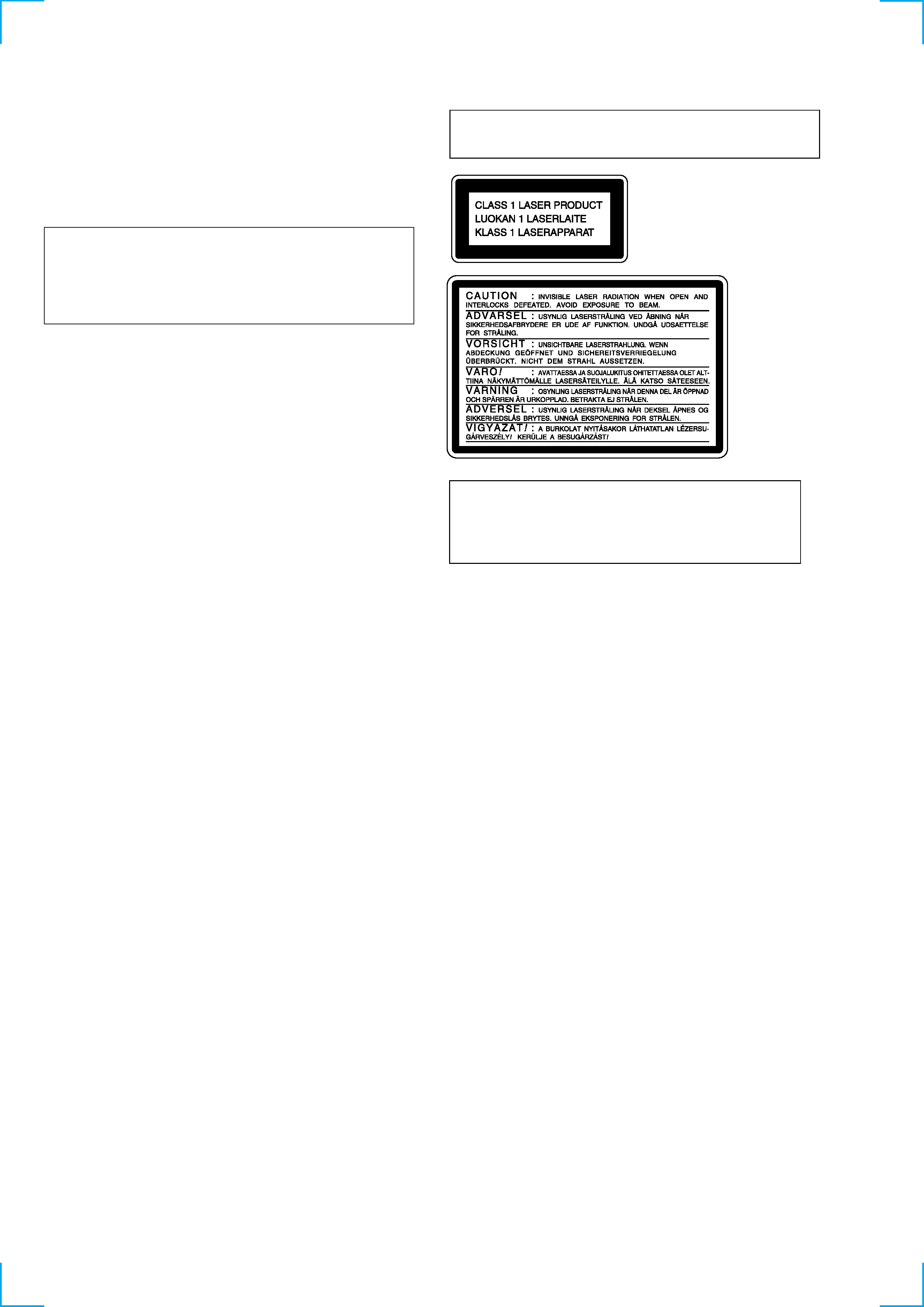
Laser component in this product is capable of emitting radiation
exceeding the limit for Class 1.
This appliance is classified as
a CLASS 1 LASER product.
The CLASS 1 LASER PROD-
UCT MARKING is located on
the rear exterior.
This caution
label is located
inside the unit.
CAUTION
Danger of explosion if battery is incorrectly replaced.
Replace only with the same or equivalent type recommended by
the equipment manufacturer.
Discard used batteries according to manufacture's instructions.
ADVARSEL!
Lithiumbatteri - Eksplosionsfare ved fejlagtig håndtering.
Udskiftning må kun ske med batteri af samme fabrikat og type.
Levér det brugte batteri tilbage til leverandøren.
ADVARSEL
Eksplosjonsfare ved feilakting skifte av batteri.
Benytt samme batteritype eller en tilsvarende type anbefalt av
apparatfabrikanten.
Brukte batterier katterier kasseres i henhold til fabrikantens
VARNIG
Explosionsfara vid felaktigt batteribyte.
Använd samma batterityp eller en likvärdig typ som rekommenderas
av apparattillverkaren.
Kassera använt batteri enligt gällande föreakrifter.
VAROITUS
Parist voi räjähtää, jos se on virheellisesti asennettu.
Vaihda paristo ainoastaan laitevalmistajan suosittelemaan tyyppiin.
Hävitä käytetty paristo valmistajan ohjeiden mukaisesti.
SAFETY-RELATED COMPONENT WARNING !!
COMPONENTS IDENTIFIED BY MARK 0 OR DOTTED LINE
WITH MARK 0 ON THE SCHEMATIC DIAGRAMS AND IN
THE PARTS LIST ARE CRITICAL TO SAFE OPERATION.
REPLACE THESE COMPONENTS WITH SONY PARTS
WHOSE PART NUMBERS APPEAR AS SHOWN IN THIS
MANUAL OR IN SUPPLEMENTS PUBLISHED BY SONY.

5
TABLE OF CONTENTS
1. SERVICING NOTE .......................................................... 6
2. GENERAL ........................................................................ 13
3. DISASSEMBLY
3-1. Case ..................................................................................... 14
3-2. Front Panel Assy ................................................................. 14
3-3. MD Mechanism Deck (MDM-5A) ..................................... 15
3-4. Main Board ......................................................................... 15
3-5. Slider (Cam) ........................................................................ 16
3-6. BD Board ............................................................................ 16
3-7. Over Write Head ................................................................. 17
3-8. Optical Pick-up (KMS-260A/J1N) ..................................... 17
3-9. Spindle Motor, Sled Motor ................................................. 17
4. TEST MODE ..................................................................... 18
5. ELECTRICAL ADJUSTMENTS ............................... 22
6. DIAGRAMS
6-1. Block Diagrams
· BD Section ....................................................................... 32
· Main Section .................................................................... 33
6-2. Printed Wiring Board BD Section ................................. 34
6-3. Schematic Diagram BD (1/2) Section ........................... 35
6-4. Schematic Diagram BD (2/2) Section ........................... 36
6-5. Schematic Diagram Main (1/2) Section ........................ 37
6-6. Schematic Diagram Main (2/2) Section ........................ 38
6-7. Printed Wiring Board Main Section .............................. 39
6-8. Printed Wiring Board Panel Section ............................. 40
6-9. Schematic Diagram Panel Section ................................ 41
6-10. Schematic Diagram BD Switch Section .................... 42
6-11. Printed Wiring Board BD Switch Section .................. 42
6-12. IC Block Diagrams ........................................................... 42
6-13. IC Pin Functions ............................................................... 45
7. EXPLODED VIEWS
7-1. Case and Front Panel Section ............................................. 50
7-2. Mechanism Deck Section (MDM-5A) ................................ 51
7-3. Base Unit Section (MBU-5A) ............................................. 52
8. ELECTRICAL PARTS LIST ........................................ 53
MODEL IDENTIFICATION
-- BACK PANEL --
· Abbreviation
AED
: North European model
MY
: Malaysia model
SP
: Singapore model
HK
: Hong kong model
KR
: Korea model
MODEL
AEP, UK, AED models
HK, MY, SP models
KR model
PARTS No.
4-229-665-0s
4-229-665-2s
4-229-665-3s
Parts No.