SERVICE MANUAL
Ver 1.0 2001.06
MINIDISC DECK
AEP Model
UK Model
SPECIFICATIONS
MDS-S9
Model Name Using Similar Mechanism
MDS-S50
MD Mechanism Type
MDM-7A
Optical Pick-up Name
KMS-260B
System
MiniDisc digital audio
system
Disc
MiniDisc
Laser
Semiconductor laser (
=
780 nm) Emission
duration: continuous
Laser output
MAX 44.6
µW1)
1)
This output is the value measured at a distance of
200 mm from the objective lens surface on the
Optical Pick-up Block with 7 mm aperture.
Laser diode
Material: GaAlAs
Revolutions (CLV)
400 rpm to 900 rpm
Error correction
ACIRC (Advanced Cross
Interleave Reed Solomon
Code)
Sampling frequency
44.1 kHz
Coding
ATRAC (Adaptive
TRansform Acoustic
Coding)/ATRAC 3
Modulation system
EFM (Eight-to-Fourteen
Modulation)
Number of channels
2 stereo channels
Frequency response
5 to 20,000 Hz
±0.3 dB
Signal-to-noise ratio
Over 96 dB during play
Wow and flutter
Below measurable limit
Inputs
ANALOG IN
Jack type: phono
Impedance: 47 kilohms
Rated input: 500 mVrms
Minimum input:
125 mVrms
DIGITAL IN
Connector type: square
optical
Impedance: 660 nm
(optical wave length)
Outputs
ANALOG OUT
Jack type: phono
Rated output: 2 Vrms (at
50 kilohms)
Load impedance: over 10
kilohms
General
Power requirements
230 V AC, 50/60Hz
Power consumption
15 W
0.5 W (at the STANDBY
mode)
Dimensions (approx.)
280
× 83 × 290 mm (w/
h/d) incl. projecting parts
and controls
Mass (approx.)
2.4 kg
Supplied accessories
Audio connecting cords (2)
Optical cable (1)
Remote commander (remote) (1)
R6 (size-AA) batteries (2)
Design and specifications are subject to change
without notice.
US and foreign patents licensed from Dolby
Laboratories.
9-873-914-11
Sony Corporation
2001F0500-1
Home Audio Company
C
2001.6
Shinagawa Tec Service Manual Production Group

2
MDS-S9
PROCEDURE FOR USING THE SELF-DIAGNOSIS FUNCTION (ERROR HISTORY DISPLAY MODE)
Note: Perform the self-diagnosis function in the "error history display mode" in the test mode. The following describes the least required procedure. Be
careful not to enter other modes by mistake. If you set other modes accidentally, press the MENU/NO button to release the mode.
1. While pressing the [
AMS
] knob and x button simultaneously, connect the power plug to the outlet, and release the
[
AMS
] knob and x button simultaneously to display "[Check]".
2. Turn the [
AMS
] knob and when "[Service]" is displayed, press the [YES] button to display "AUTO CHECK" (C01).
3. Turn the [
AMS
] knob to display "Err Display" (C02).
4. Press the [YES] button to sets the error history mode and displays "op rec tm".
5. Select the contents to be displayed or executed using the [
AMS
] knob.
6. Press the [
AMS
] knob to display or execute the contents selected.
7. Press the [
AMS
] knob another time returns to step 4.
8. Press the [MENU/NO] button to display "Err Display" (C02) and release the error history mode.
9. To release the test mode, press the I/1 button. The unit sets into the STANDBY state, and the test mode ends.
SELF-DIAGNOSIS FUNCTION
The deck's self-diagnosis function
automatically checks the condition of the MD
deck when an error occurs, then issues a three-
or five-digit code and an error message on the
display. If the code and message alternate, find
them in the following table and perform the
indicated countermeasure. Should the problem
persist, consult your nearest Sony dealer.
C11/Protected
, Take out the MD and close the record-protect
slot.
C12/Cannot Copy
· You tried to record a CD with a format that the
external device connected to the deck does not
support, such as CD-ROM or video CD.
, Remove the disc and insert a music CD.
C13/REC Error
, Set the deck in a stable surface, and repeat the
recording procedure.
· The inserted MD is dirty (with smudges,
fingerprints, etc.), scratched, or substandard in
quality.
, Replace the disc and repeat the recording
procedure.
C13/Read Error
, Take out the MD and insert it again.
C14/TOC Error
, Insert another disc.
, If possible, erase all the tracks on the MD.
C41/Cannot Copy
· The sound source is a copy of commercially
available music software, or you tried to record a
CD-R (Recordable CD).
, The Serial Copy Management System
prevents making a digital copy. You cannot
record a CD-R.
C71/Din Unlock
· The sporadic appearance of this message is
caused by the digital signal being recorded. This
will not affect the recording.
· While recording from a digital component
connected through the DIGITAL IN connector,
the digital connecting cable was unplugged or the
digital component turned off.
, Connect the cable or turn the digital
component back on.
.
>
.
>
.
>
.
>
.
>
.
>
.
>
3
MDS-S9
ITEMS OF ERROR HISTORY MODE ITEMS AND CONTENTS
Display
Details of History
op rec tm
Cumulative recording time is displayed.
When cumulative recording time is over 1 minute, the hour and minute are displayed as they are.
When it is under 1 minute, "Under 1 min" is displayed.
The displayed time is the total time the laser is set to the high power state.
This is about 1/4 of the actual recording time. The time is displayed in decimal digits.
op play tm
Cumulative playing time is displayed.
When cumulative playing time is over 1 minute, the hour and minute are displayed as they are.
When it is under 1 minute, "Under 1 min" is displayed.
The displayed time is the total of the actual play time. Pauses are not counted.
The time is displayed in decimal digits.
spdl rp tm
Cumulative spindle motor running time is displayed.
When cumulative spindle motor run time is over 1 minute, the hour and minute are displayed as they are.
When it is under 1 minute, "Under 1 min" is displayed.
The time is displayed in decimal digits.
retry err
Displays the total number of retries during recording and number of retry errors during playback.
Displayed as "r ss p ss".
"r" indicates the retries during recording while "p" indicates the retry errors during playback.
The number of retries and retry errors are displayed in hexadecimal digits from 00 to FF.
total err
Displays the total number of errors.
Displayed as "total ss".
The number of errors is displayed in hexadecimal digits from 00 to FF.
err history
Displays the 10 latest errors.
Displayed as "0s ErrCd @@".
s indicates the history number. The smaller the number, the more recent is the error. (00 is the latest)
@@ indicates the error code.
Refer to the following table for the details. The error history can be switched by turning the [
AMS
]
knob.
retry adrs
Display the 5 latest retry address.
Display as "ss ADRS@@@@".
ss indicates the history number. The smaller the number, the more recent is the error. (00 is the latest)
@@@@ indicates the cluster of retry address.
The number of retry address can be switched by turning the [
AMS
] knob.
er refresh
Mode to clear the error history and retry address history.
Procedure:
1) Press the [
AMS
] button.
2) The display will change to "er refresh?", and then press the [YES] button.
The operation is over if "Complete!" is displayed.
After this mode was executed, check the following:
· The data have been cleared.
· Perform the recording and playing to check that the mechanism operates normally.
op change
Mode to clear cumulative time of "op rec tm" and "op play tm".
These historical data are used to determine the timing when the optical pick-up is to be replaced. When the
optical pick-up was replaced, perform this operation to clear historical data.
Procedure:
1) Press the [
AMS
] button.
2) The display will change to "op chang?", and then press the [YES] button.
The operation is over if "Complete!" is displayed.
spdl change
Mode to clear cumulative time of "spdl rp tm".
This historical data is used to determine the timing when the spindle motor is to be replaced. When the spindle
motor was replaced, perform this operation to clear historical data.
Procedure:
1) Press the [
AMS
] button.
2) The display will change to "spdl chang?", and then press the [YES] button.
The operation is over if "Complete!" is displayed.
.
>
.
>
.
>
.
>
.
>
4
MDS-S9
Error Code
Details of Error
10
Loading failed
12
Loading switch combination is illegal
20
Head of PTOC could not be read within the
specified time
21
Head of PTOC could be read but its content is
erroneous
22
Access to UTOC could not be made within the
specified time
23
UTOC could be not read within the specified
time
24
Content of UTOC is erroneous
30
Playing could not start
31
Content of sector is erroneous
40
Cause of retry occurred during normal recording
41
D-RAM overflowed and retry was executed
42
Retry was executed during the writing to TOC
43
S.F editing was interrupted by retry
50
Address could not be read except in access
processing
51
Focusing failed and it is out of control
60
Unlock retry
Table of Error Codes
5
MDS-S9
TABLE OF CONTENTS
SELF-DIAGNOSIS FUNCTION .................................... 2
1.
SERVICING NOTES ............................................... 6
2.
GENERAL ................................................................... 10
3.
DISASSEMBLY
3-1. Disassembly Flow ........................................................... 12
3-2. Case ................................................................................. 13
3-3. MD Mechanism Deck (MDM-7A) ................................. 13
3-4. MAIN Board ................................................................... 14
3-5. BD Board ......................................................................... 14
4.
TEST MODE .............................................................. 15
5.
ELECTRICAL ADJUSTMENTS ......................... 20
6.
DIAGRAMS
6-1. Block Diagram SERVO Section ............................... 31
6-2. Block Diagram MAIN Section ................................. 32
6-3. Note for Printed Wiring Boards and
Schematic Diagrams ....................................................... 33
6-4. Printed Wiring Boards BD Board ............................. 35
6-5. Schematic Diagram BD Board (1/2) ........................ 36
6-6. Schematic Diagram BD Board (2/2) ........................ 37
6-7. Printed Wiring Board
MAIN Board (Component Side) .............................. 38
6-8. Printed Wiring Board
MAIN Board (Conductor Side) ................................ 39
6-9. Schematic Diagram MAIN Board (1/3) ................... 40
6-10. Schematic Diagram MAIN Board (2/3) ................... 41
6-11. Schematic Diagram MAIN (3/3)/PT Boards ............ 42
6-12. Printed Wiring Board PT Board ............................... 43
6-13. Printed Wiring Board DISPLAY Board ................... 44
6-14. Schematic Diagram DISPLAY Board ...................... 45
6-15. IC Pin Function Description ........................................... 46
7.
EXPLODED VIEWS
7-1. Case Section .................................................................... 52
7-2. Front Panel Section ......................................................... 53
7-3. Mechanism Deck Section-1 (MDM-7A) ........................ 54
7-4. Mechanism Deck Section-2 (MDM-7A) ........................ 55
8.
ELECTRICAL PARTS LIST ............................... 56
SAFETY-RELATED COMPONENT WARNING!!
COMPONENTS IDENTIFIED BY MARK 0 OR DOTTED
LINE WITH MARK 0 ON THE SCHEMATIC DIAGRAMS
AND IN THE PARTS LIST ARE CRITICAL TO SAFE
OPERATION. REPLACE THESE COMPONENTS WITH
SONY PARTS WHOSE PART NUMBERS APPEAR AS
SHOWN IN THIS MANUAL OR IN SUPPLEMENTS PUB-
LISHED BY SONY.
Notes on chip component replacement
· Never reuse a disconnected chip component.
· Notice that the minus side of a tantalum capacitor may be dam-
aged by heat.
Flexible Circuit Board Repairing
· Keep the temperature of the soldering iron around 270 °C dur-
ing repairing.
· Do not touch the soldering iron on the same conductor of the
circuit board (within 3 times).
· Be careful not to apply force on the conductor when soldering
or unsoldering.
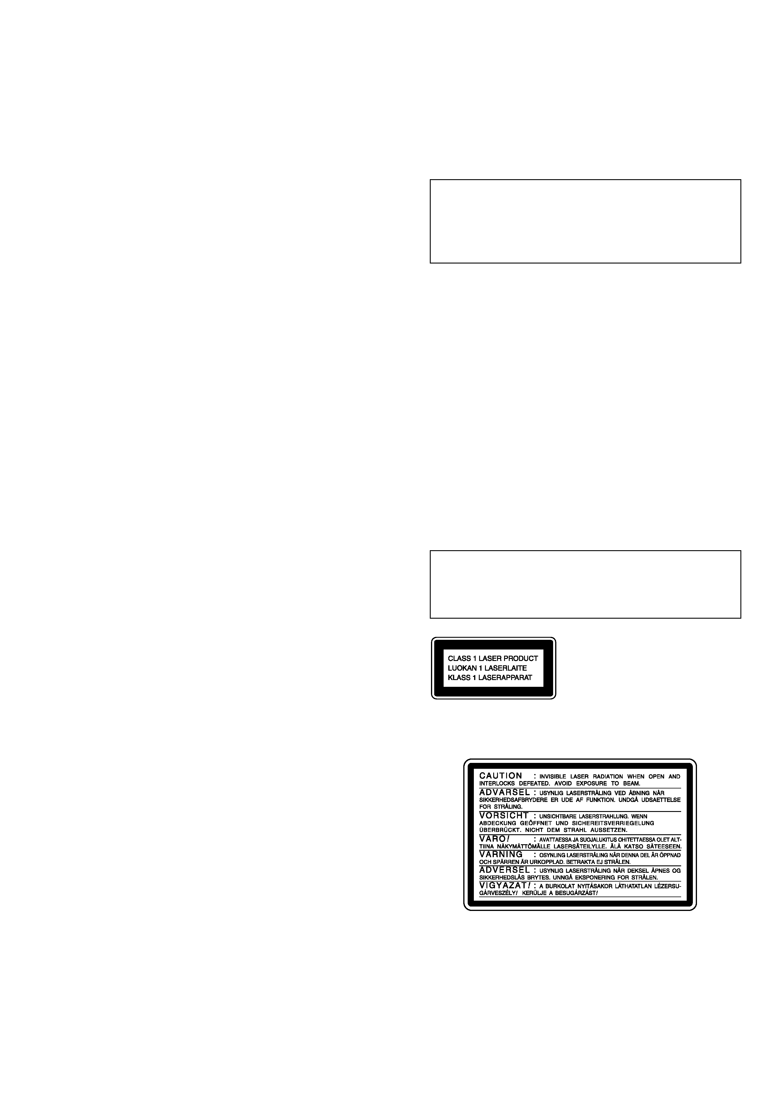
This appliance is classified
as a CLASS 1 LASER
product.
The CLASS 1 LASER
PRODUCT MARKING is
located on the rear exterior.
The following caution label is located inside the unit.
ADVARSEL
Eksplosjonsfare ved feilaktig skifte av batteri.
Benytt samme batteritype eller en tilsvarende type
anbefalt av apparatfabrikanten.
Brukte batterier kasseres i henhold til fabrikantens
instruksjoner.
VARNING
Explosionsfara vid felaktigt batteribyte.
Använd samma batterityp eller en likvärdig typ som
rekommenderas av apparattillverkaren.
Kassera använt batteri enligt gällande föreskrifter.
VAROITUS
Paristo voi räjähtää, jos se on virheellisesti asennettu.
Vaihda paristo ainoastaan laitevalmistajan suosittelemaan tyyppiin.
Hävitä käytetty paristo valmistajan ohjeiden mukaisesti.
ADVARSEL!
Lithiumbatteri-Eksplosionsfare ved fejlagtig håndtering.
Udskiftning må kun ske med batteri
af samme fabrikat og type.
Levér det brugte batteri tilbage til leverandøren.
CAUTION
Danger of explosion if battery is incorrectly replaced.
Replace only with the same or equivalent type recommended by
the manufacturer.
Discard used batteries according to the manufacturer's instructions.
CAUTION
Use of controls or adjustments or performance of procedures
other than those specified herein may result in hazardous ra-
diation exposure.