1
MICROFILM
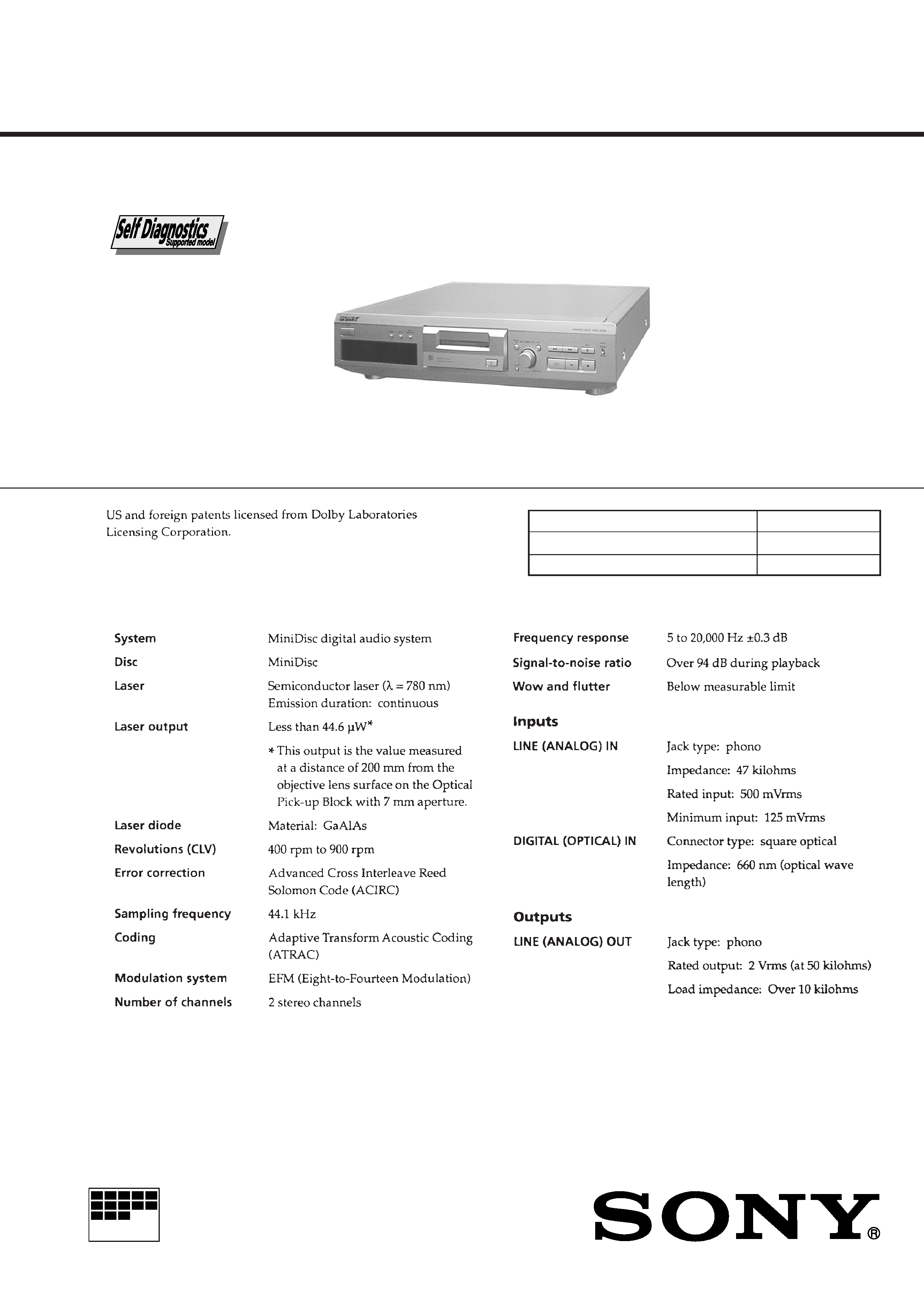
MDS-JE330
SPECIFICATIONS
SERVICE MANUAL
MINIDISC DECK
-- Continued on next page --
Model Name Using Similar Mechanism
MDS-JE520
MD Mechanism Type
MDM-5A
Optical Pick-up Type
KMS-260A/J1N
US Model
Canadian Model
AEP Model
UK Model
E Model
Australian Model
2
SELF-DIAGNOSIS FUNCTION
The self-diagnosis function consists of error codes for customers which are displayed automatically when errors occur, and error codes which
show the error history in the test mode during servicing. For details on how to view error codes for the customer, refer to the following box
in the instruction manual. For details on how to check error codes during servicing, refer to the following "Procedure for using the Self-
Diagnosis Function (Error History Display Mode)".
Procedure for using the Self-Diagnosis Function (Error History Display Mode).
Note: Perform the self-diagnosis function in the "error history display mode" in the test mode. The following describes the least required
procedure. Be careful not to enter other modes by mistake. If you set other modes accidentally, press the MENU/NO button to exit
the mode.
1. While pressing the AMS knob and
p button, connect the power plug to the outlet, and release the AMS knob and p button.
2. Rotate the AMS knob and when "[Service]" is displayed, press the YES button.
3. Rotate the AMS knob and display "ERR DP MODE".
4. Pressing the YES button sets the error history mode and displays "total rec".
5. Select the contents to be displayed or executed using the AMS knob.
6. Pressing the AMS knob will display or execute the contents selected.
7. Pressing the AMS knob another time returns to step 4.
8. Pressing the MENU/NO button displays "ERROR DP MODE" and exits the error history mode.
9. To exit the test mode, press the REPEAT button. The unit sets into the STANDBY state, the disc is ejected, and the test mode ends.
3
ITEMS OF ERROR HISTORY MODE ITEMS AND CONTENTS
Selecting the Test Mode
Display
total rec
total play
retry err
total err
err history
er refresh
tm refresh
Details of History
No error
Read error. PTOC cannot be read
(DISC ejected)
TOC error. UTOC error
(DISC not ejected)
Loading error
Address cannot be read (Servo has deviated)
Displays the recording time.
Displayed as "rh".
The displayed time is the total time the laser is set to the high power state.
This is about 1/4 of the actual recording time.
The time is displayed in decimal digits from 0h to 65535h.
Displays the play time.
Displayed as "ph". The time displayed is the total actual play time. Pauses are not counted.
The time is displayed in decimal digits from 0h to 65535h.
Displays the total number of retries during recording and number of retry errors during play.
Displayed as "r p".
"r" indicates the retries during recording while "p" indicates the retry errors during play.
The number of retries and retry errors are displayed in hexadecimal digits from 00 to FF.
Displays the total number of errors.
Displayed as "total ".
The number of errors is displayed in hexadecimal digits from 00 to FF.
Displays the 10 latest errors.
Displayed as "0 E@@".
indicates the history number. The smaller the number, the more recent is the error. (00 is the latest).
@@ indicates the error code.
Refer to the following table for the details. The error history can be switched by rotating the AMS knob.
Mode which erases the "retry err", "total err", and "err history" histories.
When returning the unit to the customer after completing repairs, perform this to erase the past error history,
After pressing the AMS button and "er refresh?" is displayed, press the YES button to erase the history.
"Complete!" will be displayed momentarily.
Be sure to check the following when this mode has been executed.
· The data has been erased.
· The mechanism operates normally when recording and play are performed.
Mode which erases the "total rec" and "total play" histories.
These histories serve as approximate indications of when to replace the optical pickup.
If the optical pickup has been replaced, perform this operation and erase the history.
After pressing the AMS button and "tm refresh?" is displayed, press the YES button to erase the history.
"Complete!" will be displayed momentarily.
Be sure to check the following when this mode has been executed.
· The data has been erased.
· The mechanism operates normally when recording and play are performed.
Table of Error Codes
Error Code
E00
E01
E02
E03
E04
E05
E06
E07
E08
E09
E0A
FOK has deviated
Cannot focus (Servo has deviated)
Recording retry
Recording retry error
Playback retry error
(Access error)
Play retry error (C2 error)
Details of Error
Error Code
Details of Error
4
CAUTION
Use of controls or adjustments or performance of procedures
other than those specified herein may result in hazardous ra-
diation exposure.
Notes on chip component replacement
· Never reuse a disconnected chip component.
· Notice that the minus side of a tantalum capacitor may be
damaged by heat.
Flexible Circuit Board Repairing
· Keep the temperature of soldering iron around 270°C
during repairing.
· Do not touch the soldering iron on the same conductor of the
circuit board (within 3 times).
· Be careful not to apply force on the conductor when soldering
or unsoldering.
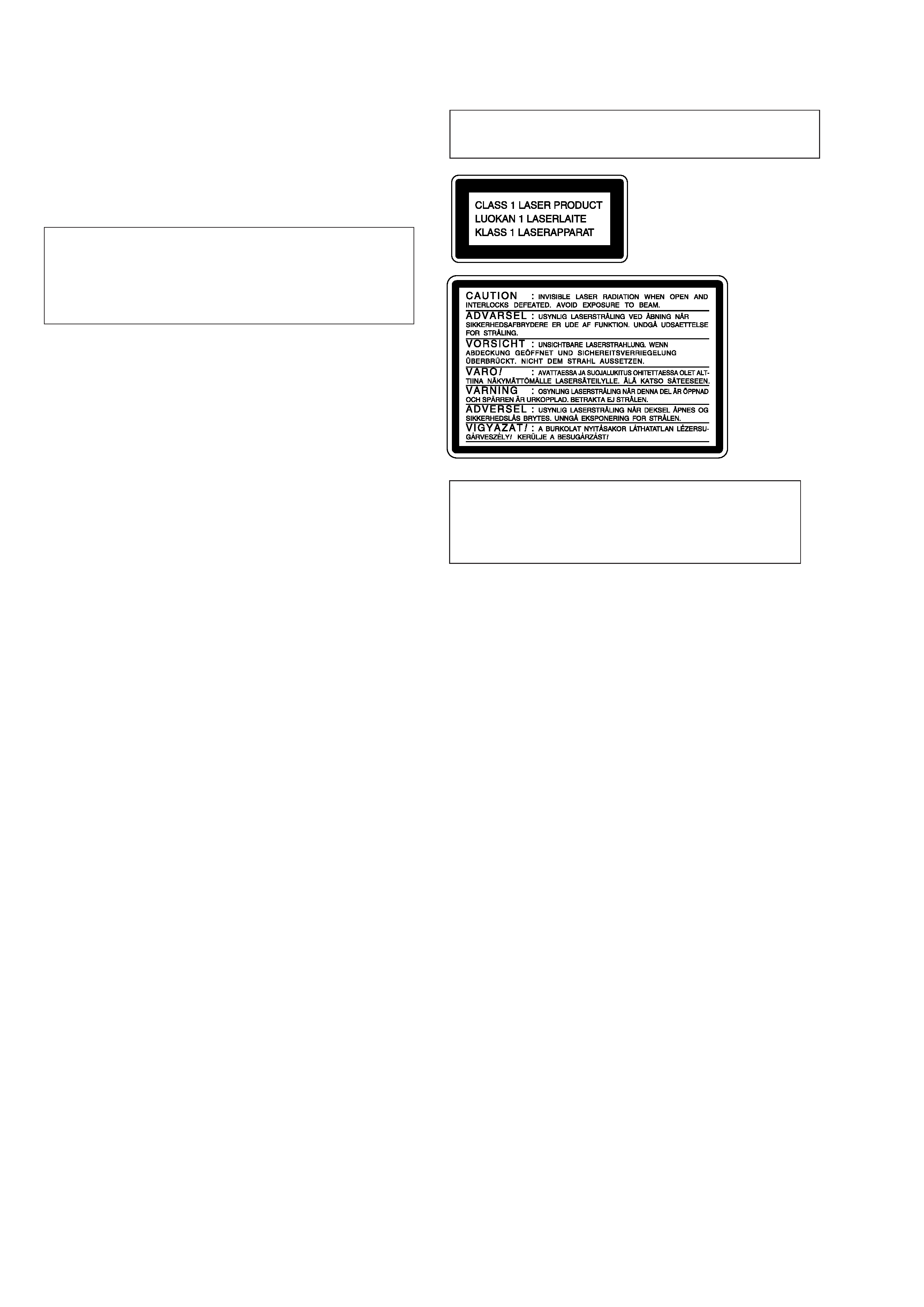
Laser component in this product is capable of emitting radiation
exceeding the limit for Class 1.
This appliance is classified as
a CLASS 1 LASER product.
The CLASS 1 LASER PROD-
UCT MARKING is located on
the rear exterior.
This caution
label is located
inside the unit.
CAUTION
Danger of explosion if battery is incorrectly replaced.
Replace only with the same or equivalent type recommended by
the equipment manufacturer.
Discard used batteries according to manufacture's instructions.
ADVARSEL!
Lithiumbatteri - Eksplosionsfare ved fejlagtig håndtering.
Udskiftning må kun ske med batteri af samme fabrikat og type.
Levér det brugte batteri tilbage til leverandøren.
ADVARSEL
Eksplosjonsfare ved feilakting skifte av batteri.
Benytt samme batteritype eller en tilsvarende type anbefalt av
apparatfabrikanten.
Brukte batterier katterier kasseres i henhold til fabrikantens
VARNIG
Explosionsfara vid felaktigt batteribyte.
Använd samma batterityp eller en likvärdig typ som rekommenderas
av apparattillverkaren.
Kassera använt batteri enligt gällande föreakrifter.
VAROITUS
Parist voi räjähtää, jos se on virheellisesti asennettu.
Vaihda paristo ainoastaan laitevalmistajan suosittelemaan tyyppiin.
Hävitä käytetty paristo valmistajan ohjeiden mukaisesti.
SAFETY-RELATED COMPONENT WARNING !!
COMPONENTS IDENTIFIED BY MARK
! OR DOTTED LINE
WITH MARK
! ON THE SCHEMATIC DIAGRAMS AND IN
THE PARTS LIST ARE CRITICAL TO SAFE OPERATION.
REPLACE THESE COMPONENTS WITH SONY PARTS
WHOSE PART NUMBERS APPEAR AS SHOWN IN THIS
MANUAL OR IN SUPPLEMENTS PUBLISHED BY SONY.
ATTENTION AU COMPOSANT AYANT RAPPORT
À LA SÉCURITÉ!!
LES COMPOSANTS IDENTIFIÉS PAR UNE MARQUE
!SUR
LES DIAGRAMMES SCHÉMATIQUES ET LA LISTE DES
PIÈCES SONT CRITIQUES POUR LA SÉCURITÉ DE
FONCTIONNEMENT. NE REMPLACER CES COMPOSANTS
QUE PAR DES PIÈCES SONY DONT LES NUMÉROS
SONT DONNÉS DANS CE MANUEL OU DANS LES
SUPPLÉMENTS PUBLIÉS PAR SONY.
5
4-216-349-0
US model
4-216-349-1
Canadian model
4-216-349-2
AEP, UK model
4-216-349-3
Australian model
4-216-349-4
Singapore model
4-216-349-5
Hong Kong model
MODEL IDENTIFICATION
-- BACK PANEL --
SAFETY CHECK-OUT
After correcting the original service problem, perform the follow-
ing safety checks before releasing the set to the customer:
Check the antenna terminals, metal trim, "metallized" knobs, screws,
and all other exposed metal parts for AC leakage. Check leakage as
described below.
LEAKAGE
The AC leakage from any exposed metal part to earth Ground and
from all exposed metal parts to any exposed metal part having a
return to chassis, must not exceed 0.5 mA (500 microampers). Leak-
age current can be measured by any one of three methods.
1. A commercial leakage tester, such as the Simpson 229 or RCA
WT-540A. Follow the manufacturers' instructions to use these
instruments.
2. A battery-operated AC milliammeter. The Data Precision 245
digital multimeter is suitable for this job.
3. Measuring the voltage drop across a resistor by means of a VOM
or battery-operated AC voltmeter. The "limit" indication is 0.75
V, so analog meters must have an accurate low-voltage scale.
The Simpson 250 and Sanwa SH-63Trd are examples of a pas-
sive VOM that is suitable. Nearly all battery operated digital
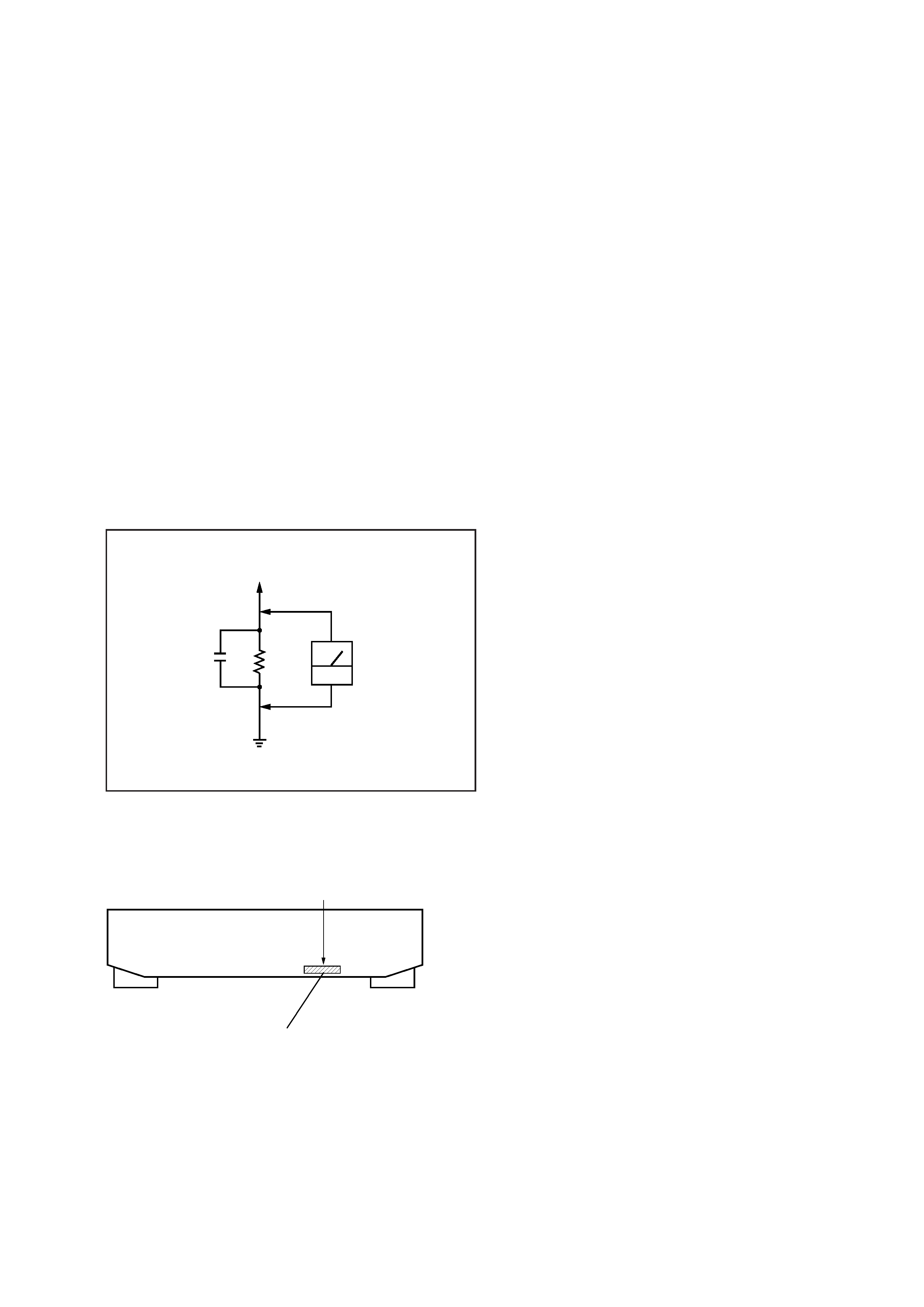
multimeters that have a 2V AC range are suitable. (See Fig. A)
Fig. A. Using an AC voltmeter to check AC leakage.
TABLE OF CONTENTS
1. SERVICING NOTE .......................................................... 6
2. GENERAL ........................................................................ 11
3. DISASSEMBLY
3-1. Case and Front Panel .......................................................... 12
3-2. Slider (Cam) ........................................................................ 12
3-3. Base Unit (MBU-5A) and BD Board .................................. 13
3-4. SW Board and Loading Motor (M103) .............................. 13
4. TEST MODE ..................................................................... 14
5. ELECTRICAL ADJUSTMENTS ............................... 19
6. DIAGRAMS
6-1. Circuit Boards Location ...................................................... 28
6-2. Block Diagrams
· BD Section ....................................................................... 29
· Main Section .................................................................... 31
6-3. Printed Wiring Board BD Section ................................. 35
6-4. Schematic Diagram BD Section (1/2) ........................... 37
Schematic Diagram BD Section (2/2) ........................... 39
6-5. Schematic Diagram Main Section (1/2) ........................ 41
Schematic Diagram Main Section (2/2) ........................ 43
6-6. Printed Wiring Board Main Section .............................. 45
6-7. Printed Wiring Board Panel Section ............................. 47
6-8. Schematic Diagram Panel Section ................................ 49
6-9. Schematic Diagram BD Switch Section ....................... 51
6-10. Printed Wiring Board BD Switch Section .................. 51
6-11. IC Block Diagrams ........................................................... 52
6-12. IC Pin Functions ............................................................... 55
7. EXPLODED VIEWS
7-1. Case and Back Panel Section .............................................. 61
7-2. Front Panel Section ............................................................. 62
7-3. Mechanism Section (MDM-5A) ......................................... 63
7-4. Base Unit Section (MBU-5A) ............................................. 64
8. ELECTRICAL PARTS LIST ........................................ 65
0.15
µF
To Exposed Metal
Parts on Set
1.5k
AC
voltmeter
(0.75V)
Earth Ground
Parts No.