MDS-JB940
US Model
Canadian Model
AEP Model
UK Model
SERVICE MANUAL
MINIDISC DECK
Model Name Using Similar Mechanism
NEW
MD Mechanism Type
MDM-7A
Optical Pick-up Name
KMS-260B/J1N
U.S and foreign patents licensed from Dolby
Laboratories Licensing Corporation.
SPECIFICATIONS
Inputs
Outputs
System
MiniDisc digital audio system
Disc
MiniDisc
Laser
Semiconductor laser (
= 780 nm)
Emission duration: continuous
Laser output
MAX 44.6
µW1)
1) This output is the value
measured at a distance of
200 mm from the objective lens
surface on the Optical Pick-up
Block with 7 mm aperture.
Laser diode
Material: GaAlAs
Revolutions (CLV)
400 rpm to 900 rpm
Error correction
ACIRC (Advanced Cross Interleave
Reed Solomon Code)
Sampling frequency
44.1 kHz
Coding
ATRAC (Adaptive TRansform
Acoustic Coding)/ATRAC 3
Modulation system
EFM (Eight-to-Fourteen
Modulation)
Number of channels
2 stereo channels
Frequency response
5 to 20,000 Hz
±0.3 dB
Signal-to-noise ratio
Over 100 dB during play
Wow and flutter
Below measurable limit
ANALOG IN
Jack type: phono
Impedance: 47 kilohms
Rated input: 500 mVrms
Minimum input: 125 mVrms
DIGITAL OPTICAL IN1 Connector type: square optical
Impedance: 660 nm (optical wave
length)
DIGITAL OPTICAL IN2 Connector type: square optical
Impedance: 660 nm (optical wave
length)
DIGITAL COAXIAL IN
Jack type: phono
Impedance: 75 ohms
Rated input: 0.5 Vp-p,
±20 %
PHONES
Jack type: stereo phone
Rated output: 28 mW
Load impedance: 32 ohms
ANALOG OUT
Jack type: phono
Rated output: 2 Vrms (at 50
kilohms)
Load impedance: over 10 kilohms
DIGITAL OPTICAL OUT Connector type: square optical
Rated output: 18 dBm
Load impedance: 660 nm (optical
wave length)
DIGITAL COAXIAL OUT Jack type: phono
Rated output: 0.5 Vp-p (at 75 ohms)
Load impedance: 75 ohms
General
Power requirements
Supplied accessories
US and foreign patents licensed from Dolby Laboratories.
Design and specifications are subject to change without
notice.
Where purchased
Power requirements
U.S.A. and Canada
120 V AC, 60 Hz
Europe
230 V AC, 50/60 Hz
Power consumption
18 W
Dimensions (approx.)
430
× 111 × 286 mm (17 × 4 3/8 ×
11 3/8 in.) (w/h/d) incl. projecting
parts and controls
Mass (approx.)
5.3 kg (11 lbs 11 oz)
This MD deck comes with the following items:
Audio connecting cords (2)
Optical cable (1)
Remote commander (remote) (1)
R6 (size-AA) batteries (2)
Ver. 1.2 2005.12
Sony Corporation
Home Audio Division
Published by Sony Engineering Corporation
9-929-274-13
2005L16-1
© 2005.12
2
After correcting the original service problem, perform the
following safety checks before releasing the set to the customer:
Check the antenna terminals, metal trim, "metallized" knobs, screws,
and all other exposed metal parts for AC leakage. Check leakage as
described below.
LEAKAGE
The AC leakage from any exposed metal part to earth ground and
from all exposed metal parts to any exposed metal part having a
return to chassis, must not exceed 0.5 mA (500 microamperes).
Leakage current can be measured by any one of three methods.
1.
A commercial leakage tester, such as the Simpson 229 or RCA
WT-540A. Follow the manufacturers' instructions to use these
instruments.
2.
A battery-operated AC milliammeter. The Data Precision 245
digital multimeter is suitable for this job.
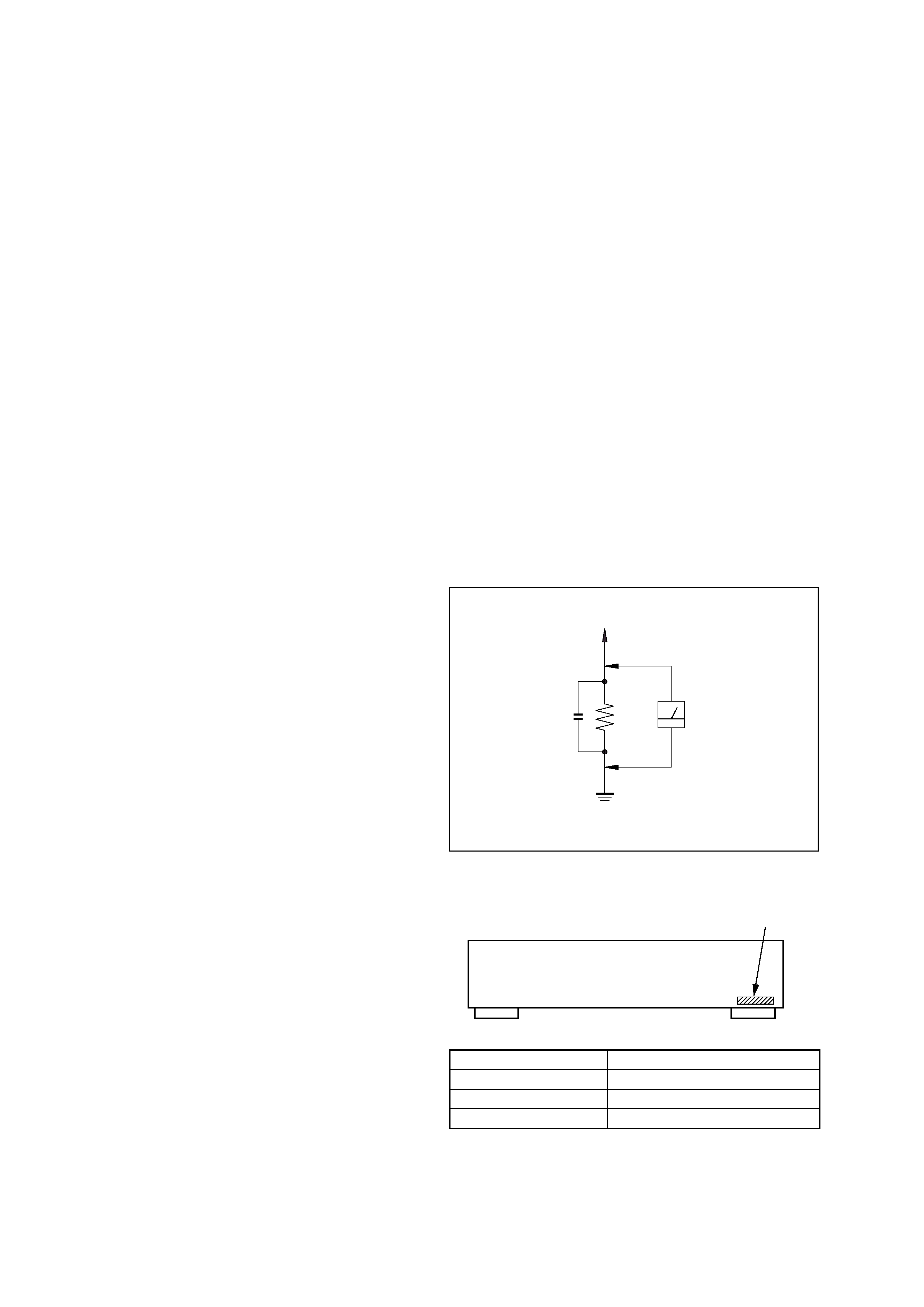
3.
Measuring the voltage drop across a resistor by means of a
VOM or battery-operated AC voltmeter. The "limit" indication
is 0.75 V, so analog meters must have an accurate low-voltage
scale. The Simpson 250 and Sanwa SH-63Trd are examples of
a passive VOM that is suitable. Nearly all battery operated
digital multimeters that have a 2V AC range are suitable. (See
Fig. A)
SAFETY CHECK-OUT
To Exposed Metal
Parts on Set
0.15
µF
1.5 k
AC
Voltmeter
(0.75 V)
Earth Ground
Fig. A. Using an AC voltmeter to check AC leakage.
TABLE OF CONTENTS
MODEL IDENTIFICATION
-- BACK PANEL --
Model
AEP, UK models
Canadian model
US model
Part No.
4-228-507-0s
4-228-507-1s
4-228-507-2s
Part No.
SELF-DIAGNOSIS FUNCTION ········································ 4
1. SERVICE NOTE ······························································· 6
2. GENERAL ········································································ 11
3. DISASSEMBLY ······························································ 14
4. TEST MODE ··································································· 17
5. ELECTRICAL ADJUSTMENTS ······························ 22
6. DIAGRAMS
6-1. Block Diagram
MAIN Section ································ 31
6-2. Block Diagram
DISPLAY/POWER Section ··········· 32
6-3. Note for Printed Wiring Boards and
Schematic Diagrams ···················································· 33
6-4. Circuit Board Location ················································ 33
6-5. Waveforms ··································································· 34
6-6. Printed Wiring Board
BD Board ····························· 35
6-7. Schematic Diagram
BD Board (1/2) ······················· 36
6-8. Schematic Diagram
BD Board (2/2) ······················· 37
6-9. Printed Wiring Board
HP Board/KEY Board ·········· 38
6-10. Schematic Diagram
HP Board/KEY Board ············ 38
6-11. Schematic Diagram
MAIN Board (1/3) ·················· 39
6-12. Schematic Diagram
MAIN Board (2/3) ·················· 40
6-13. Schematic Diagram
MAIN Board (3/3) ·················· 41
6-14. Printed Wiring Board
MAIN Board (Side A) ·········· 42
6-15. Printed Wiring Board
MAIN Board (Side B) ·········· 43
6-16. Printed Wiring Board
PANEL Section ···················· 44
6-17. Schematic Diagram
PANEL Section ······················· 45
6-18. Schematic Diagram
AC Board ································ 46
6-19. Printed Wiring Board
AC Board ······························ 47
6-20. IC Block Diagrams ······················································ 48
6-21. IC Pin Function Description ········································ 53
7. EXPLODED VIEWS ······················································ 60
8. ELECTRICAL PARTS LIST ······································· 64
3
SAFETY-RELATED COMPONENT WARNING!!
COMPONENTS IDENTIFIED BY MARK 0 OR DOTTED LINE WITH
MARK 0 ON THE SCHEMATIC DIAGRAMS AND IN THE PARTS
LIST ARE CRITICAL TO SAFE OPERATION. REPLACE THESE
COMPONENTS WITH SONY PARTS WHOSE PART NUMBERS
APPEAR AS SHOWN IN THIS MANUAL OR IN SUPPLEMENTS
PUBLISHED BY SONY.
ATTENTION AU COMPOSANT AYANT RAPPORT
À LA SÉCURITÉ!
LES COMPOSANTS IDENTIFÉS PAR UNE MARQUE 0 SUR LES
DIAGRAMMES SCHÉMATIQUES ET LA LISTE DES PIÈCES SONT
CRITIQUES POUR LA SÉCURITÉ DE FONCTIONNEMENT. NE
REMPLACER CES COMPOSANTS QUE PAR DES PIÈSES SONY
DONT LES NUMÉROS SONT DONNÉS DANS CE MANUEL OU
DANS LES SUPPÉMENTS PUBLIÉS PAR SONY.
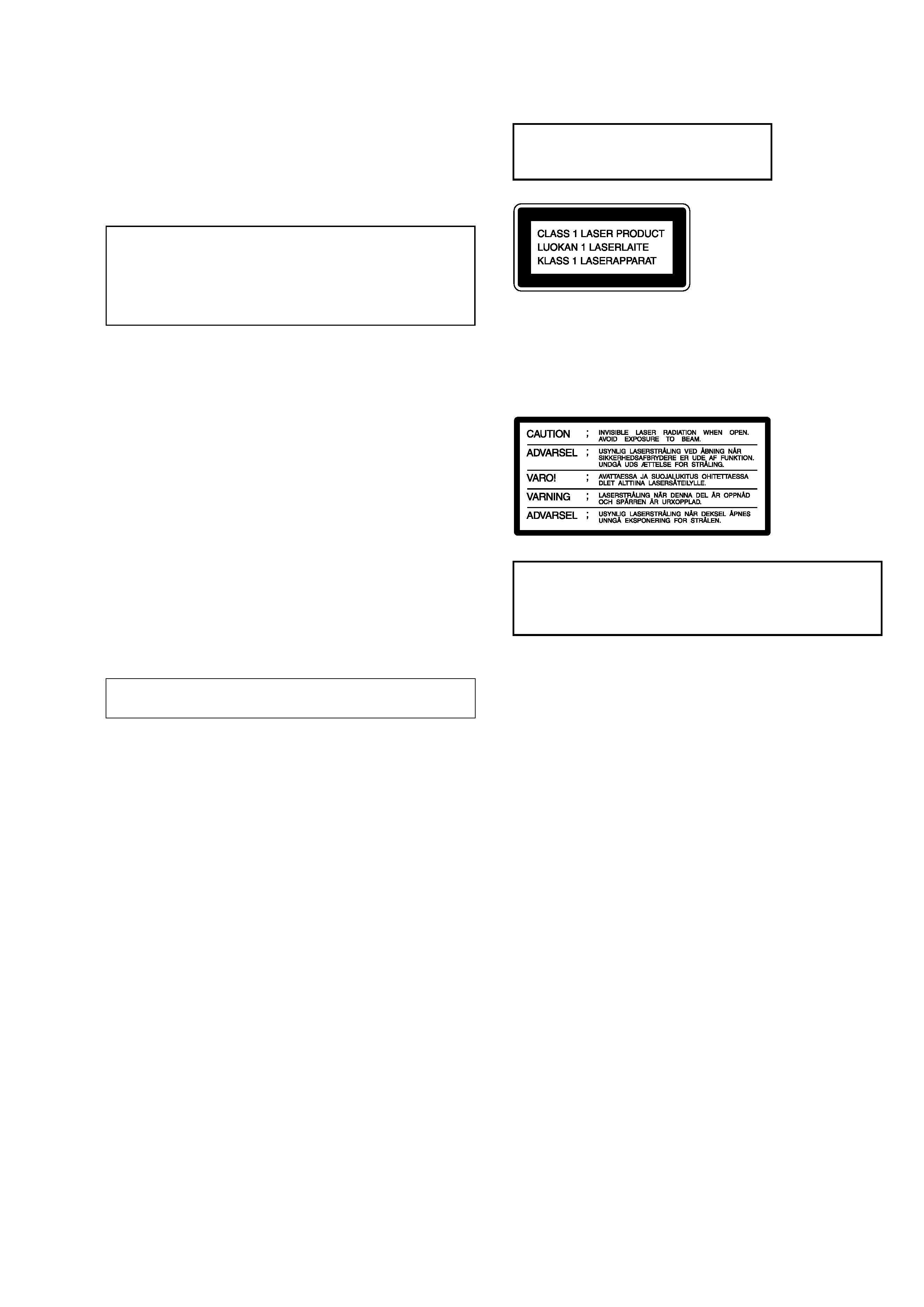
This appliance is classified as a CLASS 1 LASER product. The
CLASS 1 LASER PRODUCT MARKING is located on the rear
exterior.
The following caution label is located inside the unit.
Laser component in this product is capable
of emitting radiation exceeding the limit for
Class 1.
CAUTION
Use of controls or adjustments or performance of procedures
other than those specified herein may result in hazardous radiation
exposure.
Notes on chip component replacement
· Never reuse a disconnected chip component.
· Notice that the minus side of a tantalum capacitor may be
damaged by heat.
Flexible Circuit Board Repairing
· Keep the temperature of soldering iron around 270°C
during repairing.
· Do not touch the soldering iron on the same conductor of the
circuit board (within 3 times).
· Be careful not to apply force on the conductor when soldering
or unsoldering.
ADVARSEL
Eksplosjonsfare ved feilaktig skifte av batteri.
Benytt samme batteritype eller en tilsvarende type
anbefalt av apparatfabrikanten.
Brukte batterier kasseres i henhold til fabrikantens
instruksjoner.
VARNING
Explosionsfara vid felaktigt batteribyte.
Använd samma batterityp eller en likvärdig typ som
rekommenderas av apparattillverkaren.
Kassera använt batteri enligt gällande föreskrifter.
VAROITUS
Paristo voi räjähtää, jos se on virheellisesti asennettu.
Vaihda paristo ainoastaan laitevalmistajan suosittelemaan tyyppiin.
Hävitä käytetty paristo valmistajan ohjeiden mukaisesti.
ADVARSEL!
Lithiumbatteri-Eksplosionsfare ved fejlagtig håndtering.
Udskiftning må kun ske med batteri
af samme fabrikat og type.
Levér det brugte batteri tilbage til leverandøren.
CAUTION
Danger of explosion if battery is incorrectly replaced.
Replace only with the same or equivalent type recommended by
the manufacturer.
Discard used batteries according to the manufacturer's instructions.
The laser diode in the optical pick-up block may suffer electrostatic
break-down because of the potential difference generated by the
charged electrostatic load, etc. on clothing and the human body.
During repair, pay attention to electrostatic break-down and also
use the procedure in the printed matter which is included in the
repair parts.
The flexible board is easily damaged and should be handled with
care.
NOTES ON LASER DIODE EMISSION CHECK
The laser beam on this model is concentrated so as to be focused on
the disc reflective surface by the objective lens in the optical pick-
up block. Therefore, when checking the laser diode emission,
observe from more than 30 cm away from the objective lens.
NOTES ON HANDLING THE OPTICAL PICK-UP
BLOCK OR BASE UNIT
4
SELF-DIAGNOSIS FUNCTION
The self-diagnosis function consists of error codes for customers which are displayed automatically when errors occur, and error codes which
show the error history in the test mode during servicing. For details on how to view error codes for the customer, refer to the following box
in the instruction manual. For details on how to check error codes during servicing, refer to the following "Procedure for using the Self-
Diagnosis Function (Error History Display Mode)".
The deck's self-diagnosis function automatically checks the condition of the MD deck when an error occurs, then issues a three- or five-digit
code and an error message on the display. If the code and message alternate, find them in the following table and perform the indicated
countermeasure. Should the problem persist, consult your nearest Sony dealer.
PROCEDURE FOR USING THE SELF-DIAGNOSIS FUNCTION (ERROR HISTORY DISPLAY MODE)
Note:
Perform the self-diagnosis function in the "error history display mode" in the test mode. The following describes the least required procedure. Be
careful not to enter other modes by mistake. If you set other modes accidentally, press the MENU/NO button to exit the mode.
1. While pressing the l AMS L knob and x button, connect the power plug to the outlet, and release the l AMS L knob and
x button. When the test mode is set "[Check]" is displayed.
2. Turn the l AMS L knob and when "[Service]" is displayed, press the YES button.
3. Turn the l AMS L knob to display "Err Display".
4. Press the YES button to sets the error history mode and displays "op rec tm".
5. Select the contents to be displayed or executed using the l AMS L knob.
6. Press the l AMS L knob to display or execute the contents selected.
7. Press the l AMS L knob another time to return to step 4.
8. Press the MENU/NO button to display "Err Display" and release the error history mode.
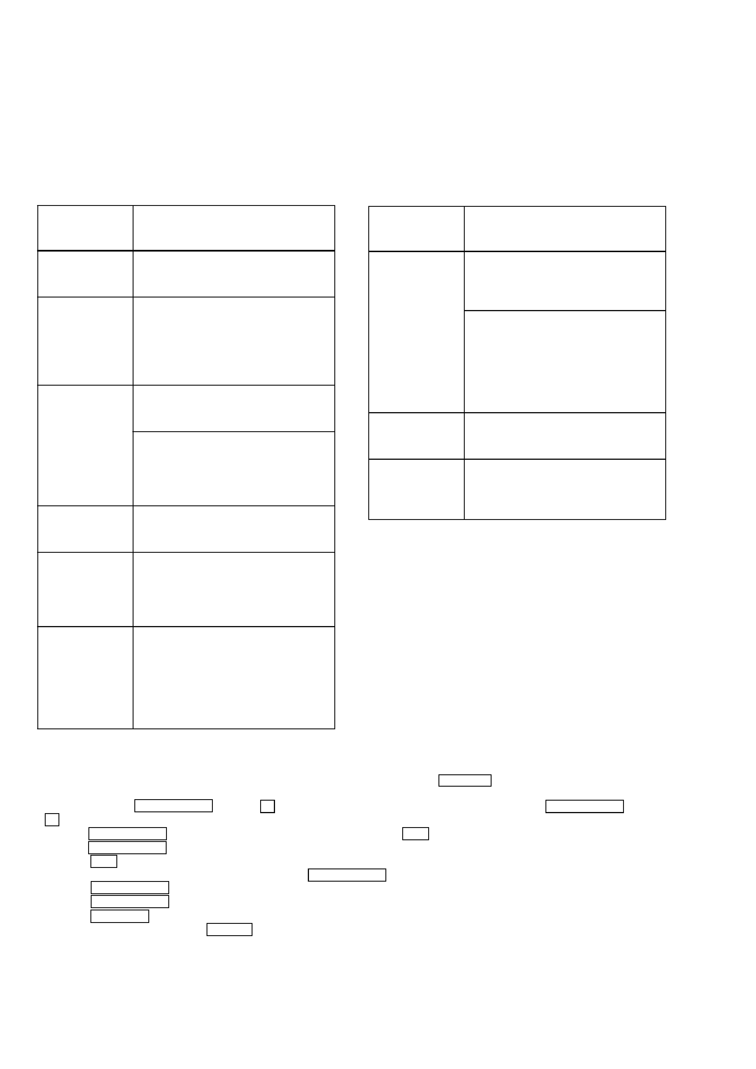
9. To release the test mode, press the REPEAT button. The unit sets into the STANDBY state and the test mode ends.
Three- or five-
digit code/
Message
Cause/Remedy
C11/Protected
The inserted MD is record-protected.
Take out the MD and close the record-
protect slot (page 15).
C12/Cannot Copy
You tried to record a CD with a format
that the external device connected to the
deck does not support, such as CD-ROM
or video CD.
Remove the disc and insert a music
CD.
C13/REC Error
The recording was not made properly.
Set the deck in a stable surface, and
repeat the recording procedure.
The inserted MD is dirty (with smudges,
fingerprints, etc.), scratched, or
substandard in quality.
Replace the disc and repeat the
recording procedure.
C13/Read Error
The deck could not read the TOC on the
MD properly.
Take out the MD and insert it again.
C14/Toc Error
The deck could not read the TOC on the
MD properly.
Insert another disc.
If possible, erase all the tracks on the
MD (page 32).
C41/Cannot Copy
The sound source is a copy of
commercially available music software, or
you tried to record a CD-R (Recordable
CD).
The Serial Copy Management System
prevents making a digital copy
(page 52). You cannot record a CD-R.
C71/Din Unlock
The sporadic appearance of this message
is caused by the digital signal being
recorded. This will not affect the
recording.
While recording from a digital component
connected through the DIGITAL IN
connector, the digital connecting cable
was unplugged or the digital component
turned off.
Connect the cable or turn the digital
component back on.
E0001/
MEMORY NG
There is an error in the internal data that
the deck needs in order to operate.
Consult your nearest Sony dealer.
E0101/
LASER NG
There is a problem with the optical
pickup.
The optical pickup may have failed.
Consult your nearest Sony dealer.
Three- or five-
digit code/
Message
Cause/Remedy
5
[ITEMS OF ERROR HISTORY MODE ITEMS AND CONTENTS]
Details of History
Displays the total recording time.
When the total recording time is one minute or longer, displays the time and minute.
When the total recording time is less than one minute, displays "Under 1 min".
The displayed time is about 1/4 of the actual recording time when the laser is set to the high power state.
Displays the total playback time.
When the total playback time is one minute or longer, displays the time and minute.
When the total playback time is less than one minute, displays "Under 1 min".
Displays the total time when the spindle motor rotates.
When the total rotation time is one minute or longer, displays the time and minute.
When the total rotation time is less than one minute, displays "Under 1 min".
Displays the total number of retries during recording and number of retry errors during playback.
Displayed as "r xx p yy". "xx" indicates the number of retries during recording, "yy" indicates the number of retry
errors during playback.
The numbers are displayed in hexadecimal from 00 to FF.
Displays the total number of errors.
Displayed as "total xx". The number is displayed in hexadecimal from 00 to FF.
Displays the last ten errors.
Displayed as "0x ErrCd@@".
"x" indicates the history number. A smaller number indicates a more recent error (00 is the latest). @@ indicates the
error code. The error history number is selected by turning the l AMS L knob.
Displays the last five retry addresses.
Displayed as "xx ADRS yyyy". "xx" indicates the history number. "yyyy" indicates the cluster where the retry
occurred. The history number is selected by turning the l AMS L knob.
Mode which erases the error history and the retry address history
[Operation procedure]
1
When "er refresh" is displayed, press the l AMS L knob.
2
After the display changes to "er refresh?", press the YES button.
The "Complete!" message indicates that the operation has ended.
After executing this mode, be sure to check the following:
· The data has been erased.
· The mechanism runs normally when recording and playback are performed.
Mode which erases the total time of "op rec tm" and "op play tm"
These histories are used as a guideline for the time to replace the optical pick-up. After replacing the optical pick-up,
perform this operation to erase the history.
[Operation procedure]
1
When "op change" is displayed, press the l AMS L knob.
2
After the display changes to "op change?", press the YES button.
The "Complete!" message indicates that the operation has ended.
Mode which erases the total time of "spdl rp tm"
The history is used as a guideline for the time to replace the spindle motor. After replacing the spindle motor, perform
this operation to erase the history.
[Operation procedure]
1
When "spdl change" is displayed, press the l AMS L knob.
2
After the display changes to "spdl change?", press the YES button.
The "Complete!" message indicates that the operation has ended.
Table of Error Codes
Display
op rec tm
op play tm
spdl rp tm
retry err
total err
err history
retry adrs
er refresh
op change
spdl change
Error Code
10
12
20
21
22
23
24
30
Details of Error
Loading error
The combination of loading switches is not acceptable.
Time out. The beginning of PTOC cannot be read.
Contents error. The beginning of PTOC can be read.
Time out. Access to UTOC failed.
Time out. UTOC cannot be read.
Contents error of UTOC
Playback start error
Error Code
31
40
41
42
43
50
51
Details of Error
There is an abnormality in the sector contents.
An error caused a retry during continuous recording.
Retry was executed due to DRAM overflow.
Retry was executed during TOC writing.
S.F Edit was aborted due to retry.
Address cannot be read although access processing is
not in progress.
Runaway due to focus NG