SERVICE MANUAL
Type: Closed, dynamic
Driver units: 50 mm, dome type
Power handling capacity: 3,000 mW (IEC*)
Impedance: 24
at 1 kHz
Sensitivity: 106 dB/mW
Frequency response: 5 30,000 Hz
Cord: 2.5 m (8.2 ft), OFC litz cord
Plug: Gold-plated stereo mini plug
Mass: Approx. 260 g (9.18 oz) without cord
Supplied accessories: Gold-plated Unimatch plug adapter (1)
Extension cord (2.5 m, stereo mini jack y stereo mini plug) (1)
* IEC = International Electrotechnical Commission
Design and specifications are subject to change without notice.
STEREO HEADPHONES
US Model
AEP Model
E Model
SPECIFICATIONS
MDR-XD400
Ver. 1.1 2005.02
9-879-480-02
2005B05-1
© 2005.02
Sony Corporation
Personal Audio Company
Published by Sony Engineering Corporation
MDR-XD400
2
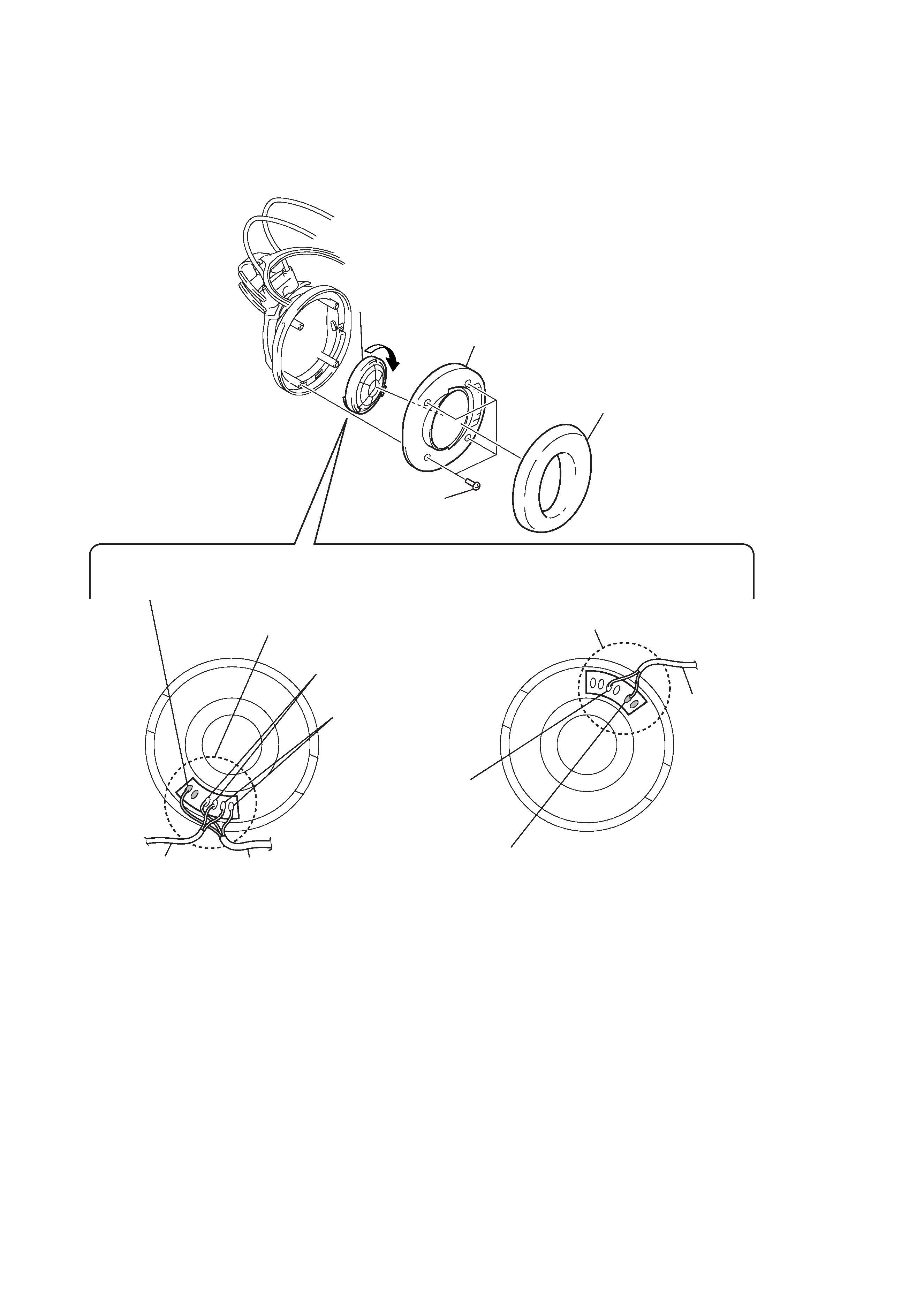
Note: Follow the disassembly procedure in the numerical order given.
DRIVER (Lch/Rch)
(For both left and right headphones, disassemble through the same procedure)
SECTION 1
DISASSEMBLY
1
ear pad
2
four screws
(B2.6)
3
Remove five solders of the head
band cord and cord (with plug).
4
Rotate the driver (Lch/Rch) in
the arrow direction to remove.
5
front plate assy
cord (with plug)
head band cord
3
Remove two solders
of the head band cord.
DRIVER (Lch)
head band cord
Connect a lead wire of the cord (with plug) (green) to the terminal
with a marking.
(The location of a marking may differ from the illustration.)
Connect a lead wire of the head band cord (red) to the terminal
with a marking.
(The location of a marking may differ from the illustration.)
DRIVER (Rch)
Natural color lead wire
connecting locations
Natural color lead wire
connecting locations
Red color lead wire
connecting locations
3
MDR-XD400
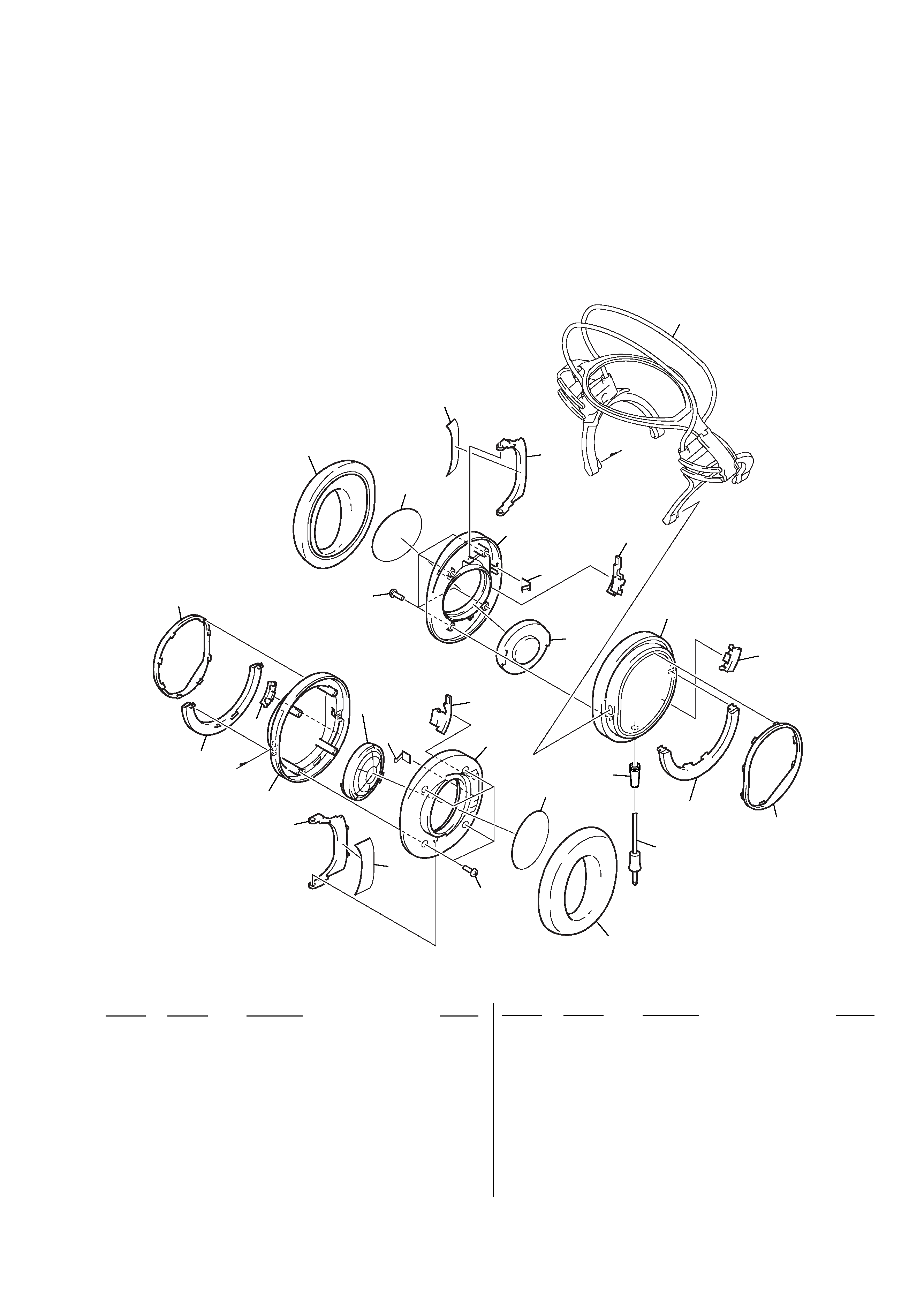
SECTION 2
EXPLODED VIEWS
Ref. No.
Part No.
Description
Remark
Ref. No.
Part No.
Description
Remark
12-320-280-01 PAD, EAR
33-254-151-01 SCREW (B2.6), (+) P TAPPING
42-342-965-01 SEAL, FLAP
52-320-283-01 FLAP
6
X-2055-796-1 PLATE (R) ASSY, FRONT
72-342-964-01 LINK (R), FLAP
82-515-566-01 SCREEN
92-342-962-01 SPRING, FLAP
10
1-542-605-11 DRIVER (050F032) (Lch/Rch)
11
2-320-275-01 HOUSING (R)
12
2-342-961-01 CAP (R), HOUSING
13
2-320-281-01 KNOB
14
2-320-277-01 RING (R), ORNAMENTAL
15
X-2055-795-1 PLATE (L) ASSY, FRONT
16
2-342-963-01 LINK (L), FLAP
17
2-320-274-01 HOUSING (L)
18
2-320-267-01 BUSHING
19
1-829-886-11 CORD (WITH PLUG)
20
2-342-960-01 CAP (L), HOUSING
21
2-320-276-01 RING (L), ORNAMENTAL
2-1.
HOUSING SECTION
· Items marked "*" are not stocked since they
are seldom required for routine service. Some
delay should be anticipated when ordering
these items.
· The mechanical parts with no reference
number in the exploded views are not supplied.
· Accessories are given in the last of the parts
list.
NOTE:
· -XX and -X mean standardized parts, so they
may have some difference from the original
one.
· Color Indication of Appearance Parts
Example:
KNOB, BALANCE (WHITE) . . . (RED)
Parts Color
Cabinet's Color
1
head band section
1
12
13
13
3
3
14
4
4
15
5
5
16
6
17
7
18
8
8
19
9
9
20
10
10
21
11
4
MDR-XD400
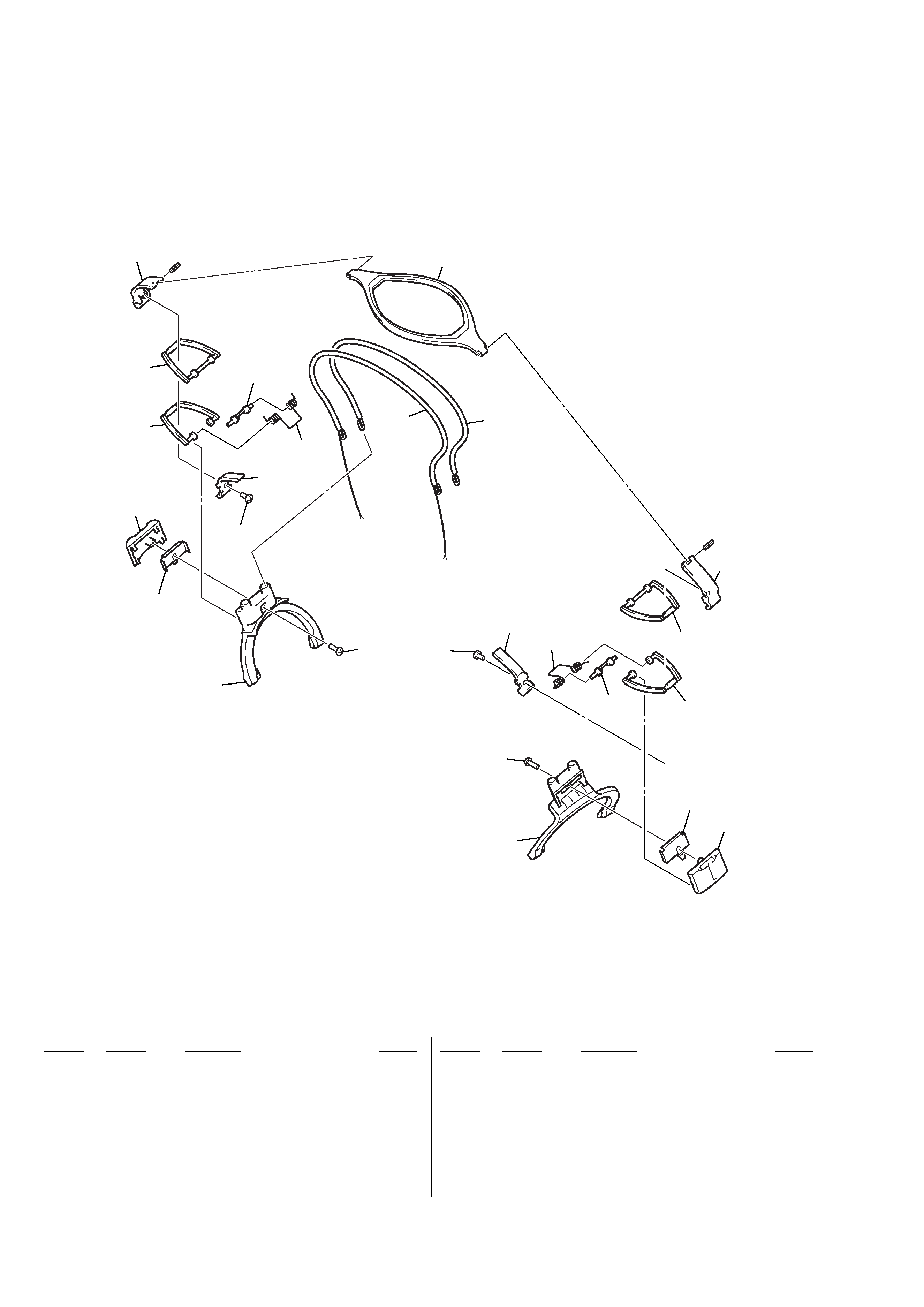
2-2.
HEAD BAND SECTION
Ref. No.
Part No.
Description
Remark
Ref. No.
Part No.
Description
Remark
51
2-320-273-01 HANGER (R)
52
2-342-957-01 RETAINER, BAND
54
3-254-029-11 SCREW
55
2-595-280-01 LID (A), HOLDER
56
2-342-956-03 SPRING, LINK
57
2-342-955-01 SHAFT, LINK
58
2-320-271-03 LINK (LOWER)
59
2-320-270-01 LINK (UPPER)
60
2-595-279-01 HOLDER (A)
61
2-320-269-03 SUSPENDER
62
2-342-958-03 LID, HANGER
63
2-320-272-01 HANGER (L)
64
3-254-151-01 SCREW (B2.6), (+) P TAPPING
65
X-2050-366-1 BAND ASSY, HEAD
66
X-2050-850-1 BAND (REAR) ASSY, HEAD
#1
7-626-305-51 PIN, SPRING 1X12
51
#1
#1
52
52
62
54
54
55
55
65
66
56
56
57
57
58
58
59
59
60
60
61
62
63
64
64

5
MDR-XD400
ACCESSORIES
Ref. No.
Part No.
Description
Remark
1-566-410-21 ADAPTOR, PLUG
(Gold-plated Unimatch plug adapter)
1-829-889-11 CORD, EXTENSION
(2.5m, stereo mini jack/stereo mini plug)