MDR-RF975R
SERVICE MANUAL
HEADPHONES
SPECIFICATIONS
US Model
MDR-RF975R is the component model block one in the MDR-RF975RK.
9-873-141-12
2001F0200-1
© 2001.6
Sony Corporation
Personal Audio Company
Shinagawa Tec Service Manual Production Group
Ver 1.1 2001. 06
Headphones
MDR-RF975R
Transmitter
TMR-RF975R
COMPONENT MODEL NAME FOR MDR-RF975RK
Headphones
Power source
DC 2.4 V: Built-in rechargeable
battery
Mass
Approx. 350 g (12.3 oz.) incl.
built-in rechargeable battery
Built-in Ni-MH rechargeable battery
Model name
NH-AAC
Voltage
1.2 V
Capacity
1,000 mAh
Design and specifications are subject to change without
notice.
2
MDR-RF975R
This section is extracted from
instruction manual.
Flexible Circuit Board Repairing
· Keep the temperature of soldering iron around 270
°C
during repairing.
· Do not touch the soldering iron on the same conductor of the
circuit board (within 3 times).
· Be careful not to apply force on the conductor when soldering
or unsoldering.
Notes on chip component replacement
· Never reuse a disconnected chip component.
· Notice that the minus side of a tantalum capacitor may be
damaged by heat.
SECTION 1
GENERAL
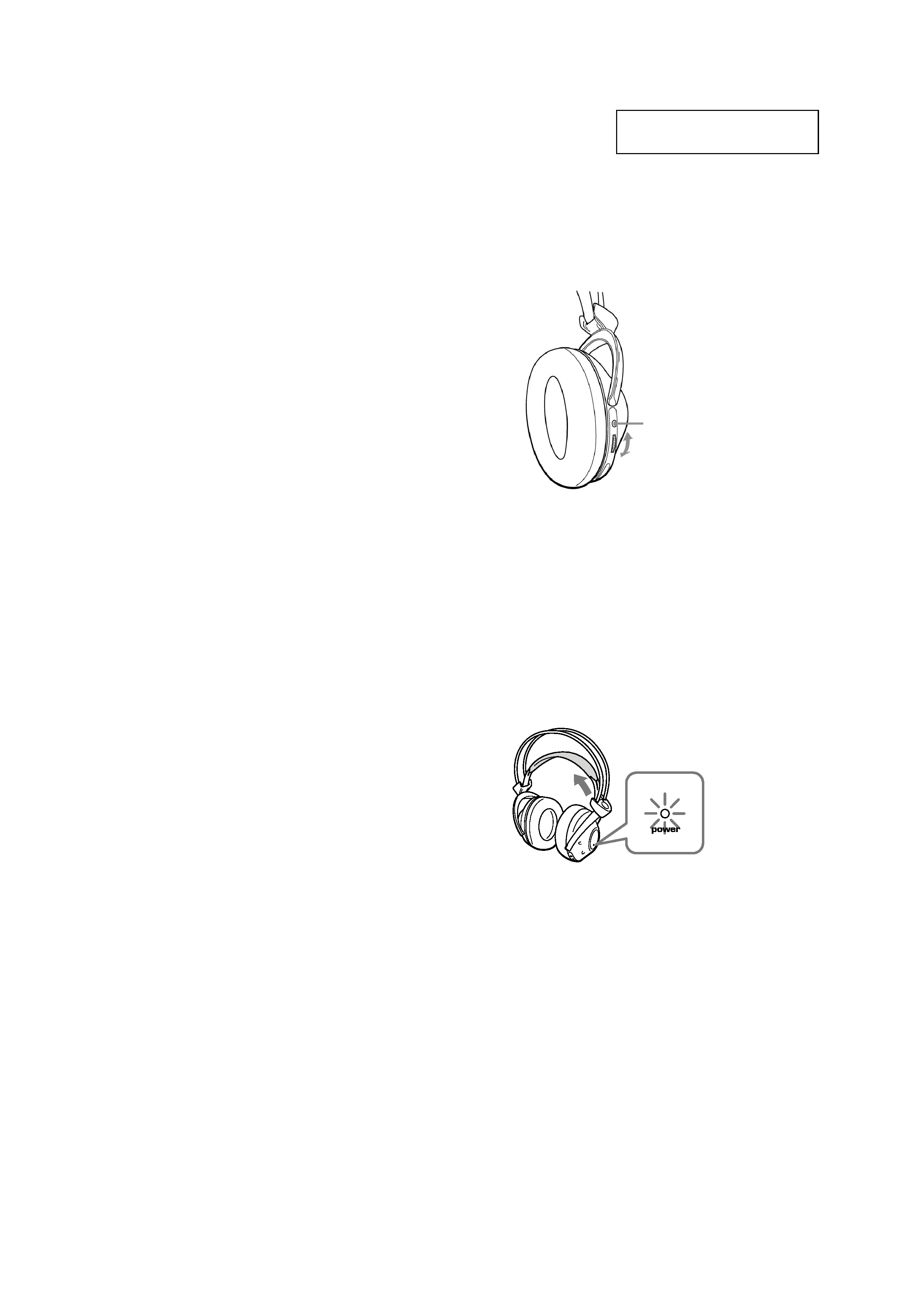
Auto power on/off function
When you remove the headphones from your
head, the power turns off automatically. Do not
allow the self adjusting band to be pulled up,
otherwise the headphones will be switched on.
The power turns on.
5 Turn up the volume to a moderate level
with the VOL control.
Press the TUNING button briefly for
automatic tuning of the headphones.
If you do not receive a clear audio signal,
press it again.
Try the above steps 3 and 5 until the
receiving performance becomes better.
TUNING
button
VOL control
TABLE OF CONTENTS
Specifications ............................................................................ 1
1.
GENERAL ......................................................................... 2
2. DISASSEMBLY
2-1. Driver (R Side), RX-BASE Board ........................... 3
2-2. SW Board, Hanger (R) ............................................. 4
2-3. Holder (R) ................................................................. 4
2-4. Driver (L Side) .......................................................... 5
2-5. Hanger (L) ................................................................ 6
2-6. Holder (L) ................................................................. 6
3. ELECTRICAL ADJUSTMENTS
3-1. Free Run Frequency Check and Adjustments ........... 7
3-2. Receive Frequency Check and Adjustments ............ 7
3-3. Carrier Modulation Check ........................................ 7
3-4. Expander Output Check ............................................ 7
3-5. Separation Check ...................................................... 7
4. DIAGRAMS
4-1. Block Diagrams ....................................................... 11
4-2. Schematic Diagram ................................................. 12
4-3. Printed Wiring Board .............................................. 13
5. XPLODEDVIEWS....................................................... 14
6. ELECTRICAL PARTSLIST..................................... 15
3
MDR-RF975R
SECTION 2
DISASSEMBLY
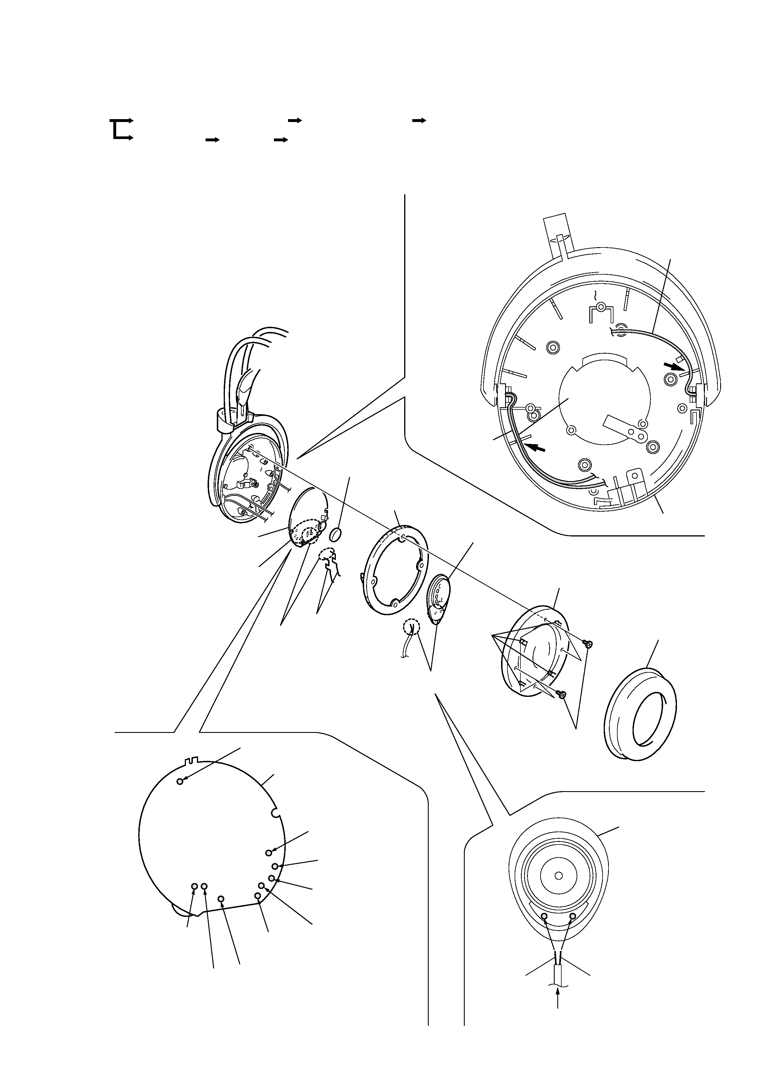
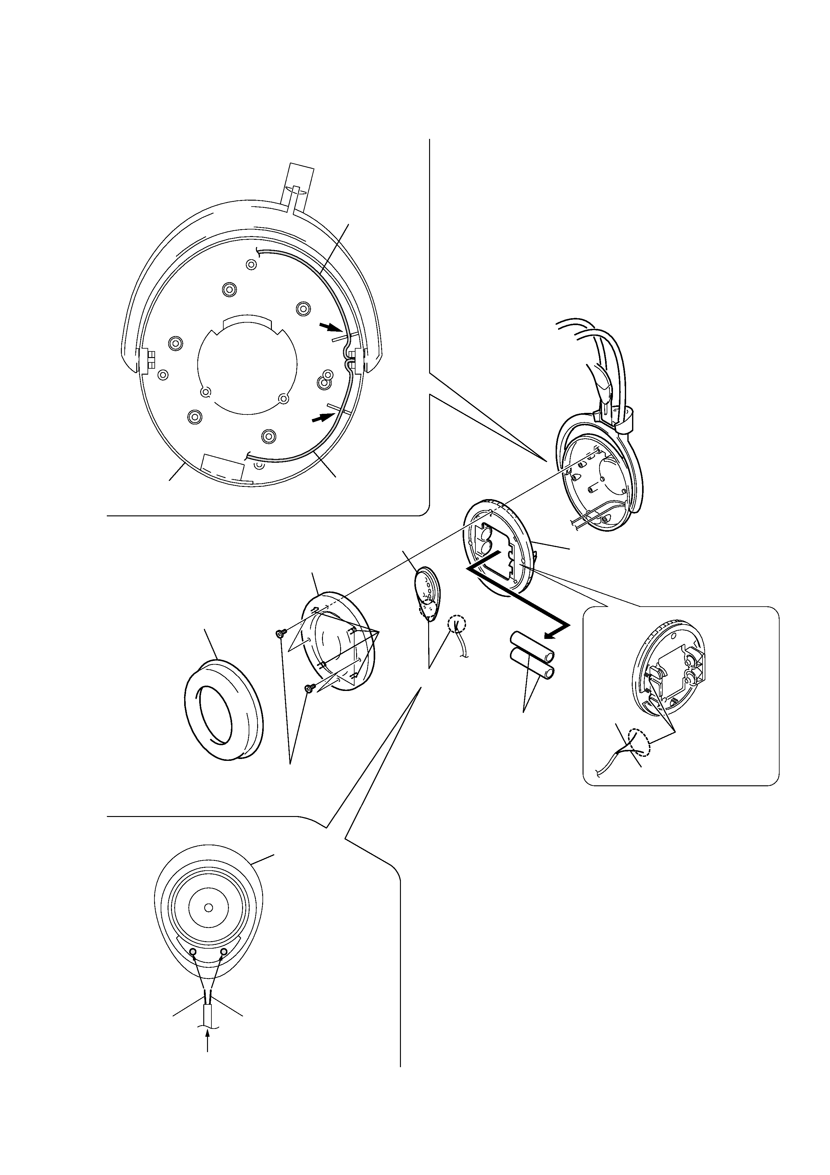
2-1. DRIVER (R SIDE), RX-BASE BOARD
· The equipment can be removed using the following procedure .
Driver (R side), RX-BASE board
Driver (L side),
Hanger (L)
Set
SW board, Harger (R)
Holder (L)
Holder (R)
Note: Follow the disassembly procedure in the numerical order given .
Four
claws
RX-BASE board
SW board
SW board
(Housing (R) side)
Housing (R)
Solder the each leads directly to the position as shown
while being cautions of colors.
Set the each leads as illustrated below.
Precaution for installtion
Precaution for installtion
Precaution for installtion
Head band
assy (front)(natural)
Head band
assy (front)(red)
Head band
assy (rear)(green)
Head band
assy (rear)(natural)
Driver (red)
Driver (natural)
Red
Natural
From RX-BASE board.
From head
band assy (front).
From head
band assy (rear).
From
SW board.
Driver (R side)
ANT
qa
RX-BASE board
0
Remove the
eight solderings.
2
Four screws (M 2
× 5)
1
pad, ear
4
Holder (R),ear pad
3
Plate (R) assy, front
6
Driver
8
Charge terminal
9
Volume knob
5
Remove the
two solderings.
7
Remove the
two solderings.
Groove
Groove
4
MDR-RF975R
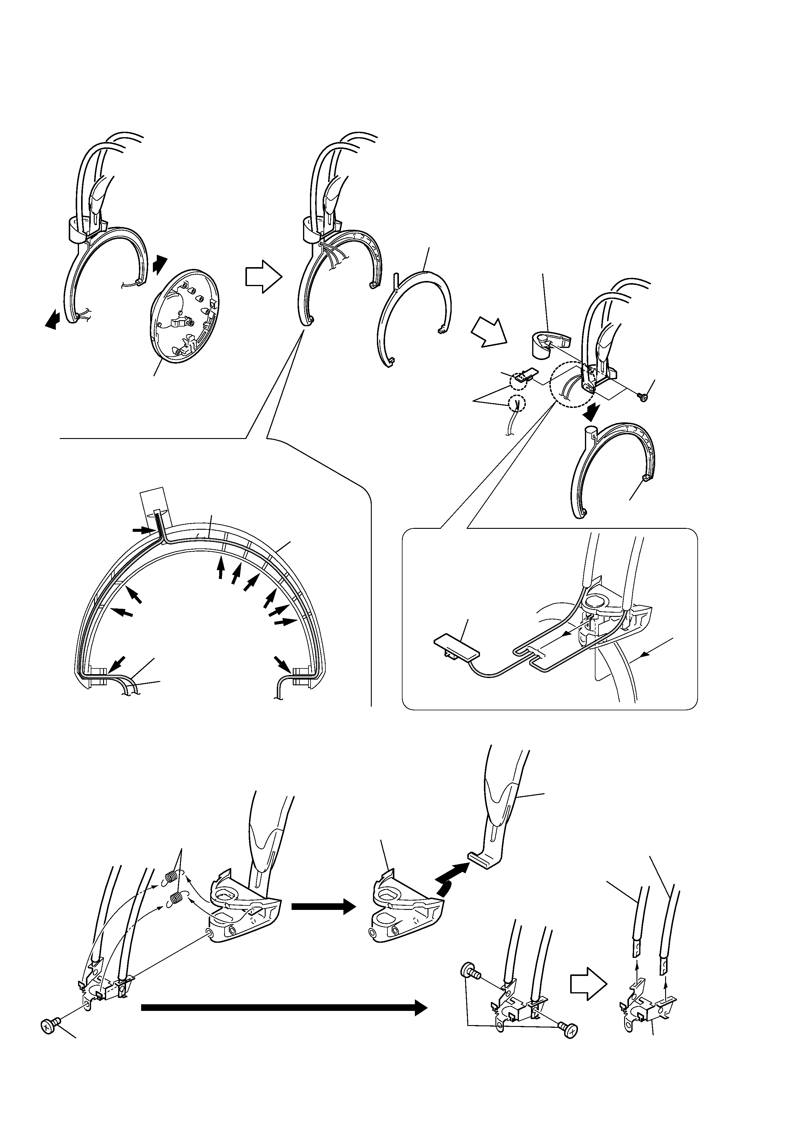
2-3. HOLDER (R)
2
Housing (R)
5
Holder (R)
3
Holder (R)
8
SW board
SW board
3
Lid (R), hanger
9
Hanger (R)
Hanger (R)
1
1
Precaution for installtion
Set the each leads as illustrated below.
7
Remove the
two solderings.
4
Two screws
(P 2
× 8)
1
Screw (P 2
× 8)
2
Spring
(ON/OFF)
4
Cushion assy, head
6
Chassis
5
Two screws
(P 2
× 8)
7
Band assy (rear), head
8
Band assy (front), Head
From head
band assy (front).
From head
band assy (rear).
From
SW board.
Groove
Groove
Groove
Groove
Groove
Groove
6
2-2. SW BOARD, HANGER (R)
5
MDR-RF975R
2-4. DRIVER (L SIDE)
Housing (L)
Set the each leads as illustrated below.
Precaution for installtion
Precaution for installtion
Green
Natural
Green
Natural
From head band assy (rear).
From head
band assy (front).
From head
band assy (rear).
Driver (L side)
2
Four screws (M 2
× 5)
1
Pad, ear
6
Ear pad
holder (L)
3
Plate (L) assy, front
8
Driver
Four
claws
7
Remove the
two solderings.
4
Two "batterys,
nickle hydrogen"
5
Remove the
two solderings.
Groove
Groove