MDR-RF830
UK Model
SERVICE MANUAL
WIRELESS STEREO HEADPHONES
MICROFILM
SPECIFICATIONS
MDR-RF830 is the component model block one in the MDR-RF830RK.
COMPONENT MODEL NAME FOR MDR-RF830RK
Power source
DC 3 V: 2
× R6 (size AA) battery
or 2
× supplied
NC-AA-HJ Ni-Cd
rechargeable battery
Mass
Approx. 215 g (7.6 oz.) incl.
Ni-Cd batteries
Design and specifications are subject to change
without notice.
Wireless Stereo Headphones
MDR-RF830
Transmitter
TMR-RF830R
Ver 1.0 1998.07
-- 2 --
Note: Follow the disassembly procedure in the numerical order given.
SECTION 1
DISASSEMBLY
-- 2 --
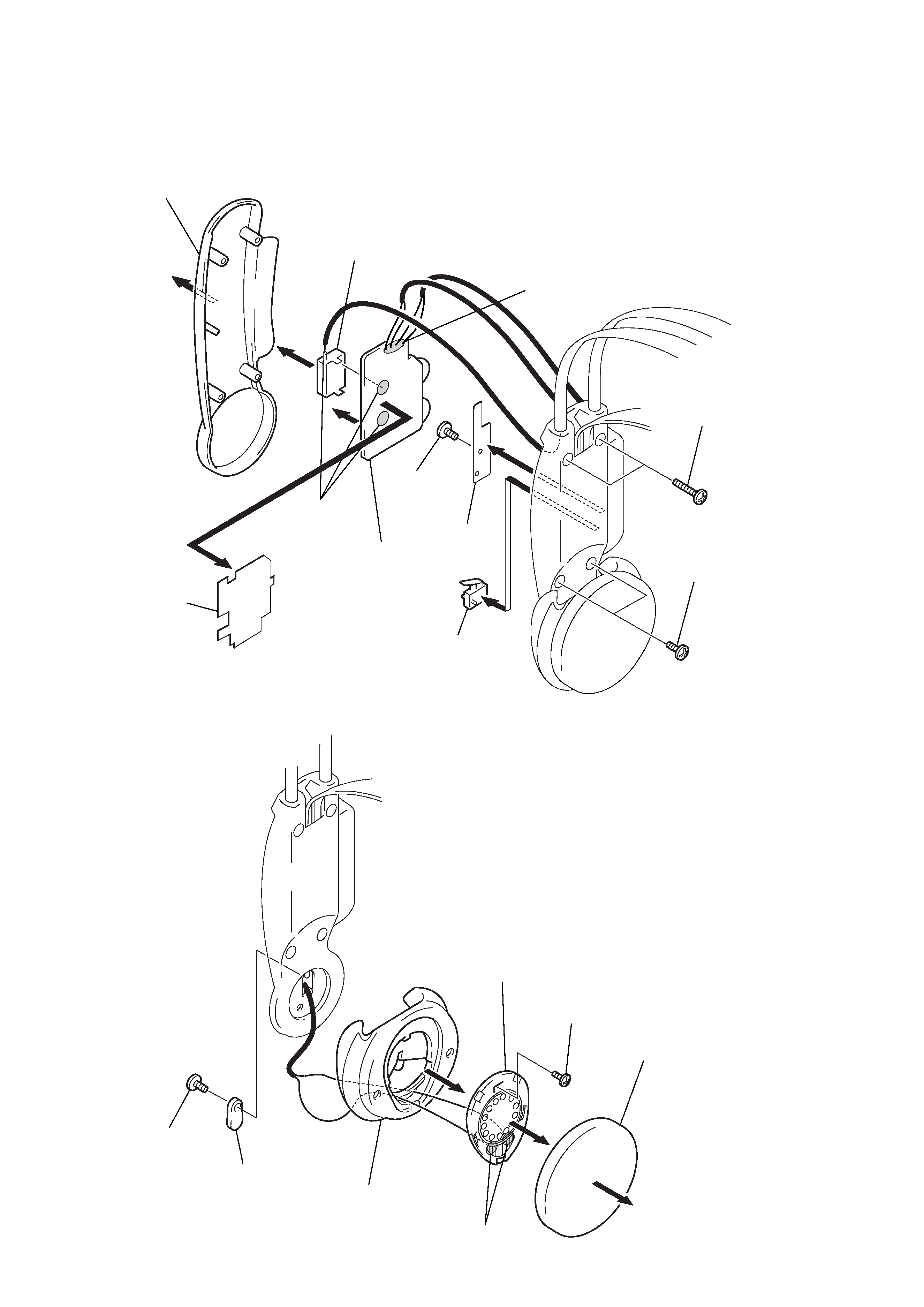
1-1. RX BOARD, FE BOARD (R-CH)
3 Cover (R), hanger
7 FE board
4 RX board
8 Remove solder
9 Screw
(M1.7
× 4)
1 Screws (+P2
× 12)
2 Screws (+P2
× 8)
0 Spacer
!¡ SW1
6 Remove
solder
5 Plate, RX shield
1-2. MDD02 (R-CH)
5 Screw (M1.7
× 4)
2 Screw (+P2
× 8)
4 Housing (R) assy
6 MDD02 (R-CH)
1 Pad, ear
7 Remove solder
3 Holder, ball shaft
-- 3 --
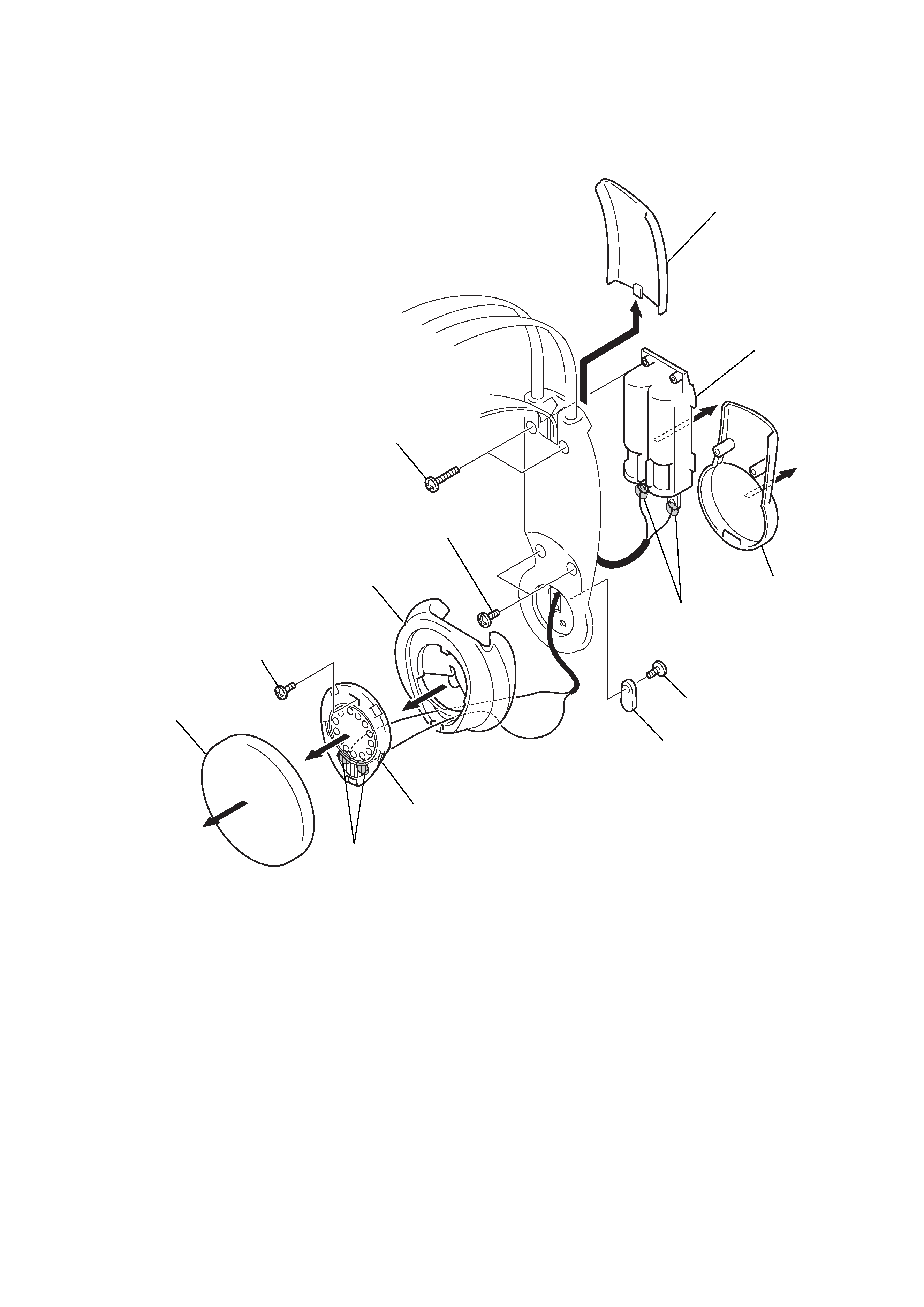
1-3. CASE, BATTERY, MDD01 (L-CH)
5 Screws (+P2
× 12)
3 Screws (+P2
× 8)
8 Screw (+P2
× 8)
!¡ Screw (M1.7
× 4)
0 Housing (L) assy
1 Pad, ear
!TM MDD01 (L-CH)
!£ Remove solder
9 Holder, ball shaft
7 Remove solder
4 Cover (L), hanger
6 Case, battery
2 Cover, battery

-- 4 --
Notes:
1.
Use transmitter with check and adjustment alreadycompleted.
2.
The transmitter section adjustments should be completed before
performing the headphones section adjustment.
3.
On adjusting the headphones section, use the transmitter as a jig.
Procedure:
1. Feed a signal to jig (transmitter) and connect a power supply to
DC IN
9V jack (J404).
Receive frequency check and adjustment
1. Set the transmitter channel to CH2.
2. Set the transmitter noise filter SW to OFF .
3. Input a signal of 1kHz 316mVrms to onl y the transmitter L-
CH (J403).
4. Place transmitter and headphones at a distance of more than 5m
apart.
5. Set the VOL (RV301) to MIN.
6. Position RX board TUNING VOL (RV302) to the center .
7. Connect a digital voltmeter (DC range) and an oscilloscope
between
IC301 pin @¡ and GND.
8. First check to make sure that a demodulated waveform of 1kHz
(appr oximately 13mVrms) is outputted to the oscilloscope ,
then
check to make sure the DC voltmeter reading is DC 1 to 1.2V .
9. If a demodulated waveform of 1kHz is not outputted to the
oscilloscope or if the DC level is not within the range specified
above, adjust the RX board L301 so that a demodulated
waveform of 1kHz is outputted to the oscilloscope and while
the wave-form is outputted, further fine adjust the L301 so that
the DC voltmeter reading is DC1.1V.
10. When completed, make sure signals can be received when
switching the transmitter channel to CH1 or CH3 by turning
RX board TUNING VOL (RV302).
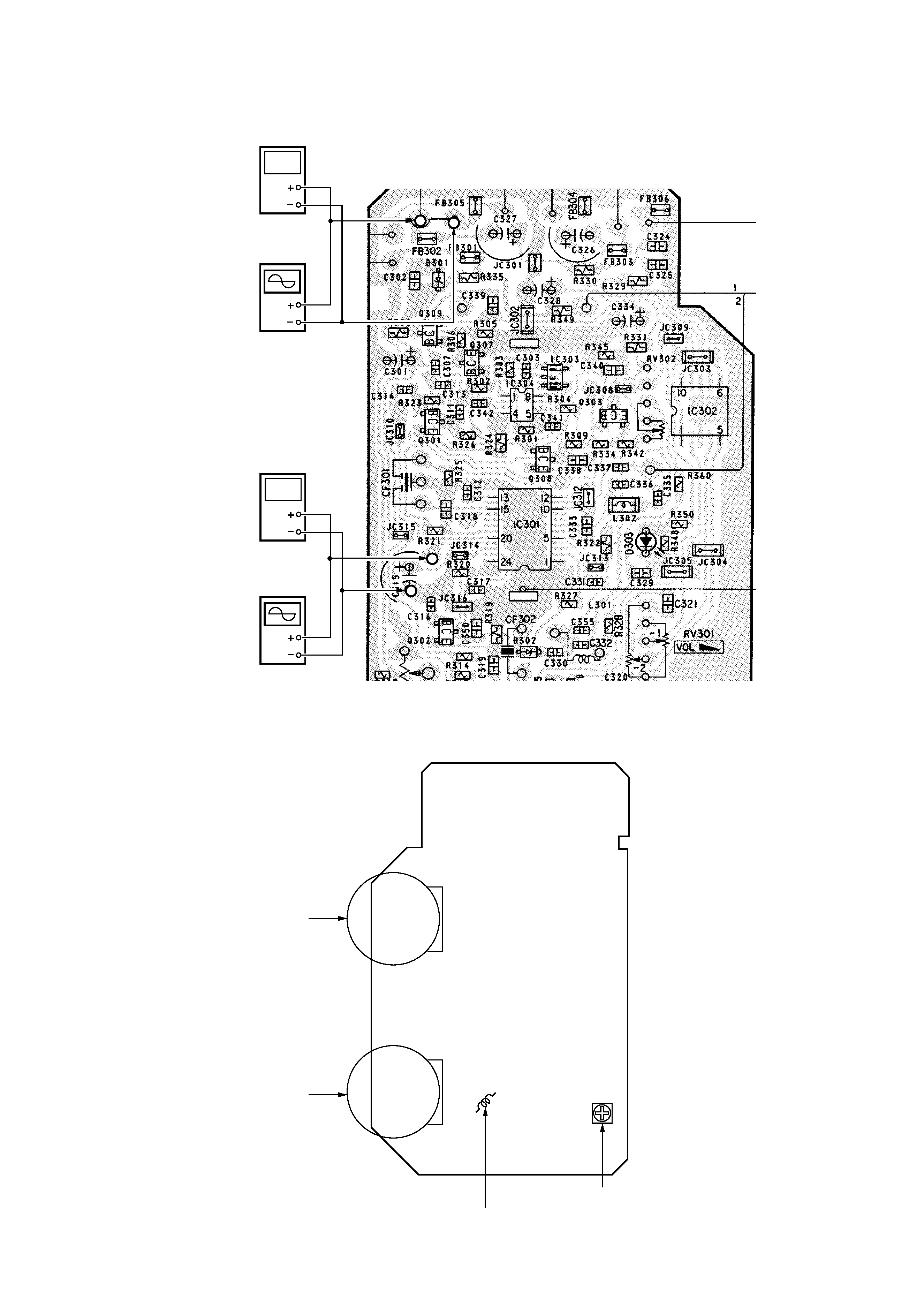
Connection points and Adjustment Location:
RX
BOARD (See page 5)
Separation check and adjustment
1. Set the transmitter channel to CH2.
2. Set the transmitter noise filter SW to OFF .
3. Input a signal of 1kHz 316mVrms to onl y the transmitter L-
CH (J403).
4. Connect an digital voltmeter (AC range) and oscilloscope to
the L-CH speaker outputs (both sides of MDD01).
5. Receive signals by turning the TUNING VOL (RV302).
6. Adjust the VOL (RV301) so that the RX board L-CH speaker
outputs (both sides of MDD01) are 155mVrms.
7. Connect an digital voltmeter (AC range) and oscilloscope to
the R-CH speaker outputs (both sides of MDD02) and measure
the voltages.
8. At this time, check to make sure the level separation of L-CH
and R-CH speaker outputs is more than 20dB. If the separation
is less than 20dB, turn R V303 on the RX boar d so that the R-
CH output is minimal, then check to see if the level separation
of L-CH and R-CH speaker outputs is more than 20dB.
9. Input a signal of 1kHz 316mVrms to only the transmitter R-CH
(J402).
10. Adjust the VOL (RV301) so that the RX boar d R-CH speaker
outputs (both sides of MDD02) are 155mVrms.
11. Connect an digital voltmeter (AC range) and oscilloscope to
the L-CH speaker outputs (both sides of MDD01) and measure
the voltages.
12. At this time, check to make sure the level separation of L-CH
and R-CH speaker outputs is more than 20dB.
Connection points and Adjustment Location:
RX BOARD (See page 5)
SECTION 2
ELECTRICAL ADJUSTMENTS
Headphones
MDR-RF830
Transmitter
TMR-RF830R
Transmitter
J404
power supply
(DC 9V)
L-CH (J403)
1kHz 316mVrms (7.8dB)
AF OSC
ATT
Jig
600
-- 5 --
Connection points :
Adjustment Location :
[ RX BOARD ] (Conductor side)
Oscilloscope
Digital voltmeter
(AC range)
Oscilloscope
Digital voltmeter
(DC range)
RV302
Tuning Knob
RV301
VOL Knob
L301 : Receive Frequency Adjustment
RV303 : Separation Adjustmen
t
[RX BOARD] (Component side)