1
SERVICE MANUAL
US Model
Canadian Model
E Model
Tourist Model
MDR-IF540R
HEADPHONES
Ver 1.0 2003. 03
9-877-225-01
2003C0400-1
© 2003. 03
Sony Corporation
Personal Audio Company
Published by Sony Engineering Corporation
Notes on Chip Component Replacement
· Never reuse a disconnected chip component.
· Notice that the minus side of a tantalum capacitor may be
damaged by heat.
Headphones
Power source
Supplied rechargeable
nickel-metal hydride
batteries BP-HP550 or
commercially available
(size AAA) dry batteries
Mass
Approx. 285 g (11 oz.)
including batteries
Design and specifications are subject to change without
notice.
SPECIFICATIONS
SRS is a trademark of SRS Labs Inc.
SRS Headphones are manufactured under
license from SRS Labs. Inc.
· The MDR-IF540R is the headphones
that comprises the MDR-IF540RK.
· MDR-IF540RK consists of the following models respectively.
Headphones
MDR-IF540R
Transmitter
TMR-IF540R

2
TABLE OF CONTENTS
1. GENERAL
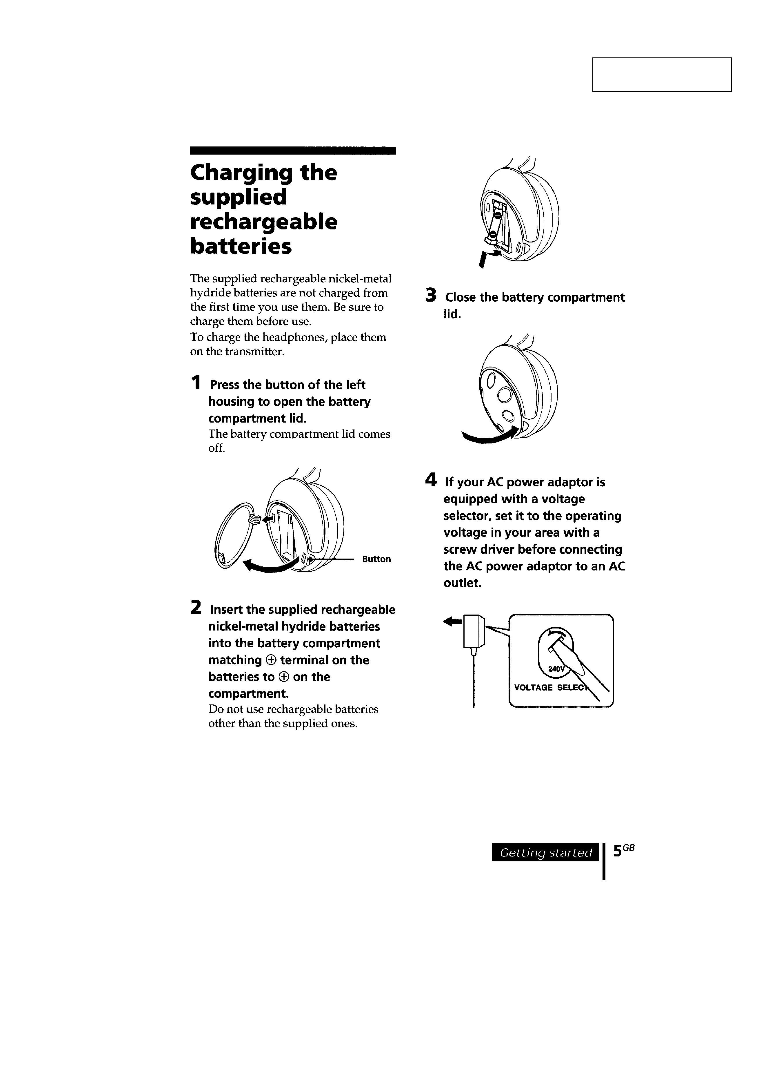
Charging the supplied rechargeable batteries .......................... 3
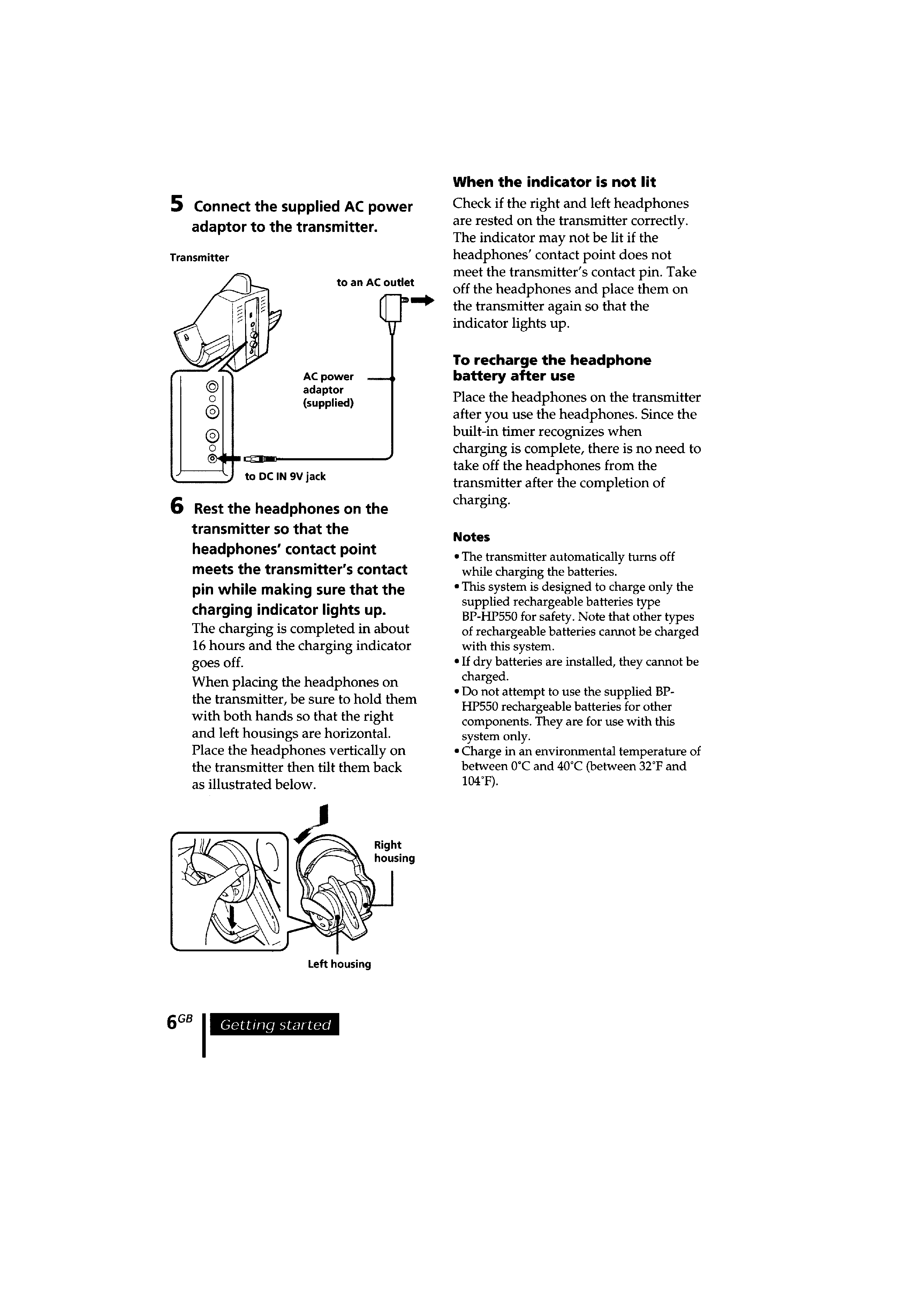
Listening to a programme ........................................................ 6
2. DISASSEMBLY
2-1. Front Plate (R) Assy ............................................................ 8
2-2. RX Board ............................................................................ 9
2-3. Hanger (R) ........................................................................... 9
2-4. Wiring on the Right Side ................................................... 10
2-5. Front Plate (L) Assy .......................................................... 10
2-6. BATT Board ...................................................................... 11
2-7. Hanger (L) ......................................................................... 11
2-8. Wiring on the Left Side ..................................................... 12
2-9. Hanger Lid (L) .................................................................. 12
2-10. Wiring on the SW Board ................................................... 13
2-11. Hang the Tension Spring ................................................... 13
3. ELECTRICAL ADJUSTMENTS
Tuning Adjustment ................................................................ 14
Mute ON Position Adjustment .............................................. 14
4. DIAGRAMS
4-1. Circuit Boards Location .................................................... 16
4-2. Block Diagram Receiver Section ................................ 17
4-3. Printed Wiring Boards Receiver Section (1/2) ............ 18
4-4. Printed Wiring Board Receiver Section (2/2) .............. 19
4-5. Printed Wiring Boards Power Section (1/2) ................ 20
4-6. Printed Wiring Board Power Section (2/2) ................. 21
4-7. Schematic Diagram Receiver Section ......................... 22
4-8. IC Block Diagrams ............................................................ 23
5. EXPLODED VIEWS
5-1. Housing (L) Assy Section ................................................. 24
5-2. Housing (R) Assy Section ................................................. 25
6. ELECTRICAL PARTS LIST ........................................ 26
MDR-IF540R
3
MDR-IF540R
SECTION 1
GENERAL
This section is extracted
from instruction manual.
4
MDR-IF540R
5
MDR-IF540R