-- 1 --
MDP-V70K
SERVICE MANUAL
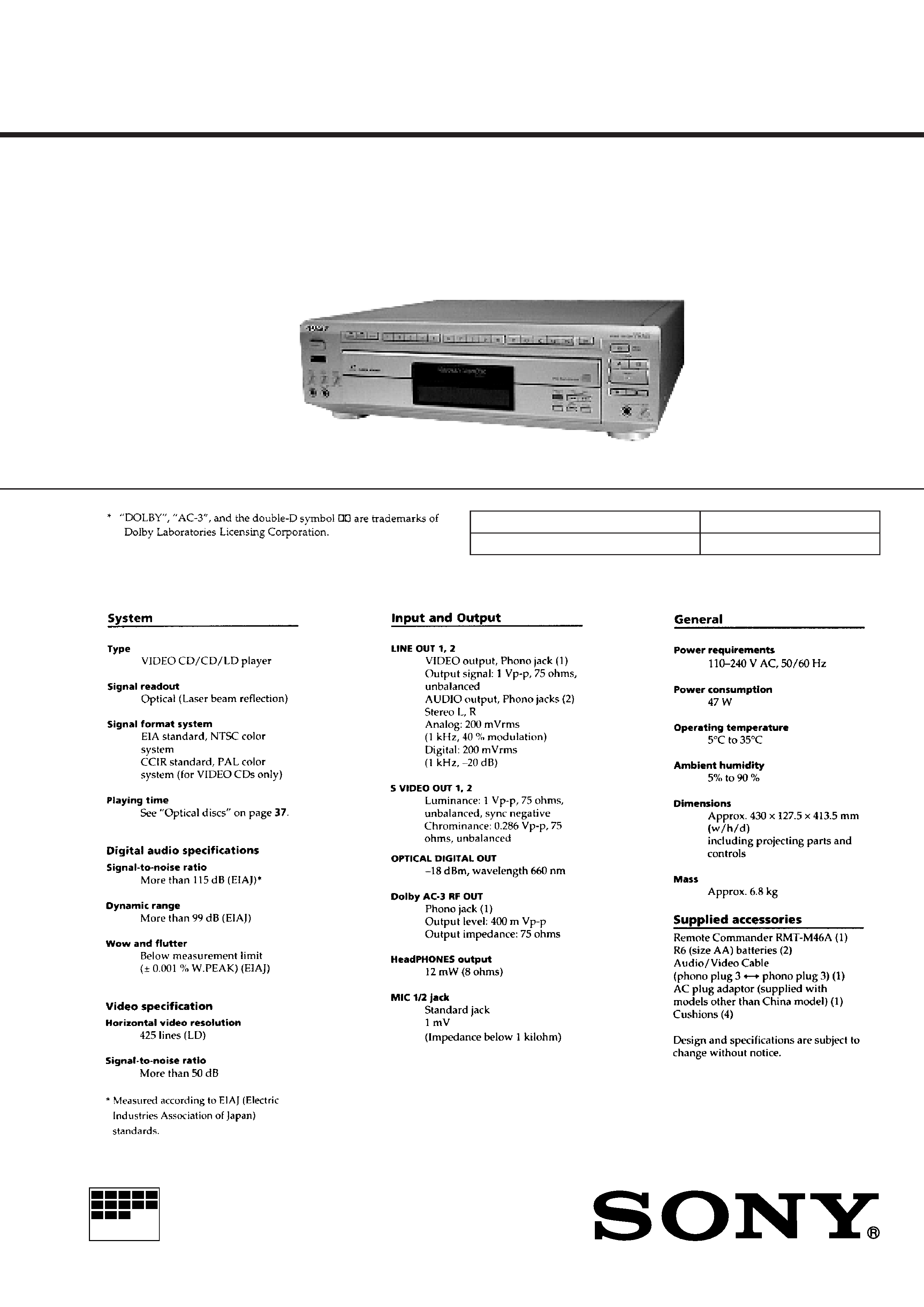
VIDEO CD/CD/LD PLAYER
MICROFILM
E Model
Chinese Model
RMT-M46A
Model Name Using Similar Mechanism
MDP-V1
Optical Pick-up Type
KHS-150A
SPECIFICATIONS
-- 2 --
MODEL IDENTIFICATION
-- BACK PANEL --
Parts No.
Parts No.
Model
3-971-070-6
3-971-070-7
E model
Chinese model
-- 3 --
Notes on chip component replacement
· Never reuse a disconnected chip component.
· Notice that the minus side of a tantalum capacitor may be
damaged by heat.
CAUTION
Use of controls or adjustments or performance of procedures
other than those specified herein may result in hazardous ra-
diation exposure.
SAFETY-RELATED COMPONENT WARNING !!
COMPONENTS IDENTIFIED BY MARK
!OR DOTTED LINE
WITH MARK
! ON THE SCHEMATIC DIAGRAMS AND IN
THE PARTS LIST ARE CRITICAL TO SAFE OPERATION.
REPLACE THESE COMPONENTS WITH SONY PARTS
WHOSE PART NUMBERS APPEAR AS SHOWN IN THIS
MANUAL OR IN SUPPLEMENTS PUBLISHED BY SONY.
-- 4 --
SYMPTOM
No error
Transmission error between
IC305 and IC101.
TABLE OF CONTENTS
1. GENERAL
Index to parts and controls ........................................................ 1-1
Playing a disc ............................................................................ 1-2
Playing a VIDEO CD using PBC functions (PBC Playback) ... 1-3
About on-screen indications ...................................................... 1-4
Selecting a chapter or track directly (Chapter/Track Search) .... 1-5
Searching by frame, time, or scene number
(Frame/ Time/Scene Search) ..................................................... 1-5
Searching for a particular point on a disc .................................. 1-6
Locating by observing several scenes at one time
(Digest Play) ............................................................................ 1-7
Viewing Frame-by-frame action ................................................ 1-8
Resuming LD/VIDEO CD playback (Auto Resume) ............... 1-8
Playing a section repeatedly (Repeat Play) ............................... 1-9
Playing songs in random order (Shuffle Play) ......................... 1-10
Playing songs in any order you like (Program Play) ............... 1-11
Playing a disc within a specified period of time
(Auto Program Play) ................................................................ 1-11
Using the sound control functions ........................................... 1-12
Reducing Distortion of the Picture
(DNR: Digital Noise Reduction) ............................................. 1-13
Playing Karaoke ...................................................................... 1-13
2. DISASSEMBLY
2-1. Opening of MB-97/VX-97 Board (Service Position) ........ 2-1
2-2. Front Panel Assembly ....................................................... 2-1
2-3. Disc Tray Assembly ........................................................... 2-2
2-4. Chucking Block Assembly ................................................. 2-2
2-5. Frame (L, R) Assembly ...................................................... 2-3
2-6. Mounting the Frame (R) Assembly .................................... 2-3
2-7. Control Gear and Loading Motor Assembly ...................... 2-4
2-8. Mounting the Control Gear ................................................ 2-4
2-9. Feed Base Block Assembly ................................................ 2-5
2-10. Mounting the Feed Base Block Assembly ....................... 2-6
2-11. Height Adjustment of the Turntable Assembly ................ 2-7
2-12. Optical Pick-up Block (KHS-150A)
Disassembly I
(Optical Pick-up Block Motor Operates) ......................... 2-7
Disassembly II
(Optical Pick-up Block Motor Operates) ......................... 2-8
Disassembly III
(Optical Pick-up Block Motor Doesn't Operate) ............. 2-8
2-13. Mounting the Optical Pick-up Block Assembly .............. 2-9
2-14. Circuit Boards Location ................................................. 2-10
3. BLOCK DIAGRAMS
3-1. Overall (1/3) Block Diagram ............................................. 3-1
3-2. Overall (2/3) Block Diagram ............................................. 3-3
3-3. Overall (3/3) Block Diagram ............................................. 3-5
3-4. Video (1/2) Block Diagram ................................................ 3-7
3-5. Video (2/2) Block Diagram ................................................ 3-9
3-6. Servo (1/2) Block Diagram .............................................. 3-11
3-7. Servo (2/2) Block Diagram .............................................. 3-13
3-8. System Control (1/2) Block Diagram .............................. 3-15
3-9. System Control (2/2) Block Diagram .............................. 3-17
3-10. Mode Control Block Diagram ....................................... 3-19
3-11. Audio (1/2) Block Diagram ............................................ 3-21
3-12. Audio (2/2) Block Diagram ............................................ 3-23
3-13. Video CD (1/2) Block Diagram ..................................... 3-25
3-14. Video CD (2/2) Block Diagram ..................................... 3-27
3-15. Power Block Diagram .................................................... 3-29
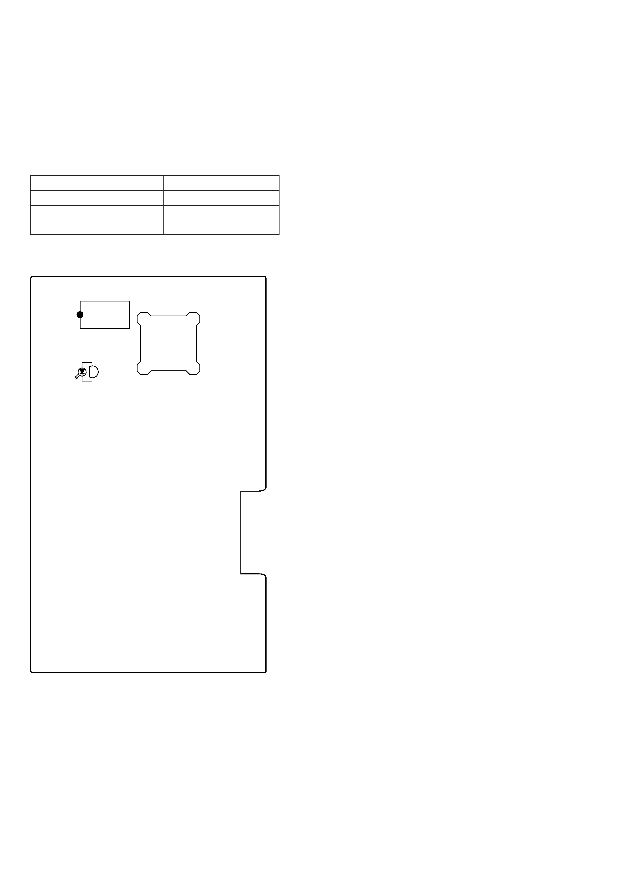
SERVICING NOTE
SELF-DIAGNOSIS
This model has the self-diagnosis function for the video and audio
decoder sections.
Immediately after the power on, the self-diagnosis function searches
each operation of IC's around the mode microcomputer (IC305).
The LED (D301) on the VX-97 board indicates their results.
[VX-97 BOARD] -- SIDE B --
IC305
IC301
D301
LED (D301) INDICATION
Light
1 time blinking (Repeatedly)

-- 5 --
4. PRINTED WIRING BOARDS AND SCHEMATIC
DIAGRAMS
4-1. Frame Schematic Diagram ................................................. 4-1
4-2. Printed Wiring Boards and Schematic Diagrams ............... 4-5
· MB-97 (Video, Servo, System Control, Audio) Board ... 4-7
· MB-97 (Video) Board ................................................... 4-11
· MB-97 (Servo, System Control) Board ........................ 4-16
· MB-97 (Audio) Board .................................................. 4-21
· VX-97 Board ................................................................ 4-25
· FP-1090 Board .............................................................. 4-33
· PW-1090, SW-1090A, SW1090B Boards .................... 4-40
· YC-97 Board ................................................................. 4-46
· HP-97 Board ................................................................. 4-49
· MA-1089 Board ............................................................ 4-51
· FG-42, IB-10, MD-67, MT-59, SW-278 Boards .......... 4-53
· PS-97, ST1090 Boards .................................................. 4-60
5. REPAIR PARTS LIST
5-1. Exploded Views ................................................................. 5-1
5-1-1. Upper Case and Front Panel Section ........................... 5-1
5-1-2. Main Chassis Section (1) ............................................. 5-2
5-1-3. Main Chassis Section (2) ............................................. 5-3
5-1-4. Frame (L, R) Section ................................................... 5-4
5-1-5. Mechanism Deck Section ............................................ 5-5
5-2. Electrical Parts List ........................................................... 5-6
6. IC PIN DESCRIPTION
6-1. Mode Control IC Pin Description
(FP-1090 Board IC102 HD6433712-C41H) ...................... 6-1
6-2. VCD Mode Control IC Pin Description
(VX-97 Board IC305 HD6413002F10) ............................. 6-2
6-3. System Control IC Pin Description
(MB-97 Board IC501 MB89094PF-G-154-BND) ............. 6-4
6-4. System Control IC Pin Description
(MB-97 Board IC502 LC21011B-X78) ............................. 6-6
7. ADJUSTMENTS
7-1. List of Servicing Jigs ......................................................... 7-1
7-2. Caution on Adjustment ...................................................... 7-1
7-3. Power Block Check ............................................................ 7-1
7-3-1. Power Supply Check (PS-97 board) ............................ 7-1
7-4. System Control System Adjustment .................................. 7-1
7-4-1. Microprocessor Clock Adjustment (MB-97 board) ..... 7-1
7-5. Adjustment After the Attachment of the Optical Pick-up
Block ................................................................................. 7-2
7-5-1. Jigs and Tools .............................................................. 7-2
7-5-2. CD Adjustment ............................................................ 7-2
7-6. Servo System Adjustments ................................................ 7-4
7-6-1. LD Side A Adjustment ................................................. 7-4
7-6-2. LD Side B Adjustment ................................................. 7-5
7-7. Video System Adjustments ................................................ 7-6
7-7-1. LD Output Level Adjustment (MB-97 board) ............. 7-6
7-7-2. Video Clock Adjustment (VX-97 board) ..................... 7-6
7-7-3. Video CD Output Level Adjustment
(VX-97 board) ............................................................. 7-6
7-8. Arrangement Diagram For Adjustment Parts ..................... 7-8
8. EVALUATION OF OPTICAL PICK-UP BLOCK
(KHS-150A)
8-1. Preparation ........................................................................ 8-1
8-2. RF Level Check ................................................................. 8-1
8-3. Tracking Level/Tracking Balance Check ........................... 8-1
8-4. Crosstalk Check ................................................................. 8-1
9. INSTRUCTION MANUAL FOR SPECIAL
FUNCTIONS ................................................................... 9-1
(For the contents of section 9, refer to page 9-1.)