SERVICE MANUAL
PERSONAL NETWORK PLAYER
AEP Model
SPECIFICATIONS
MC-S50
Ver 1.0 2001.03
9-873-098-11
Sony Corporation
2001C0500-1
Audio Entertainment Group
C
2001.3
General Engineering Dept.
Audio specifications
Frequency response
20 20,000 Hz
Signal-to-noise ratio (S/N)
85 dB
Memory capacity
64 MB (including the system software:
61.1 MB available for music)
Available file format
ATRAC3
MP3
Bit rate*: 32256 kbps
Sampling rate: 32/44.1/48 kHz
* Variable bit rate files are not
supported. Bit rate higher than 128
kbps is not guaranteed when you
select the sampling rate 32 or 48 kHz.
WMA**
Bit rate: 64160 kbps
**The files applied with the Microsoft
Windows Media Right Manage are
not supported.
Output
Headphones jack
Stereo mini jack
Connector (special mini jack)
USB 1.0 compliant
General
Power requirements
LR03 (Size AAA) alkaline battery
× 1
USB bus power
Battery life
Approx. 6 hours (varies depending on
bit rate, volume, etc.)
Operating temperature
5°C to 35°C (41°F to 95°F) (not
condensed)
Environment temperature
20°C to 60°C (4°F to 140°F) (not
condensed)
Supplied accessories
· LR03 (Size AAA) alkaline battery (1)
· Headphones (1)
· Headphones/earphones
extension cord (1)
· Neck strap (1)
· USB cable (1)
· CD-ROM (OpenMG Jukebox
installation disc) (1)
· MC-S50 Operating Instructions (1)
· OpenMG Jukebox Operating
Instructions
Design and specifications are subject to change
without notice.
(1)
Power consumption
Approx. 145 mW
Dimensions (approx.)
Approx. 22.4
× 99.0 × 25.9 mm (29/
32
× 4
×1 inches) (w/h/d)
Mass
Approx. 33g (1.2 oz ) (including
battery)

2
MC-S50
TABLE OF CONTENTS
1.
SERVICING NOTES .................................................. 3
2.
GENERAL ...................................................................... 9
3.
DISASSEMBLY
3-1. Disassembly Flow ............................................................ 10
3-2. Case Assy, Upper ............................................................. 10
3-3. Power Board ..................................................................... 11
3-4. "LOGIC Board", "AUDIO Board",
"FLEXIBLE (JACK) Board, Jack (J301)" ...................... 11
3-5. "LOGIC Board",
"Display Panel, Liquid Crystal (LCD901)" .................... 12
4.
DIAGRAMS
4-1. Block Diagram ................................................................. 13
4-2. Note for Printed Wiring Boards and
Schematic Diagrams ........................................................ 14
4-3. Printed Wiring Board LOGIC Board ........................ 14
4-4. Schematic Diagram LOGIC Board .......................... 15
4-5. Printed Wiring Board AUDIO Board ....................... 16
4-6. Schematic Diagram AUDIO Board .......................... 17
4-7. Printed Wiring Board POWER Board ...................... 18
4-8. Schematic Diagram POWER Board ......................... 19
4-9. IC Pin Function Description ............................................ 22
5.
EXPLODED VIEWS
5-1. Upper Case Assy .............................................................. 26
5-2. Board Assy ....................................................................... 27
6.
ELECTRICAL PARTS LIST ................................ 28
Flexible Circuit Board Repairing
· Keep the temperature of the soldering iron around 270 °C dur-
ing repairing.
· Do not touch the soldering iron on the same conductor of the
circuit board (within 3 times).
· Be careful not to apply force on the conductor when soldering
or unsoldering.
Notes on chip component replacement
· Never reuse a disconnected chip component.
· Notice that the minus side of a tantalum capacitor may be dam-
aged by heat.
UNLEADED SOLDER
Boards requiring use of unleaded solder are printed with the lead-
free mark (LF) indicating the solder contains no lead.
(Caution: Some printed circuit boards may not come printed with
the lead free mark due to their particular size)
: LEAD FREE MARK
Unleaded solder has the following characteristics.
· Unleaded solder melts at a temperature about 40 °C higher than
ordinary solder.
Ordinary soldering irons can be used but the iron tip has to be
applied to the solder joint for a slightly longer time.
Soldering irons using a temperature regulator should be set to
about 350 °C .
Caution: The printed pattern (copper foil) may peel away if the
heated tip is applied for too long, so be careful!
· Strong viscosity
Unleaded solder is more viscous (sticky, less prone to flow) than
ordinary solder so use caution not to let solder bridges occur
such as on IC pins, etc.
· Usable with ordinary solder
It is best to use only unleaded solder but unleaded solder may
also be added to ordinary solder.
Sony, VAIO, the VAIO logo, Music Clip, OpenMG
and the OpenMG logo are trademarks of Sony
Corporation.
Microsoft, Windows, Windows NT, Windows
Media, Windows Millennium Edition and their
logos are trademarks or registered trademarks of
Microsoft Corporation in the United States and/or
other countries.
US and foreign patents licensed from Dolby
Laboratories.
All other trademarks and registered trademarks are
trademarks or registered trademarks of their
respective holders.

3
MC-S50
1-1.
Introduction
This document describes the "operation check for inspection (Test mode)" and "adjustment after board replacement for repair".
In performing these works, connect this set to the PC via a USB cable and use the following tool.
Tool list
Ref. No.
Tool name
Part code
Application
1
Service Tool 9140 (FD)
J-2507-037-1
Board check (Test mode) and readjustment after board replacement
1-2.
Board Repair
1. In performing the work, the set should be in a complete state (all components assembled).
2. Install the "OpenMG Jukebox" and "WMP7 Plug-in" (CD-ROM) in the PC in advance.
3. Do not start up other applications in the PC.
4. This set has the Test mode, and the use of exclusive application (Service Tool) on the PC side enables various function checks and the
voltage adjustment.
5. For the LOGIC board in this set, if either part listed in Table 1 is faulty, be sure to replace the board block. Also, when a part on the
POWER board was replaced or a combination of LOGIC board and POWER board was changed due to the board replacement,
perform 1-5 "Adjustment When Board was Replaced/Repaired".
6. The data in Table 1-2 have been written to the LOGIC board.
7. In repairing other than above parts, repair as usual.
Table 1-1.
Board name
Ref. No
LOGIC board
IC601, IC602, IC603, IC901
Table 1-2.
Board name
Stored data
LOGIC board
Music data, Battery adjustment value, Equalizer initial values, CODEC programs, and ID/IK codes
1-3.
Operation Check for Inspection (Test Mode)
Precautions
1. Be sure to remove the battery from this set. (The power is supplied via USB cable)
Operating the set in the Test mode with the battery loaded could clear necessary information.
2. If operation check was performed for inspection, execute "Play Info Initialize" in qd (see page 7) to return respective functions to
initial positions (see Table 1-5 on page 7). In such a case, record current position of each function before executing "Play Info
Initialize" in qd, if necessary.
SECTION 1
SERVICING NOTES
4
MC-S50
Work procedure
Preparation:
1. Make sure that no battery is loaded in the set.
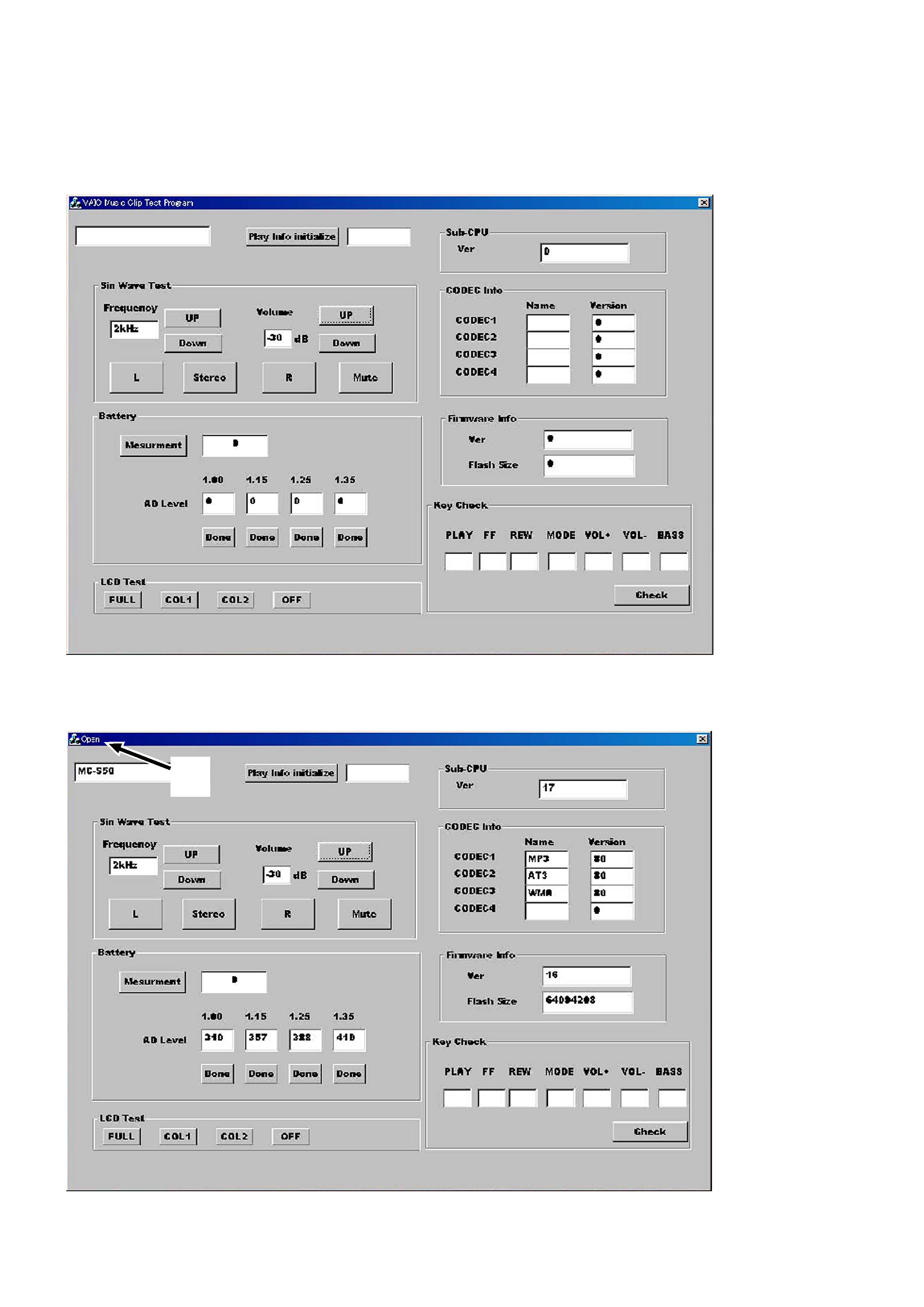
2. Start up the test mode "apollo_service.exe" of the service tool (J-2507-037-1) from the PC, and check that the following screen
appears.
3. Connect PC to this set with a USB cable. Check that the block 1 of the following screen "open", and "1PC" is displayed on the LCD
of the set. (The block 1 will "close" if the set is disconnected again)
At this time, a sine wave is outputted from the headphone. Also, the model name is displayed in the block qd of the screen.
Note: If the block 1 does not "open", the circuits in LOGIC board will be faulty. Audio signals are outputted from the reference signal in the DSP of
the set.
1
5
MC-S50
Operational description of Test mode
1.
Audio Block Function Check
Clicking the UP or Down button in block 2 of the screen allows you to check with various output frequencies. Also, clicking the UP or
Down button in block 3 can check variations of volume. Clicking the L, Stereo, R, or Mute button in block 4 can change audio output
status.
2.
Battery Threshold Value Reading and Measurement
Connect an exclusive USB cable to the set, and available battery threshold values (converted values corresponding to voltage values)
written to the set at the shipment will be displayed at 5. (See Table 1-3)
These threshold values are inherent values of the set, but if they were readjusted during the board repair, newly set threshold values
(converted values corresponding to voltage values) are displayed.
Table 1-3.
Condition
OFF
Scale 1
2
Scale 2
3
Scale 3
4
Voltage set value
1.00 V
1.15 V
1.25 V
1.35 V
Converted value (ref.)
320
368
400
432
Note: The threshold values (converted values corresponding to voltage values) are different every set.
3.
LCD Test
Clicking FULL (full lit), COL1 (column 1), COL2 (column 2), or OFF (full off) in block 8 results in all ON, column 1 ON, column 2 ON,
or all OFF of the LCD on the set respectively.
4.
CODEC Info Check
The CODEC programs and their versions written to the set can be checked. (block 9)
The CODEC programs written to the set at the shipment are "MP3", "ATRAC3", and "WMA" and their versions are as listed below.
(Versions will vary if updated)
Program No.
Name
Version
CODEC1
MP3
96
CODEC2
AT3
96
CODEC3
WMA
96
CODEC4
blank
0
qd
2
3
4
6
5
8
qs
0
9
qa
7