# No.
DATA
CONTENTS
#1
2000.3
Alteration of parts supply, as the service division had changed. (P.6-2)
MODEL NAME : MCM-21T2
SERVICE MANUAL
PARTS No. : 9-978-673-01
MODIFICATION
HISTORY
* Blue characters are linking.
CHASSIS
SERVICE MANUAL
SPECIFICATIONS
MCM-21T2
G1
AEP Model
Chassis No. SCC-L22M-A
COLOR MONITOR
CRT
0.24 mm aperture grille pitch
21 inches measured diagonally
90-degree deflection
FD Trinitron
Viewable image size
Approx. 403.8
× 302.2 mm (w/h)
(16
× 12 inches)
19.8" viewing image
Recommended resolution Horizontal: 1600 dots
Vertical: 1200 lines
Standard image area
Approx. 388
× 291 mm (w/h)
(15 3/8
× 11 1/2 inches)
or
Approx. 364
× 291 mm (w/h)
(14 3/8
× 11 1/2 inches)
Deflection frequency*
Horizontal: 30 to 121 kHz
Vertical: 48 to 160 Hz
AC input voltage/current
100 to 240 V, 50 60 Hz, 2.0 1.0 A
Power consumption
Approx. 145 W
Dimensions
Approx. 498
× 491 × 478 mm (w/h/d)
(19 5/8
× 19 3/8 × 18 7/8 inches)
Mass
Approx. 32 kg (70 lb 9 oz)
Plug and Play
DDC1/2B/2Bi, GTF**
* Recommended horizontal and vertical timing condition
· Horizontal sync width duty should be more than 4.8% of total
horizontal time or 0.8
µs, whichever is larger.
· Horizontal blanking width should be more than 2.3
µsec.
· Vertical blanking width should be more than 450
µsec.
** If the input signal is Generalized Timing Formula (GTF)
compliant, the GTF feature of the monitor will automatically
provide an optimal image for the screen.
Design and specifications are subject to change without notice.
MCM-21T2
2
LEAKAGE TEST
The AC leakage from any exposed metal part to earth ground
and from all exposed metal parts to any exposed metal part hav-
ing a return to chassis, must not exceed 0.5 mA (500 microam-
peres).
Leakage current can be measured by any one of three methods.
1. A commercial leakage tester, such as the Simpson 229 or
RCA WT-540A. Follow the manufacturers' instructions to
use these instruments.
2. A battery-operated AC milliammeter. The Data Precision
245 digital multimeter is suitable for this job.
3. Measuring the voltage drop across a resistor by means of a
VOM or battery-operated AC voltmeter. The "limit" indica-
tion is 0.75 V, so analog meters must have an accurate low-
voltage scale. The Simpson 250 and Sanwa SH-63Trd are
examples of a passive VOMs that are suitable. Nearly all
battery operated digital multimeters that have a 2 V AC
range are suitable. (See Fig. A)
After correcting the original service problem, perform the fol-
lowing safety checks before releasing the set to the customer:
1. Check the area of your repair for unsoldered or poorly-sol-
dered connections. Check the entire board surface for solder
splashes and bridges.
2. Check the interboard wiring to ensure that no wires are
"pinched" or contact high-wattage resistors.
3. Check that all control knobs, shields, covers, ground straps,
and mounting hardware have been replaced. Be absolutely
certain that you have replaced all the insulators.
4. Look for unauthorized replacement parts, particularly tran-
sistors, that were installed during a previous repair. Point
them out to the customer and recommend their replacement.
5. Look for parts which, though functioning, show obvious
signs of deterioration. Point them out to the customer and
recommend their replacement.
6. Check the line cords for cracks and abrasion. Recommend
the replacement of any such line cord to the customer.
7. Check the B+ and HV to see if they are specified values.
Make sure your instruments are accurate; be suspicious of
your HV meter if sets always have low HV.
8. Check the antenna terminals, metal trim, "metallized"
knobs, screws, and all other exposed metal parts for AC
Leakage. Check leakage as described below.
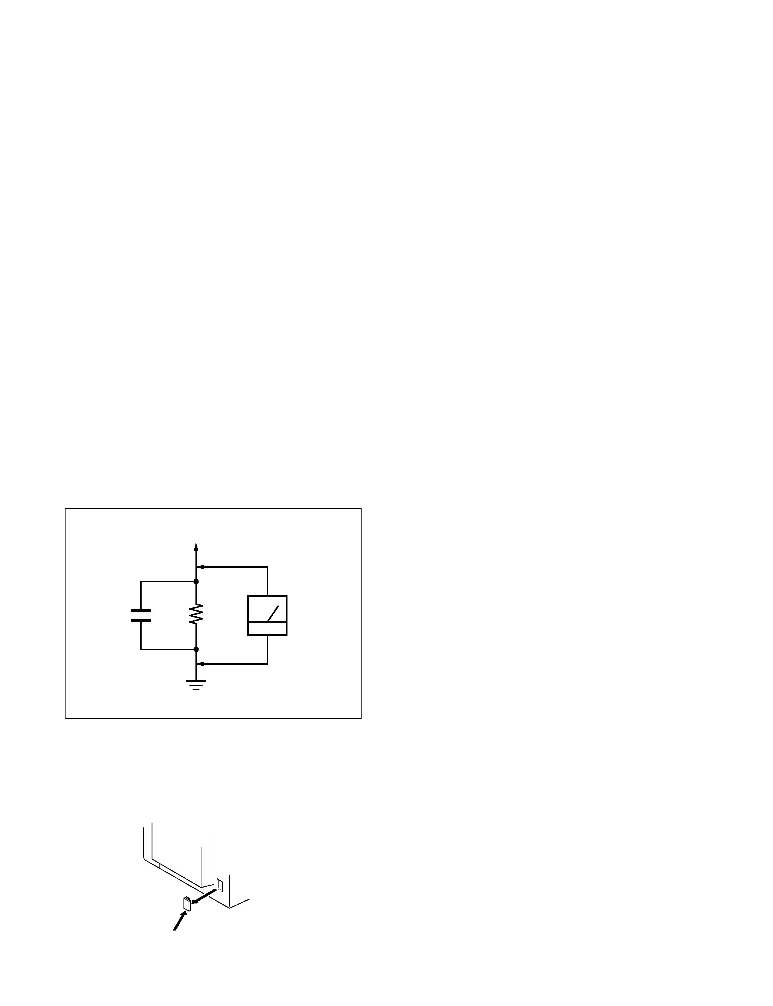
Fig. A. Using an AC voltmeter to check AC leakage.
SAFETY CHECK-OUT
1.5 k
0.15
µF
AC
Voltmeter
(0.75 V)
To Exposed Metal
Parts on Set
Earth Ground
CAUTION ON DAS (ECS) CONNECTOR
· The connector for DAS (ECS) adjustment is provided inside
the cover shown below. Be careful with an electrical shock
when connecting the connector with the power supplied. Also,
return the removed cover to the home position.
Cover ECS
Rear side
WARNING!!
NEVER TURN ON THE POWER IN A CONDITION IN
WHICH THE DEGAUSS COIL HAS BEEN REMOVED.
SAFETY-RELATED COMPONENT WARNING!!
COMPONENTS IDENTIFIED BY SHADING AND MARK
¡ ON THE SCHEMATIC DIAGRAMS, EXPLODED
VIEWS AND IN THE PARTS LIST ARE CRITICAL FOR
SAFE OPERATION. REPLACE THESE COMPONENTS
WITH SONY PARTS WHOSE PART NUMBERS AP-
PEAR AS SHOWN IN THIS MANUAL OR IN SUPPLE-
MENTS PUBLISHED BY SONY. CIRCUIT ADJUST-
MENTS THAT ARE CRITICAL FOR SAFE OPERATION
ARE IDENTIFIED IN THIS MANUAL. FOLLOW THESE
PROCEDURES WHENEVER CRITICAL COMPONENTS
ARE REPLACED OR IMPROPER OPERATION IS SUS-
PECTED.
MCM-21T2
3
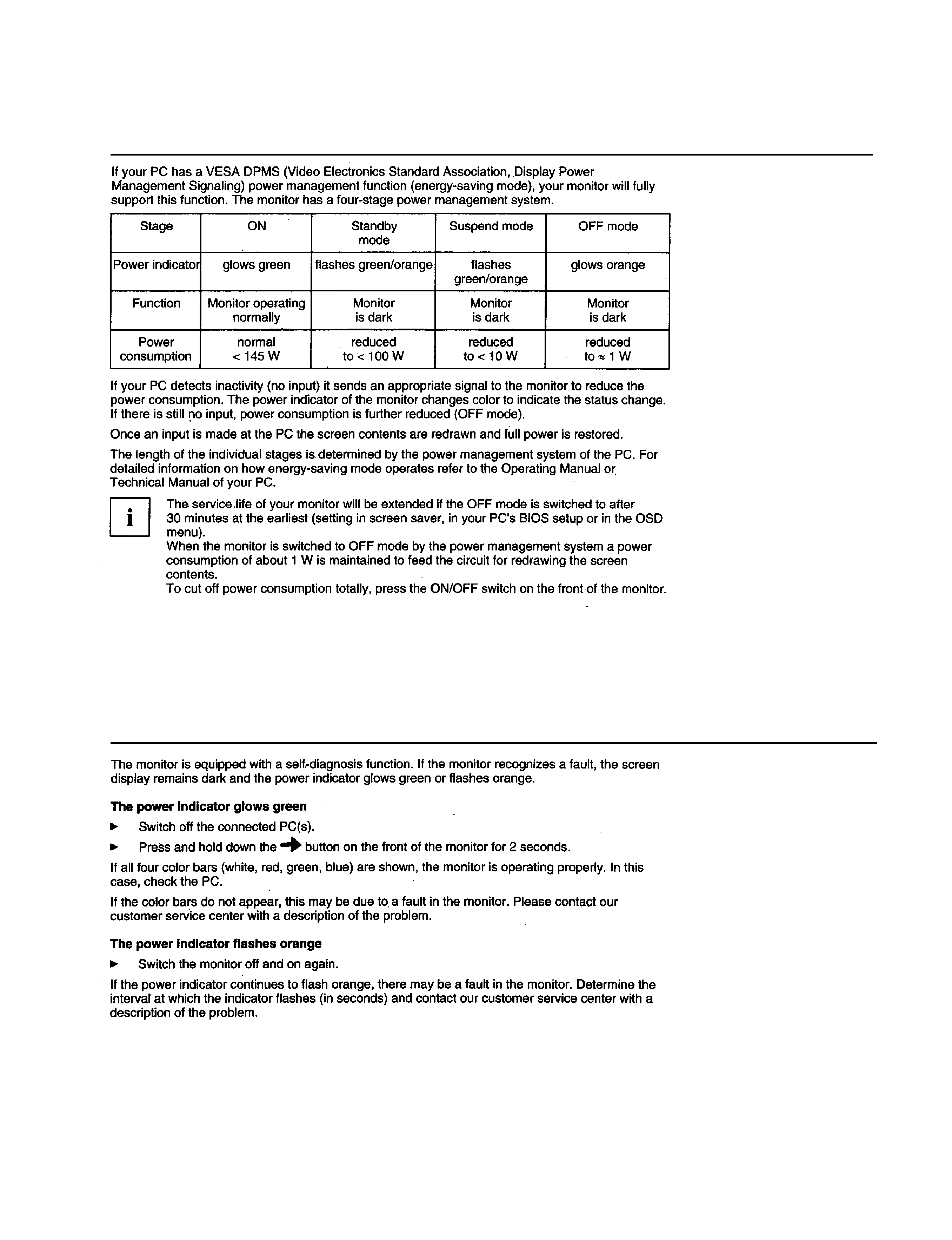
POWER SAVING FUNCTION
DIAGNOSIS
MCM-21T2
4
MODE AT PRODUCTION
MODE 8
MODE 9
MODE 10
MODE 11
MODE 12
MODE 13
MODE 14
RESOLUTION
1152 X 864
1280 X 1024
1280 X 1024
1600 X 1200
1600 X 1200
1856 X 1392
1920 X 1440
CLOCK
172.000 MHz
157.500 MHz
184.900 MHz
229.500 MHz
270.0 MHz
288.00 MHz
297.000 MHz
-- HORIZONTAL --
H-FREQ
109.694 kHz
91.146 kHz
107.002 kHz
106.250 kHz
118.838 kHz
112.50 kHz
112.500 kHz
usec
usec
usec
usec
usec
usec
usec
H. TOTAL
9.116
10.971
9.346
9.412
8.415
8.889
8.889
H. BLK
2.419
2.844
2.423
2.440
2.489
2.444
2.424
H. FP
0.186
0.406
0.173
0.279
0.237
0.444
0.485
H. SYNC
0.744
1.016
0.692
0.837
0.830
0.778
0.754
H. BP
1.488
1.422
1.558
1.325
1.422
1.222
1.185
H. ACTIV
6.698
8.127
6.923
6.972
5.926
6.444
6.465
-- VERTICAL --
V. FREQ (HZ)
120.015 Hz
85.024 Hz
99.91 Hz
85.000 Hz
94.692 Hz
75.00 Hz
75.000 Hz
lines
lines
lines
lines
lines
lines
lines
V. TOTAL
914
1072
1071
1250
1255
1500
1500
V. BLK
50
48
47
50
55
108
60
V. FP
21
2
1
2
1
1
V. SYNC
33
3
3
3
3
3
V. BP
45
44
42
46
50
104
56
V. ACTIV
864
1024
1024
1200
1200
1392
1440
-- SYNC --
INT(G)
NO
NO
NO
NO
NO
NO
NO
EXT (H/V) /POLARITY
YES N/N
YES P/P
YES P/P
YES P/P
YES N/P
YES N/P
YES N/P
EXT (CS) /POLARITY
NO
NO
NO
NO
NO
NO
NO
INT/NON INT
NON INT
NON INT
NON INT
NON INT
NON INT
NON INT
NON INT
2000.2.8 VER.
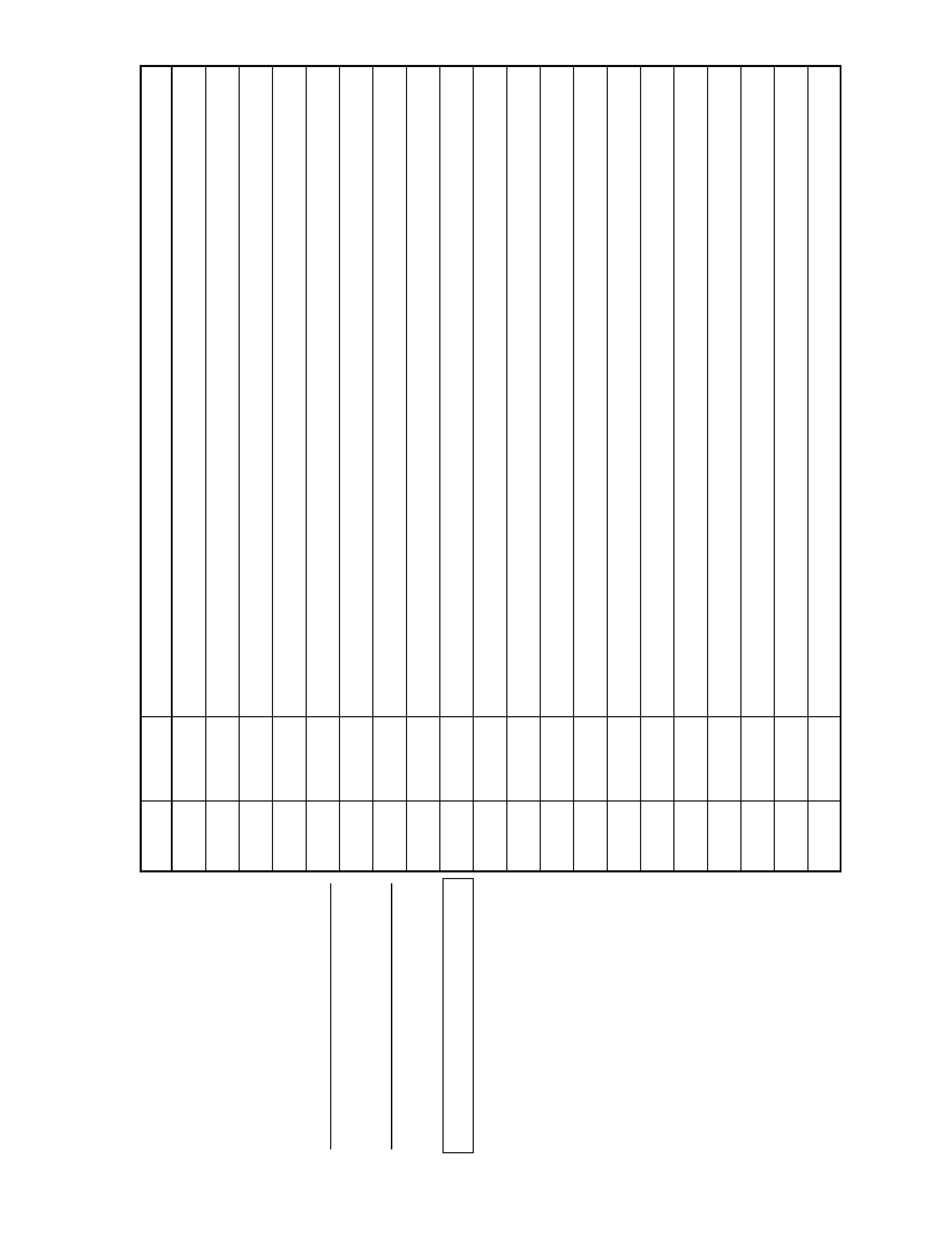
TIMING SPECIFICATION
MODE AT PRODUCTION
MODE 1
MODE 2
MODE 3
MODE 4
MODE 5
MODE 6
MODE 7
RESOLUTION
720 X 400
640 X 480
800 X 600
800 X 600
1024 X 768
1024 X 768
1152 X 864
CLOCK
28.325 MHz
25.175 MHz
56.250 MHz
67.500 MHz
94.500 MHz
111.2 MHz
108.000 MHz
-- HORIZONTAL --
H-FREQ
31.472 kHz
31.469 kHz
53.674 kHz
63.920 kHz
68.677 kHz
80.814 kHz
67.500 kHz
usec
usec
usec
usec
usec
usec
usec
H. TOTAL
31.774
31.778
18.631
15.644
14.561
12.374
14.815
H. BLK
6.355
6.356
4.409
3.793
3.725
3.165
4.148
H. FP
0.635
0.636
0.569
0.474
0.508
0.288
0.593
H. SYNC
3.813
3.813
1.138
0.948
1.016
1.151
1.185
H. BP
1.906
1.907
2.702
2.370
2.201
1.727
2.370
H. ACTIV
31.774
25.422
14.222
11.852
10.836
9.209
10.667
-- VERTICAL --
V. FREQ (HZ)
70.094 Hz
59.940 Hz
85.061 Hz
100.032 Hz
84.997 Hz
99.894 Hz
75.0 Hz
lines
lines
lines
lines
lines
lines
lines
V. TOTAL
449
525
631
639
808
809
900
V. BLK
49
45
31
39
40
41
36
V. FP
13
10
1
1
1
2
1
V. SYNC
22
33
3
3
3
V. BP
34
33
27
35
36
36
32
V. ACTIV
400
480
600
600
768
768
864
-- SYNC --
INT(G)
NO
NO
NO
NO
NO
NO
NO
EXT (H/V) /POLARITY
YES N/P
YES N/N
YES P/P
YES P/P
YES P/P
YES N/N
YES P/P
EXT (CS) /POLARITY
NO
NO
NO
NO
NO
NO
NO
INT/NON INT
NON INT
NON INT
NON INT
NON INT
NON INT
NON INT
NON INT