-- 1 --
MICROFILM
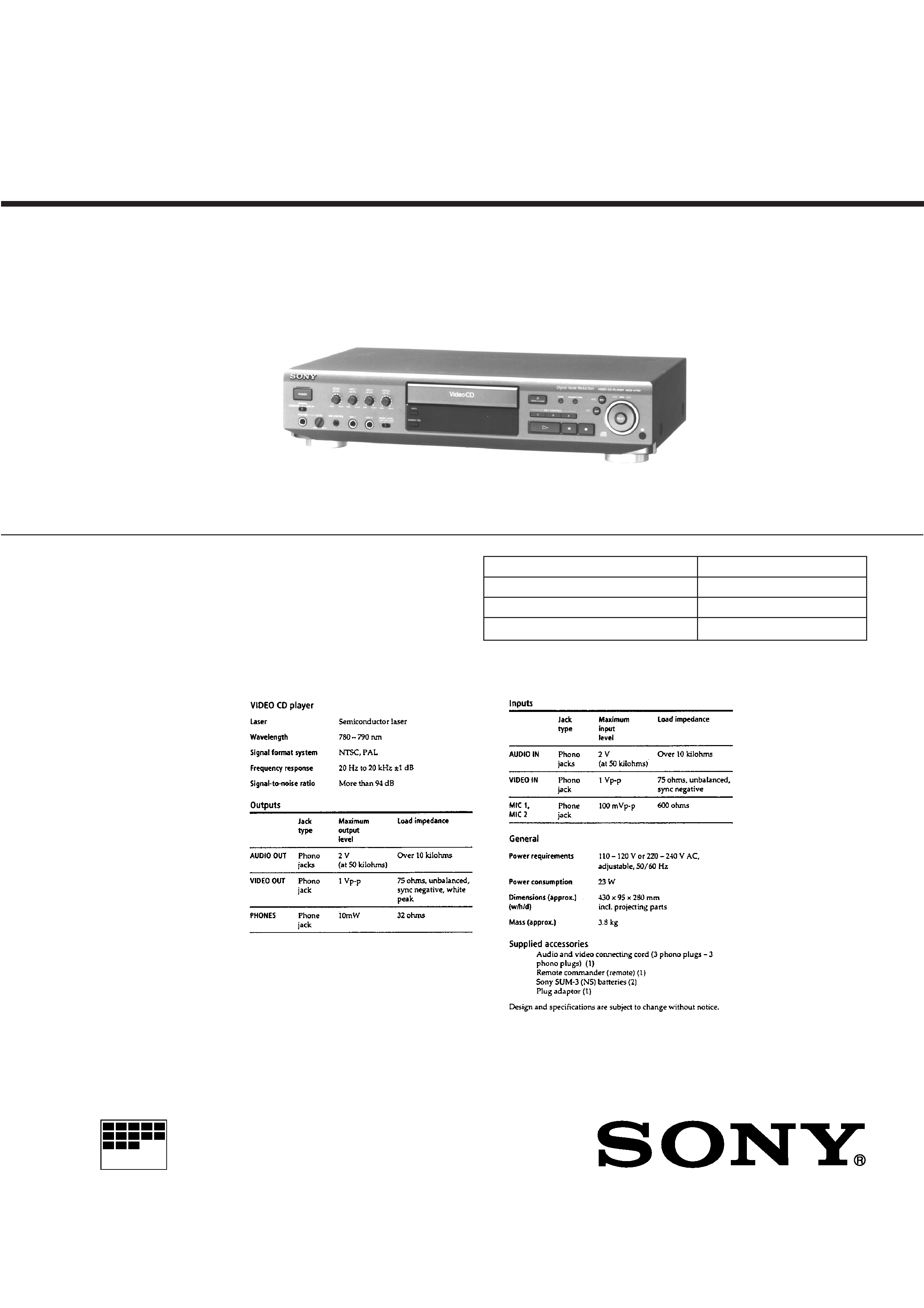
MCE-K700
E Model
SPECIFICATIONS
Model Name Using Similar Mechanism
MCE-F500
CD Mechanism Type
CDM14-5BD21
Base Unit Type
BU-5BD21
Optical Pick-up Type
KSS-213B
SERVICE MANUAL
VIDEO CD PLAYER
-- 2 --
Notes on chip component replacement
· Never reuse a disconnected chip component.
· Notice that the minus side of a tantalum capacitor may be
damaged by heat.
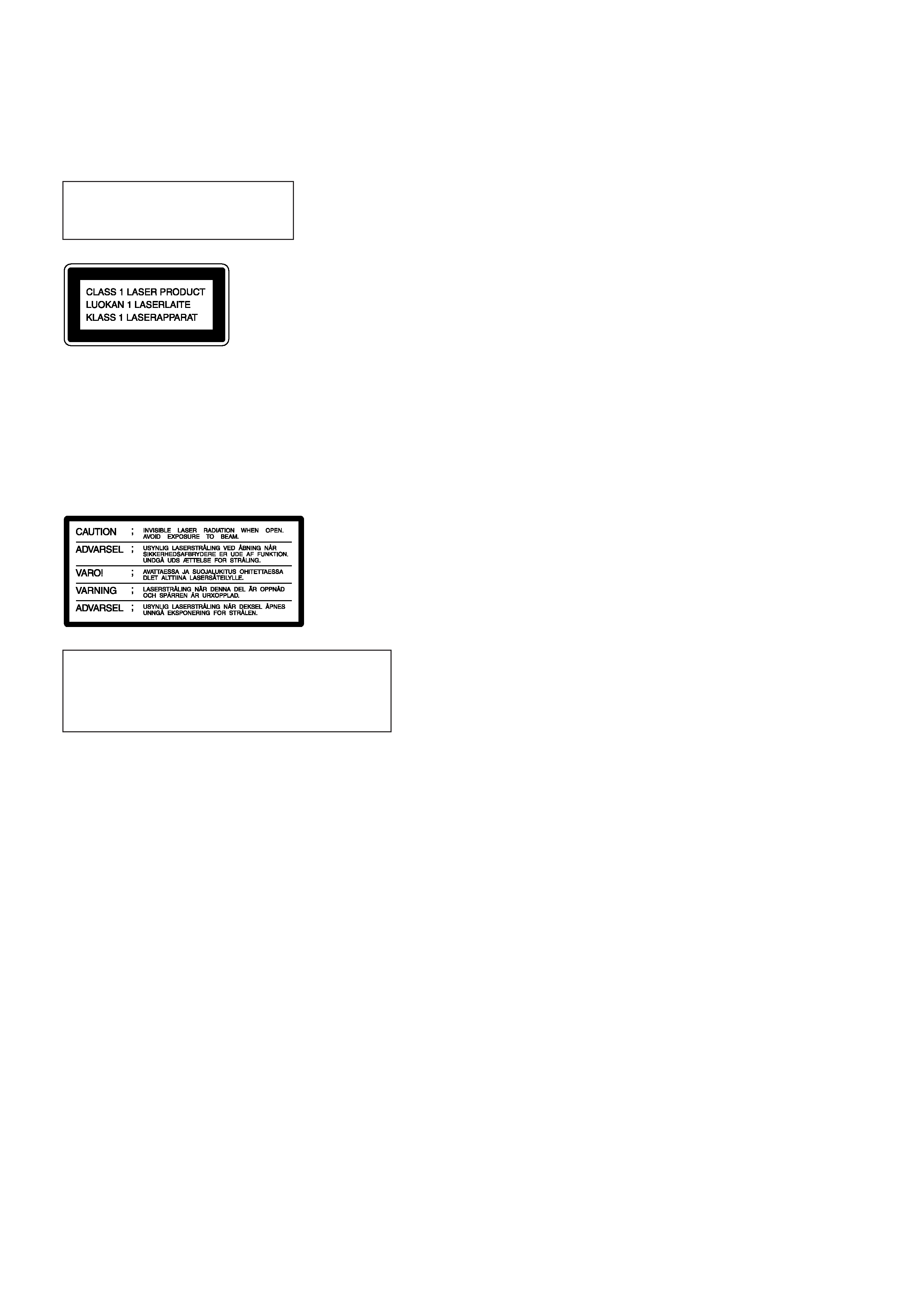
This appliance is classified as
a CLASS 1 LASER product.
The CLASS 1 LASER
PRODUCT MARKING is
located on the rear exterior.
This caution label is located inside
the unit.
The laser component in this product is ca-
pable of emitting radiation exceeding the
limit for Class 1.
SAFETY-RELATED COMPONENT WARNING !!
COMPONENTS IDENTIFIED BY MARK
! OR DOTTED LINE
WITH MARK
! ON THE SCHEMATIC DIAGRAMS AND IN
THE PARTS LIST ARE CRITICAL TO SAFE OPERATION.
REPLACE THESE COMPONENTS WITH SONY PARTS
WHOSE PART NUMBERS APPEAR AS SHOWN IN THIS
MANUAL OR IN SUPPLEMENTS PUBLISHED BY SONY.
CAUTION
Use of controls or adjustments or performance of
procedures other than those specified herein may result in
hazardous radiation exposure.
TABLE OF CONTENTS
1. SERVICING NOTE ....................................................... 3
2. TEST MODE ................................................................. 4
3. GENERAL
................................................................. 6
4. DISASSEMBLY
4-1.
Front Panel ......................................................................... 17
4-2.
Base Unit (BU-5BD21) ...................................................... 17
5. ELECTRICAL ADJUSTMENTS .............................. 18
6. DIAGRAMS
6-1.
Circuit Boards Location ..................................................... 20
6-2.
Block Diagrams
· CD, Main Section ............................................................ 21
· Video Section .................................................................. 25
6-3.
Printed Wiring Board -- BD Section -- ............................ 29
6-4.
Schematic Diagram -- BD Section -- ............................... 31
6-5.
Printed Wiring Board -- Main, Displ Section -- .............. 34
6-6.
Schematic Diagram -- Main, Disp Section -- .................. 37
6-7.
Schematic Diagram -- Video Section -- ........................... 43
6-8.
Printed Wiring Board -- Video Section -- ........................ 47
6-9.
IC Block Diagrams
· BD Section ...................................................................... 50
· Main, Disp Section .......................................................... 51
· Video Section .................................................................. 52
6-10. IC Pin Functions
· IC101 Digital Signal Processor (CXD2545Q)/
BD board ......................................................................... 55
· IC104 Digital Signal Processor for Karaoke
(CXD2721Q)/Main board ............................................... 58
· IC402 System Control, FL Driver (CXP82532-010Q)/
Disp board ....................................................................... 60
· IC501 Mechanism Control (HD6433032SK07F)/
Video board ..................................................................... 61
· IC507 MPEG Decoder (CXD1852Q)/Video board ........ 63
· IC509 Video Picture Quality Improvement (CXD1853Q)/
Video board ..................................................................... 67
· IC511 Digital Video Encoder (CXD1913Q)/
Video board ..................................................................... 70
· IC801 Character Generator (LC74760)/Video board ...... 73
7. EXPLODED VIEWS
7-1.
Case Section ....................................................................... 74
7-2.
Chassis Section ................................................................... 75
7-3.
Mechanism Deck Section (CDM14-5BD21) ..................... 76
7-5.
Base Unit Section (BU-5BD21) ......................................... 77
8. ELECTRICAL PARTS LIST ..................................... 78
-- 3 --
SECTION 1
SERVICING NOTE
SELF-DIAGNOSIS
This model has the self-diagnosis function for the video and audio
decoder sections.
Immediately after the power on, the self-diagnosis function searches
each operation of IC's around the mechanism control microcomputer
(IC501).
The LED (D501) on the VIDEO board indicates their results.
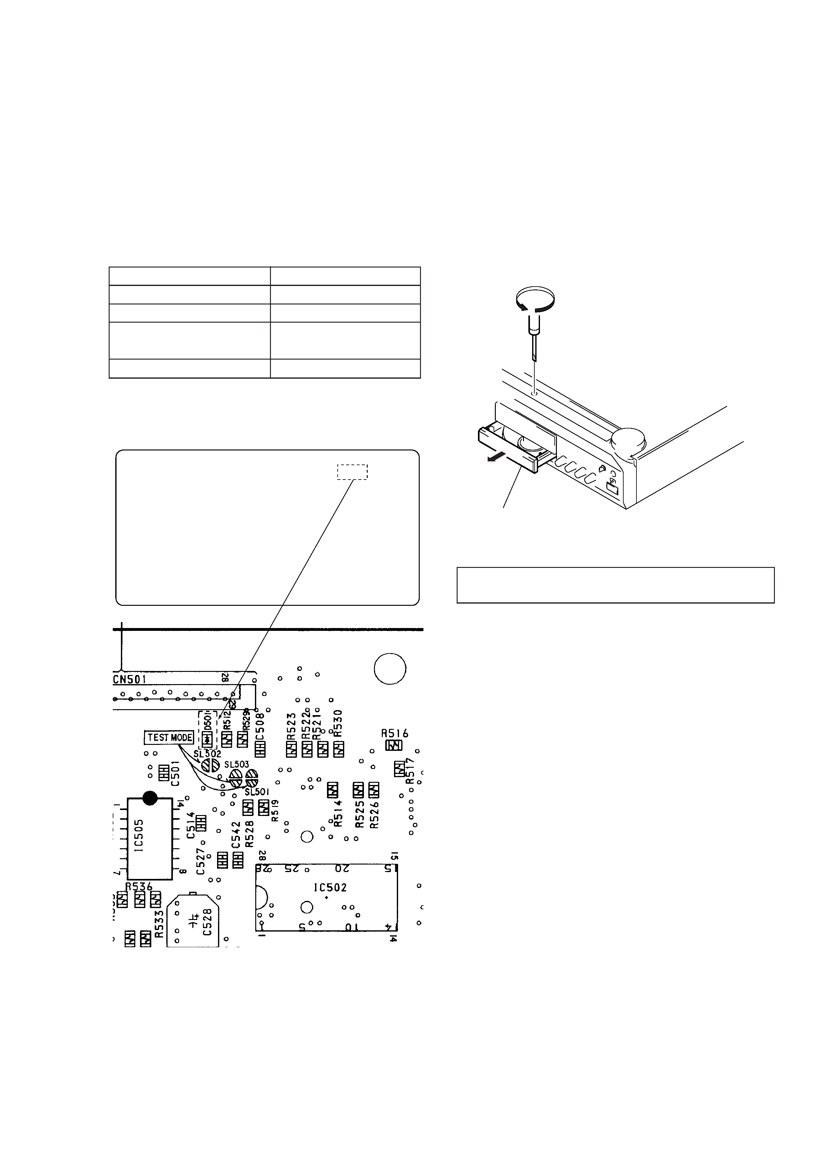
[VIDEO BOARD] -- SIDE B --
Insert a tapeing driver into the aperture of the unit bottom, and turn in
the direction of arrow (to OUT direction).
* To close the disc table, turn the driver in the reverse direction (to IN
direction).
NOTES ON HANDLING THE OPTICAL PICK-UP BLOCK
OR BASE UNIT
The laser diode in the optical pick-up block may suffer electrostatic
break-down because of the potential difference generated by the
charged electrostatic load, etc. on clothing and the human body.
During repair, pay attention to electrostatic break-down and also use
the procedure in the printed matter which is included in the repain
parts.
The flexible board is easily damaged and should be handled with
care.
NOTES ON LASER DIODE EMISSION CHECK
The laser beam on this model is concentrated so as to be focused on
the disc reflective surface by the objective lens in the optical pick-up
block. Therefore, when checking the laser diode emission, observe
from more than 30 cm away from the objective lens.
LASER DIODE AND FOCUS SEARCH OPERATION CHECK
Carry out the "S curve check" in "CD section adjustment" and check
that the S curve waveform is output four times.
HOW TO OPEN THE DISC TRAY WHEN POWER SWITCH
TURNS OFF
LED (D501) INDICATION
Light
1 time blinking (Repeatedly)
2 time blinking (Repeatedly)
3 time blinking (Repeatedly)
SYMPTOM
No error
External RAM error (IC502)
Video decoder error
(IC507)
Video RAM error (IC508)
Pull out disc table
-- 4 --
SECTION 2
TEST MODE
VIDEO CD COLOR-BARS MODE
On this mode, the data of the color-bars signal as a picture signal and
the 1kHz sine wave signal as a sound signal are output by the mecha-
nism control microcomputer (IC501) for video CD signal check. When
measurement of the voltage and waveform on the VIDEO board,
perform it in this mode.
For refernce, the color-bars signal can be observed at J101 (VIDEO
OUT) and the sound signal can be observed at J102 (AUDIO OUT)
using an oscilloscope.
1. Turn the power on.
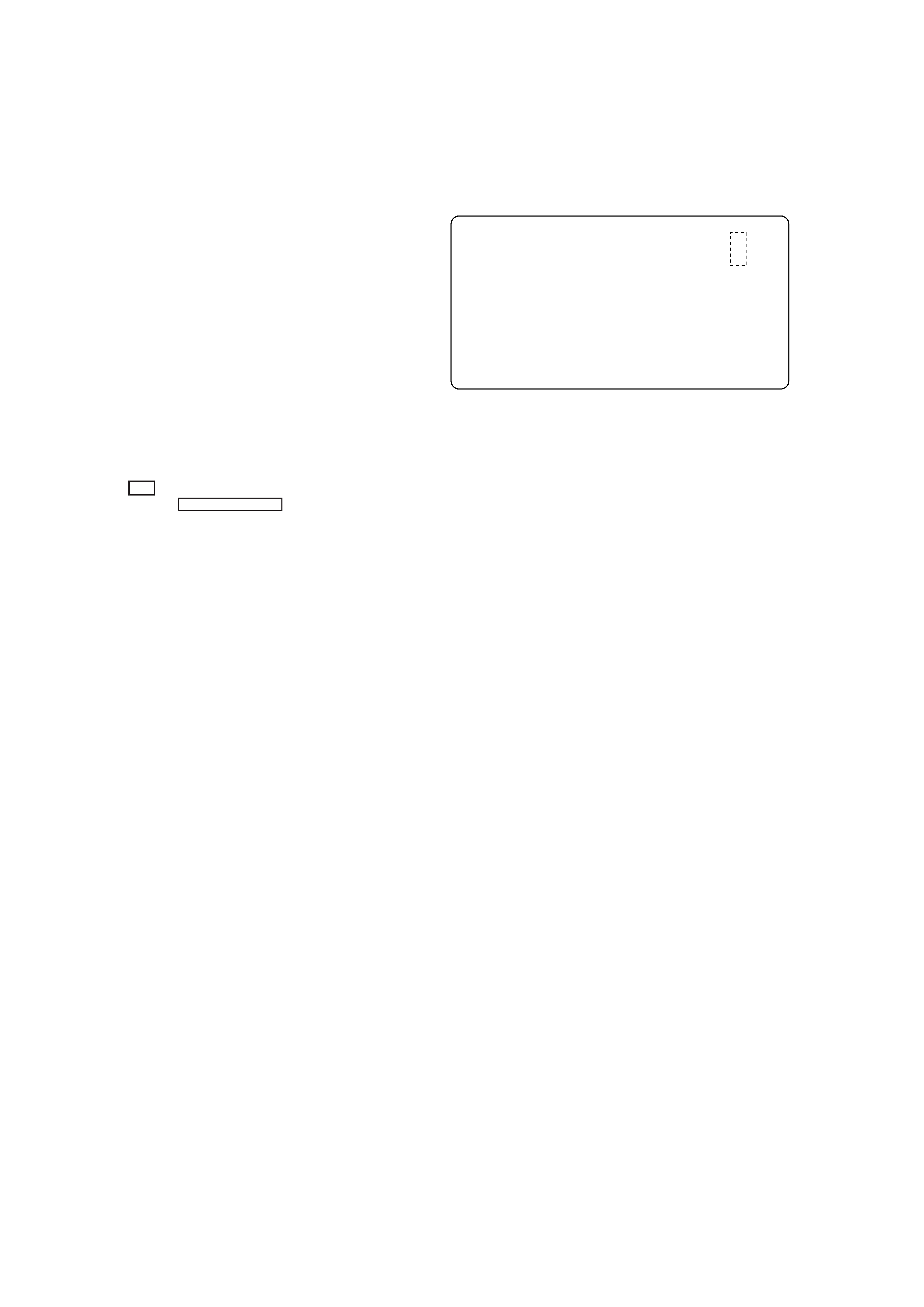
2. Connect the SL501 (C BAR) on the VIDEO board with solder.
3. After measuring, remove the soldering installed.
E-F BALANCE MODE
· Refer to SECTION 5 ELECTRICAL ADJUSTMENTS page 15.
1. Turn the power on.
2. Connect the SL502 and SL503 on the VIDEO board with solder.
3. Press the
· button in playback.
4. Every pressing the KARAOKE STAR button, the tracking servo
and the sledding servo are turned on or off.
5. When the servo is OFF, the counter on front panel will not be
changed.
6. After measuring, remove the soldering installed.
[VIDEO BOARD] -- SIDE B --
-- 5 --
Lighting of All Fluorescent Indicator Tube Displays
and Key Check Mode
1. Connect the TEST2 (Short round) on the Main board with solder.
2. Connect the power plug to the outlet.
3. All the Fluorescent Indicator tube displays light up.
4. Press any button to enter the key check mode. In the key check
mode, each time a button is pressed, figures displayed on the Fluo-
rescent Indicator tube displays increase. However, figures will not
increase for buttons which have been pressed once.
The button number corresponding to the button pressed will also
be displayed. Button numbers are displayed only while the corre-
sponding buttons are pressed.
5. To exit the test mode, disconnect the power plug from the outlet.
7-segment display
[PANEL BOARD] (Conductor side)
Button Name
Button Number (Displayed only while a
button is pressed.)
KEY CONTROL
~
KEY CONTROL
N
KEY CONTROL
n
KARAOKE STAR
DNR
§ OPEN/CLOSE
0
) ±
SELECT
POWER
P
·
Figure 9
Figure 10
Figure 11
Figure 12
Figure 13
Figure 14
Figure 21
Figure 22
Figure 23
Figure 38 and adjustment LED (D403)
All Fluorescent Indicator tube
displays light up
Surround and other displays light up alter-
nately.
8 8 8 8
8 8 8 8
~
IC402
TEST 2
R445
R424
n
Count up display
88888888
Button number display
7 segments displays light up alternately
KEY CONTROL
RESUME
SUR
KARAOKE
THEATER
PON
KEY CONTROL
AUTO
MUSIC
STAR
n