MCE-C98K
E Model
SERVICE MANUAL
VIDEO CD PLAYER
MICROFILM
Model Name Using Similar Mechanism
MCE-C50K
CD Mechanism Type
CDM27-5BD24
Base Unit Name
BU-5BD24
Optical Pick-up Name
KSS-213B/S-N
SPECIFICATIONS
-- 2 --
TABLE OF CONTENTS
SAFETY-RELATED COMPONENT WARNING!!
COMPONENTS IDENTIFIED BY MARK ! OR DOTTED LINE WITH
MARK ! ON THE SCHEMATIC DIAGRAMS AND IN THE PARTS
LIST ARE CRITICAL TO SAFE OPERATION. REPLACE THESE
COMPONENTS WITH SONY PARTS WHOSE PART NUMBERS
APPEAR AS SHOWN IN THIS MANUAL OR IN SUPPLEMENTS
PUBLISHED BY SONY.
1. SERVICING NOTES ······················································ 3
2. TEST MODE ······································································ 5
3. GENERAL ·········································································· 7
4. DISASSEMBLY
4-1.
Case, Bottom Plate, Front Panel ········································ 9
4-2.
Back Panel and Disc Table ················································ 9
4-3.
Optical Pick-up Block Assembly ····································· 10
4-4.
Bracket (Gear) Assembly ················································· 10
5. ELECTRICAL ADJUSTMENTS
CD Section ··········································································· 11
Video Section ······································································· 12
6. DIAGRAMS
6-1.
Block Diagrams
· Servo Section ································································ 13
· Audio/Video Section ····················································· 15
· Display/Key Control/ Power Supply Section ··············· 17
6-2.
Circuit Boards Location ··················································· 19
6-3.
Printed Wiring Board Video Section ························· 23
6-4.
Schematic Diagram Video Section (1/2) ·················· 25
6-5.
Schematic Diagram Video Section (2/2) ·················· 27
6-6.
Schematic Diagram Sensor Section ··························· 29
6-7.
Printed Wiring Board Sensor Section ························ 30
6-8.
Schematic Diagram BD Section ································ 31
6-9.
Printed Wiring Board BD Section ····························· 33
6-10. Schematic Diagram Main Section ····························· 35
6-11. Printed Wiring Board Main Section ·························· 37
6-12. Schematic Diagram Display Section ························· 39
6-13. Printed Wiring Board Display Section ······················ 41
6-14. Schematic Diagram SW Section ································ 43
6-15. Printed Wiring Board SW Section ······························ 45
6-16. IC Block Diagrams ·························································· 47
6-17. IC Pin Function Descriptions ··········································· 50
7. EXPLODED VIEWS
7-1.
Front Panel, Cover Section ·············································· 56
7-2.
Back Panel, Disk Table Section ······································· 57
7-3.
Chassis Section ································································ 58
7-4.
Base Unit Section (BU-5BD24) ······································ 59
8. ELECTRICAL PARTS LIST ····································· 60
Notes on chip component replacement
· Never reuse a disconnected chip component.
· Notice that the minus side of a tantalum capacitor may be dam-
aged by heat.
This appliance is classified as a CLASS 1 LASER product. The
CLASS 1 LASER PRODUCT MARKING is located on the rear
exterior.
The following caution label is located inside the unit.
Laser component in this product is capable
of emitting radiation exceeding the limit for
Class 1.
CAUTION
Use of controls or adjustments or performance of procedures
other than those specified herein may result in hazardous radiation
exposure.
-- 3 --
SECTION 1
SERVICING NOTES
The laser diode in the optical pick-up block may suffer electrostatic
break-down because of the potential difference generated by the
charged electrostatic load, etc. on clothing and the human body.
During repair, pay attention to electrostatic break-down and also
use the procedure in the printed matter which is included in the
repair parts.
The flexible board is easily damaged and should be handled with
care.
NOTES ON LASER DIODE EMISSION CHECK
The laser beam on this model is concentrated so as to be focused on
the disc reflective surface by the objective lens in the optical pick-
up block. Therefore, when checking the laser diode emission,
observe from more than 30 cm away from the objective lens.
LASER DIODE AND FOCUS SEARCH OPERATION
CHECK
Carry out the "S curve check" in "CD section adjustment" and check
that the S curve waveform is output repeatedly.
NOTES ON HANDLING THE OPTICAL PICK-UP
BLOCK OR BASE UNIT
HOW TO OPEN THE DISC TRAY WHEN POWER SWITCH
TURNS OFF
Insert a tapeing driver into the aperture of the unit bottom, and turn
in the direction of arrow (to OUT direction).
* To close the disc table, turn the driver in the reverse direction (to
IN direction).
SELF-DIAGNOSIS
This unit is equipped with a self-diagnosis function.
The function is used for diagnosing the conditions of the circuits of
the VIDEO board.
The circuits can be determined if normal or abnormal by the lighting
of D502 on the VIDEO board.
Lighting of D502
When lit
: Operates normally
Blinks repeatedly : The circuit may be faulty.
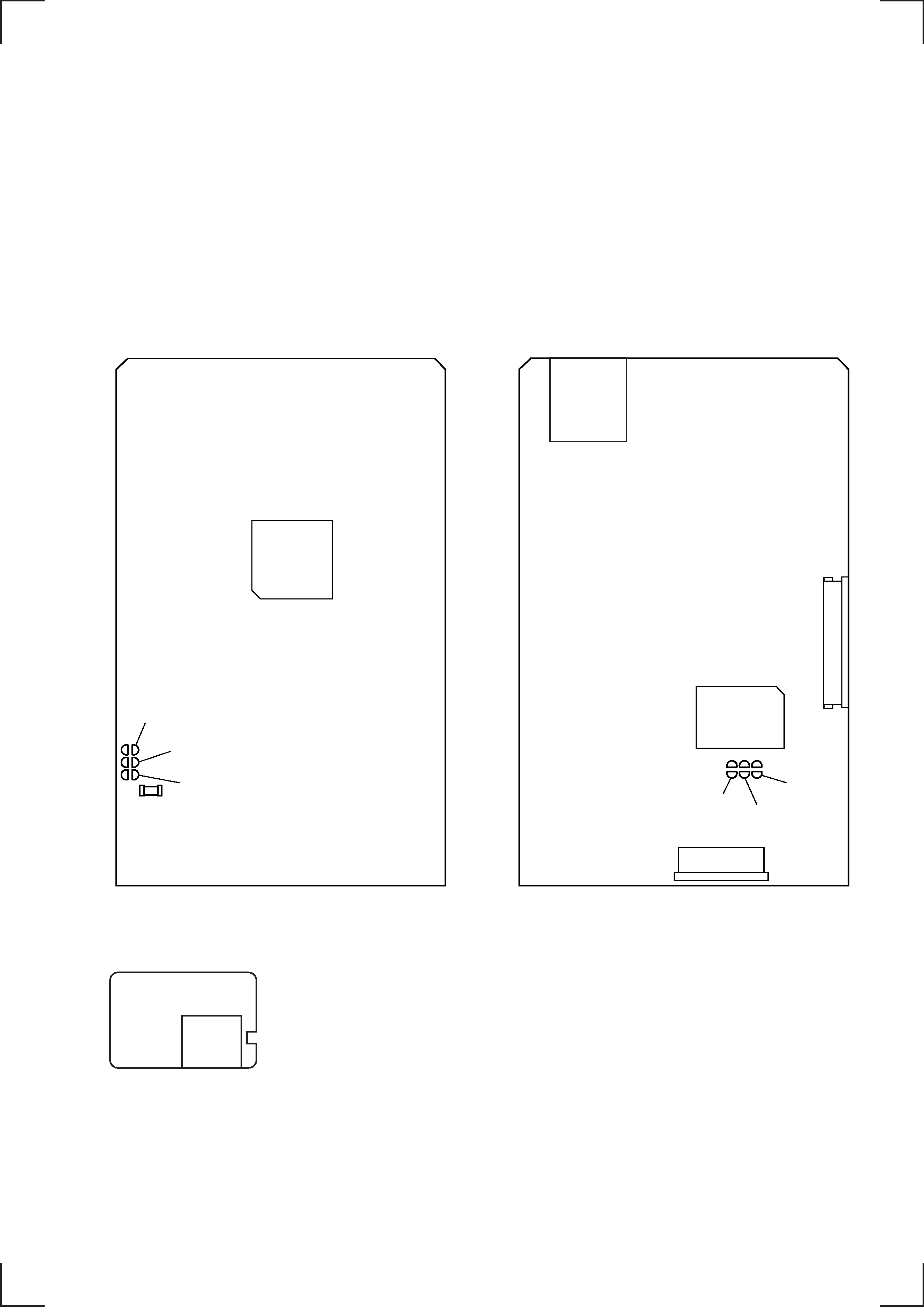
[VIDEO Board] (Side A)
IN
OUT
minus driver
Pull out disc table.
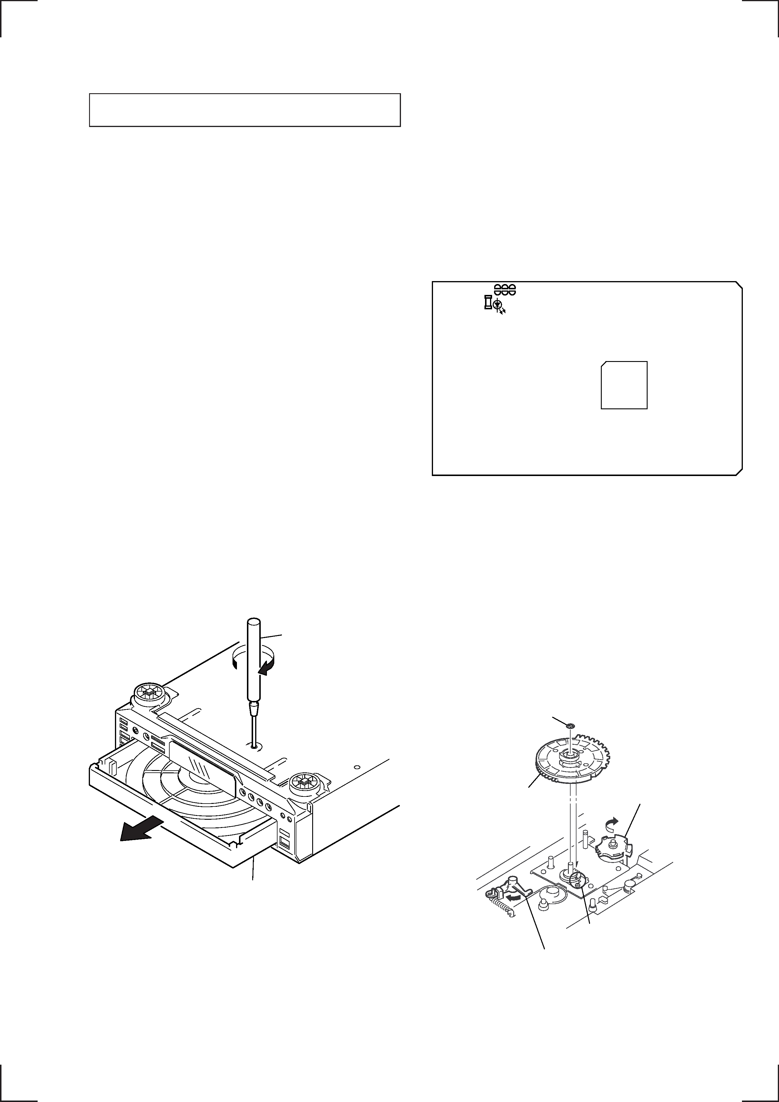
NOTE FOR MAIN GEAR INSTALLATION
A
B
1 Set the mark of ROTARY
ENCODER.
2 Slide the SET LEVER
to the arrow
B direction.
3 Rotate the GEAR
(U/D) in the direction
of arrow
A.
(To DOWN position)
5 Stopper washer (5)
4 Install the MAIN GEAR
as show in the drawing.
D502
IC505
The following extension cable is required to check and adjust the
VIDEO board.
J-2501-155-A
CN601/MAIN
CN451/VIDEO
J-2501-156-A
CN906/MAIN
CN453/VIDEO
J-2501-157-A
CN101/BD
CN501/VIDEO
-- 4 --
HOW TO CLEAN THE OPTICAL PICK-UP LENS
2 Remove the MAGNET ASSY
with tweezers.
3 Move the optical pick-up block by
rotating the gear, to the position
where lens can be cleaned.
Then clean the lens.
1 OPEN THE DISC TRAY
Refer to " HOW TO OPEN THE
DISC TRAY WHEN POWER
SWITCH TURNS OFF " Page 3.
OPTICAL PICK-UP LENS
-- 5 --
SECTION 2
TEST MODE
[VIDEO CD Color-bars Mode]
On this mode, the data of the color-bars signal as a picture signal and the 1 kHz sine wave signal as a sound signal are output by the
mechanism controller (IC502) for the video CD signal check. When measurement of the voltage and waveform on the VIDEO board,
perform it in this mode.
For reference, the color-bars signal can be observed at J302 (VIDEO OUT) and the sound signal can be observed at J151 (AUDIO
OUT) using an oscilloscope.
Procedure:
1. Connect the lead wire to both ends of the land of SL503 on the VIDEO board.
2. Turn the power on.
3. After 2 or 3 seconds later, connect the lead wire.
4. After measuring, remove the lead wire connected.
[VIDEO Board] (Side A)
[VIDEO Board] (Side B)
D502
SL501
SL503
SL502
IC505
SL503
IC502
J302
CN503
CN501
SL502
SL501
J151
[AUDIO Board]