1
MICROFILM
Model Name Using Similar Mechanism
NEW
Tape Transport Mechanism Type
MZ-98-100
SERVICE MANUAL
US Model
Canadian Model
AEP Model
E Model
Tourist Model
M-98V
MICROCASSETTETM-CORDER
Tape
y (normal position type)
Recording system
2-track 1 channel monaural
Frequency range
400 - 3,000 Hz (2.4 cm/s)
Speaker
Approx. 2.8 cm (1 1/8 in.) dia.
Power output
250 mW
Input
Microphone input jack (minijack/plug in power) sensitivity
0.37 mV for 3 kilohms or lower impedance microphone
Output
Earphone jack (minijack) for 8 - 300 ohms earphone
Power requirements
3 V DC batteries R03 (size AAA)
× 2/External DC 3 V power
sources
Battery life (Approximate hours)
(EIAJ*)
Battery
Recording
Sony alkaline LR03 (SG)
9.5
Sony R03 (SB)
3.5
* Measured value by the standard of EIAJ (Electronic Industries
Association of Japan). (Using a Sony Microcassette tape)
For maximum performance, we recommend that you use
SPECIFICATIONS
Ver 1.0 1999. 03
alkaline batteries.
Dimensions (w/h/d) (incl. projecting parts and controls)
Approx. 60.5
× 93.9 × 26.0 mm (2 1/2 × 3 3/4 × 1 11/16 in.)
Mass
Approx. 130 g (4.6 oz.)
Supplied accessories
Remote control microphone ECM-J805 (1)
Microcassette tape MC-30 (1)
Earphone MDR-E123 (1)
Carrying case (1)
Hand strap (1)
Batteries R03 (SB) (2) (Tourist model only)
Design and specifications are subject to change without notice.

2
TABLE OF CONTENTS
1. SERVICE NOTE .......................................................... 3
2. GENERAL .................................................................... 4
3. DISASSEMBLY
3-1. Panel (Rear) Assy ................................................................ 5
3-2. Panel (Lid) Assy .................................................................. 5
3-3. MD Block Assy ................................................................... 6
3-4. Main board, complete ......................................................... 6
3-5. Frame .................................................................................. 7
3-6. Mode Motor Block .............................................................. 7
4. MECHANICAL ADJUSTMENTS .............................. 8
5. ELECTRICAL ADJUSTMENTS ............................... 8
6. DIAGRAMS
6-1. IC Pin Description ............................................................. 10
6-2. Block Diagram .................................................................. 12
6-3. Printed Wiring Board ........................................................ 14
6-4. Schematic Diagram ........................................................... 17
7. EXPLODED VIEWS
7-1. Panel (Lid) Section ............................................................ 22
7-2. Main Board Section .......................................................... 23
7-3. Mechanism Section (1) ..................................................... 24
7-4. Mechanism Section (2) ..................................................... 25
8. ELECTRICAL PARTS LIST .................................... 26
Notes on Chip Component Replacement
· Never reuse a disconnected chip component.
· Notice that the minus side of a tantalum capacitor may be dam-
aged by heat.
3
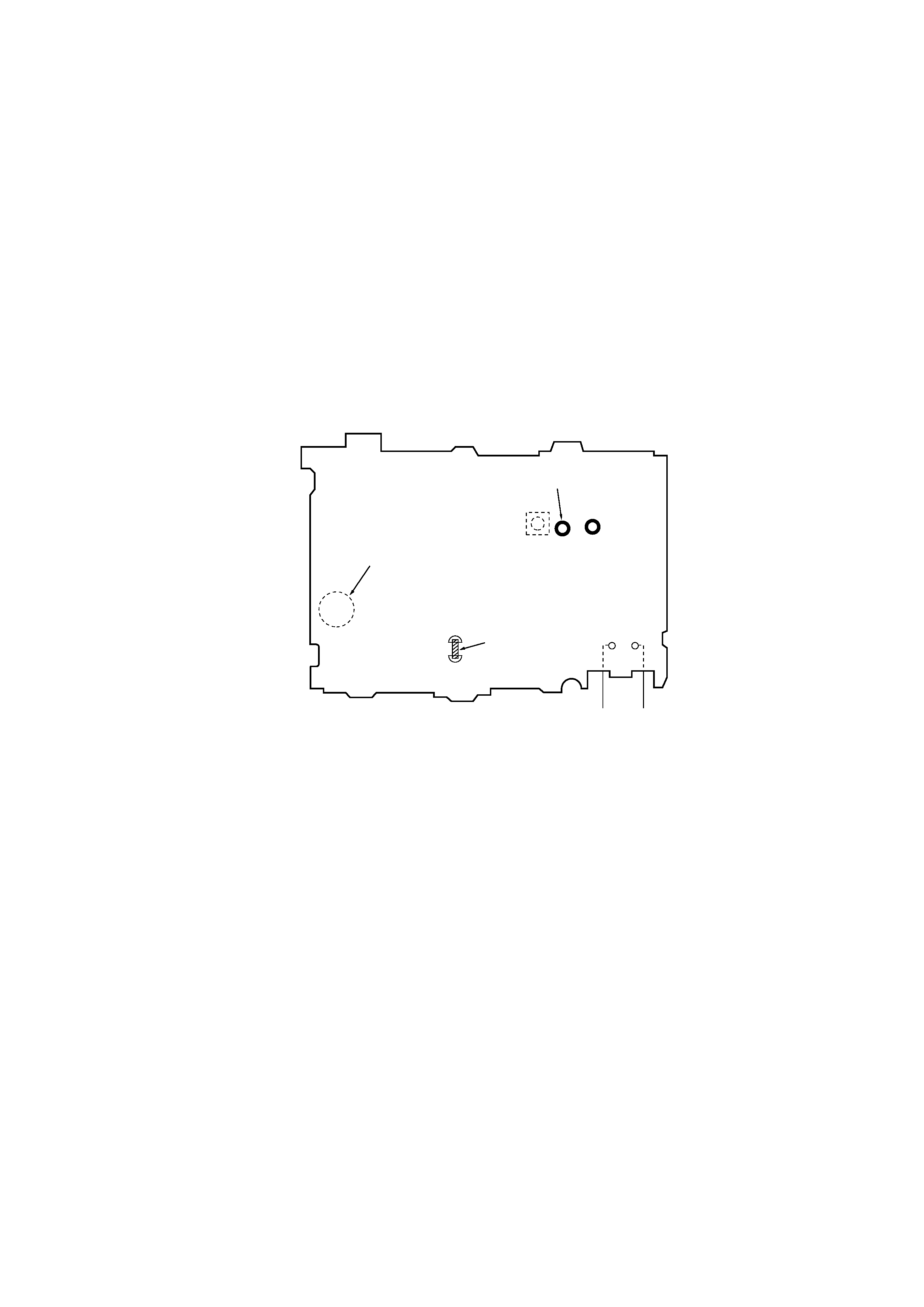
BP701
(SERVICE)
S701
(MODE SELECT)
TP38
S703
(TAPE DET)
TP66
SHORT
MAIN BOARD (SIDE B)
`
terminal ' terminal
SECTION 1
SERVICE NOTE
This set uses the photo reflector PH701 to detect the rotation of the gear. PH701 is on the main board and so removal of the main board does
not allow the set to detect the rotation of the gear. This makes motor control impossible which prevents normal operation.
When repairing the set as energized with the main board removed, proceed as follows:
· Service the Main Board
1. Short the BP701 (SERVICE) on the main board. (see the Fig. 1.)
2. Refer to the "SECTION3 DISASSEMBLY" (page 5) and open the main board.
3. Put a tape in the set.
4. Fixed at S703 (TAPE DET) on mode or connect the jumper wire between TP38 and GND (TP66).
5. Supply 3 V DC to the battery terminals.
6. Rotate the S701 (MODE SELECT) one turn by hand (mode sensor).
7. Press the desired operating switch (
9 (, FF, etc.).
8. Check the mode on the liquid crystal panel. Use item 6 repeatedly to switch modes.
9. When finished with the job, disconnect the power and open (remove the short) the BP701 (SERVICE).
Fig. 1.
4
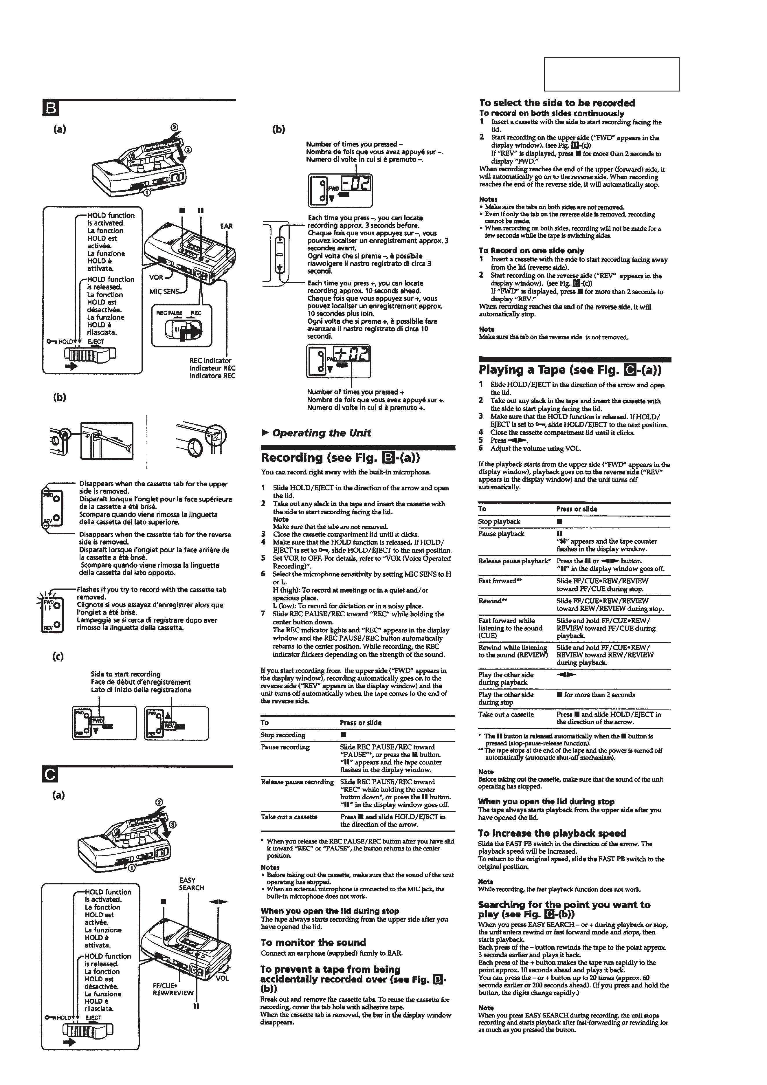
SECTION 2
GENERAL
This section is extracted
from instruction manual.
5
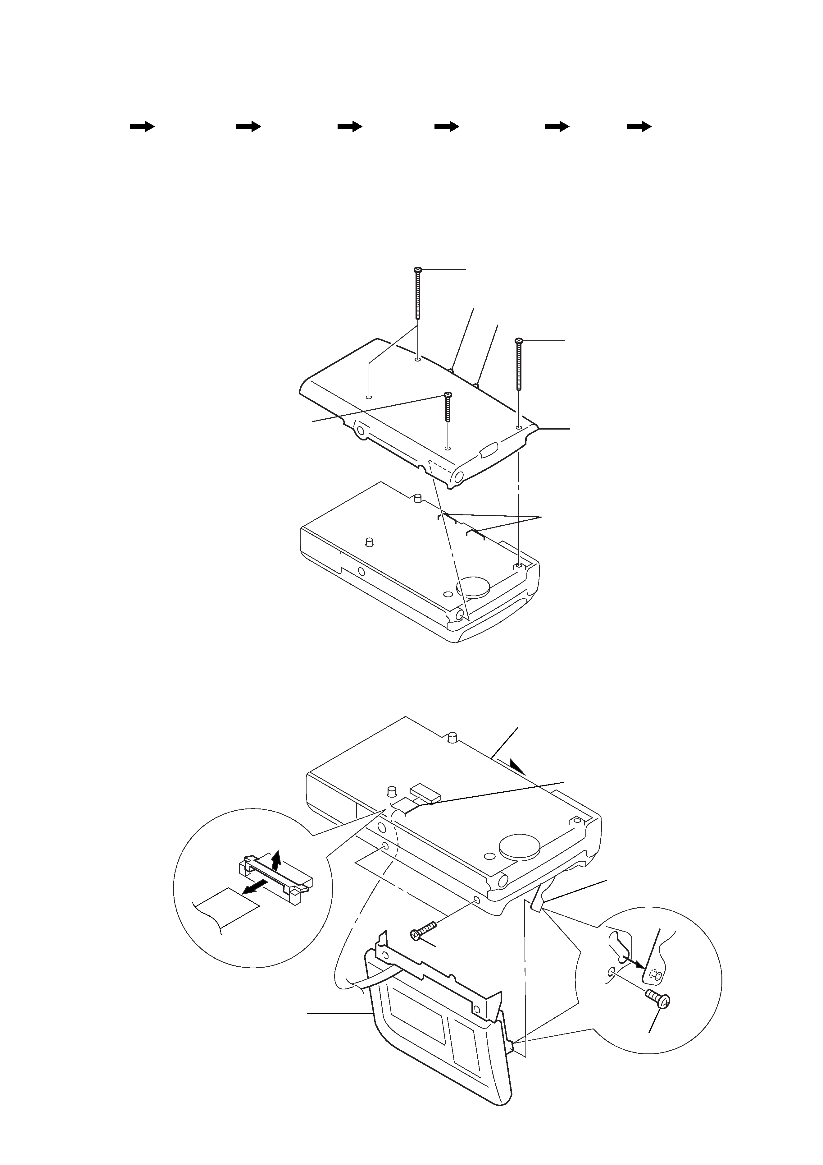
1 screws (B1.7x18) (G), tapping
2 screw (B1.7x18) (G), tapping
3 screw (M1.4x5.0), locking
4 panel (rear) assy
switches
knob (MIC SENS)
knob (V ·O ·R)
SECTION 3
DISASSEMBLY
Note : This set can be disassemble according to the following sequence.
Note : Follow the disassembly procedure in the numerical order given.
3-1. PANEL (REAR) ASSY
· When installing, position the knobs (V·O·R, MIC SENS) and the switches.
Set
Panel (rear)
assy
Panel (lid)
assy
MD block
assy
Main board,
complete
Frame
Mode motor
block
a
b
3 screws (M1.4),
toothed lock
2 CN102
1 knob (EJECT)
5 lever (C holder) assy
4 screw
6 panel (lid) assy
3-2. PANEL (LID) ASSY