M-740V
E Model
Chinese Model
East European Model
SERVICE MANUAL
MICROCASSETTETM-CORDER
Sony Corporation
Audio Entertainment Group
General Engineering Dept.
9-873-089-11
2001B1600-1
© 2001.2
SPECIFICATIONS
Ver 1.0 2001. 02
Model Name Using Similar Mechanism
M-730V
Tape Transport Mechanism Type
MZ-730V-99
Tape
(normal position type)
Recording system
2-track 1-channel monaural
Speaker
Approx. 3.6 cm (17/16 in.) dia.
Tape speed
2.4 cm/s (15/16 ips), 1.2 cm/s (15/32 ips)
Frequency range
300 - 4,000 Hz (with TAPE SPEED switch at 2.4 cm/s)
Input
Microphone input jack (minijack/PLUG IN POWER)
sensitivity 0.22 mV for 3 kilohms or lower impedance microphone
Output
Earphone jack (minijack) for 8 - 300 ohms earphone
Power output (at 10% harmonic distortion)
250 mW
Power requirements
3 V DC batteries R6 (size AA)
× 2/External DC 3V power sources
Dimensions (w/h/d)
Approx. 62.2
× 120.5 × 25.5 mm (21/2 × 43/4 × 11/16 in.) incl. projecting
parts and controls
Mass
Approx. 130 g (4.6 oz)
Supplied accessories
Microcassette tape MC-30 (1) (European model only)
Batteries R6P (SR) (2) (European model only)
Carrying pouch (1) (M-830V and European model of M-740V only)
Design and specifications are subject to change without notice.

2
M-740V
TABLE OF CONTENTS
Flexible Circuit Board Repairing
· Keep the temperature of the soldering iron around 270°C during
repairing.
· Do not touch the soldering iron on the same conductor of the
circuit board (within 3 times).
· Be careful not to apply force on the conductor when soldering
or unsoldering.
Notes on Chip Component Replacement
· Never reuse a disconnected chip component.
· Notice that the minus side of a tantalum capacitor may be dam-
aged by heat.
1. GENERAL .................................................................... 3
2. DISASSEMBLY
2-1. Lid Assy, Cassette .......................................................... 4
2-2. Lid, Battery Case ........................................................... 4
2-3. Cabinet (Rear) Assy ....................................................... 5
2-4. Speaker Assy, Microphone ............................................ 5
2-5. Main Board .................................................................... 6
2-6. Mechanism Deck ........................................................... 6
2-7. LED Unit ....................................................................... 7
2-8. Head, Creamic (HRPE901, 902) ................................... 7
3. MECHANICAL ADJUSTMENTS .............................. 8
4. ELECTRICAL ADJUSTMENTS ............................... 8
5. DIAGRAMS
5-1. Block Diagram ............................................................ 11
5-2. Printed Wiring Board ................................................... 12
5-3. Schematic Diagram ..................................................... 13
6. EXPLODED VIEWS
6-1. Cabinet Section ........................................................... 14
6-2. Mechanism Deck Section (1) ...................................... 15
6-3. Mechanism Deck Section (2) ...................................... 16
7. ELECTRICAL PARTS LIST ..................................... 17
3
M-740V
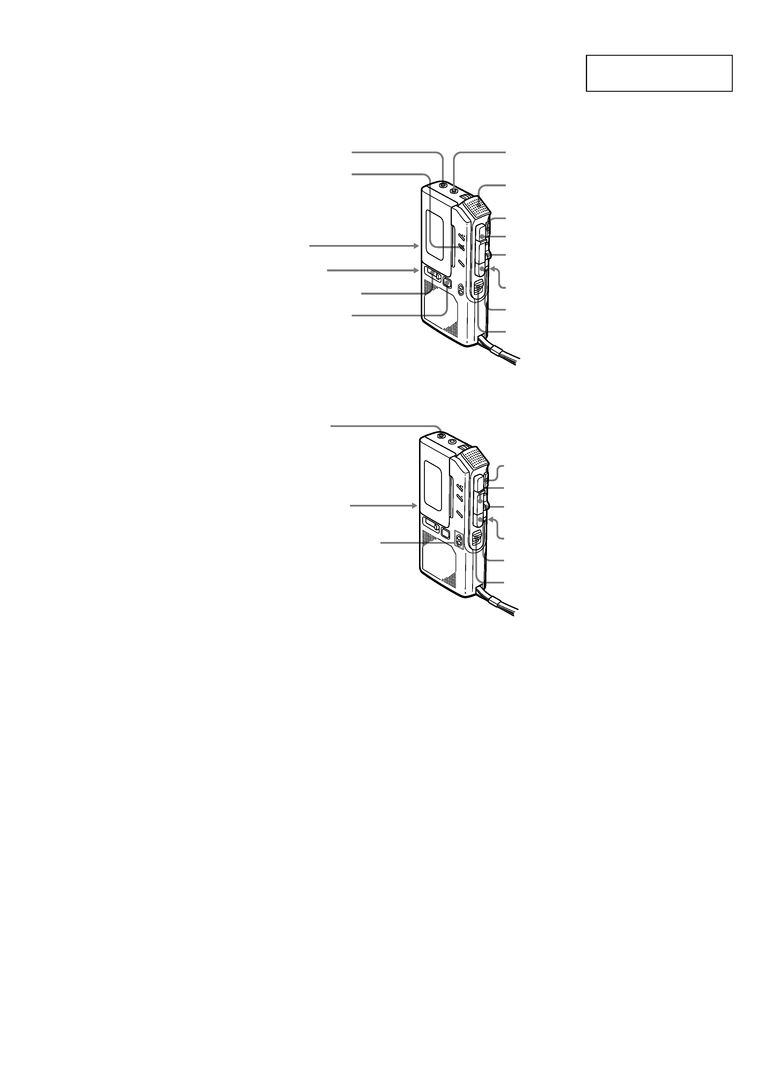
SECTION 1
GENERAL
EAR
Microphone
Micrófono
z
>
PAUSE
CUE/
REVIEW
xZ
VOR
TAPE SPEED
TAPE COUNTER
CUE MARKER
MIC (PLUG
IN POWER)
REC lamp (M-830V)
Indicador REC (M-830V)
REC/BATT lamp (M-740V)
Indicador REC/BATT (M-740V)
FAST PB
EAR
nN
>
PAUSE
CUE/
REVIEW
xZ
TAPE SPEED
FAST PB
Tape direction
indicators
Indicadores de
sentido de la cinta
DIR.
DIR.
This section is extracted
from instruction manual.
4
M-740V
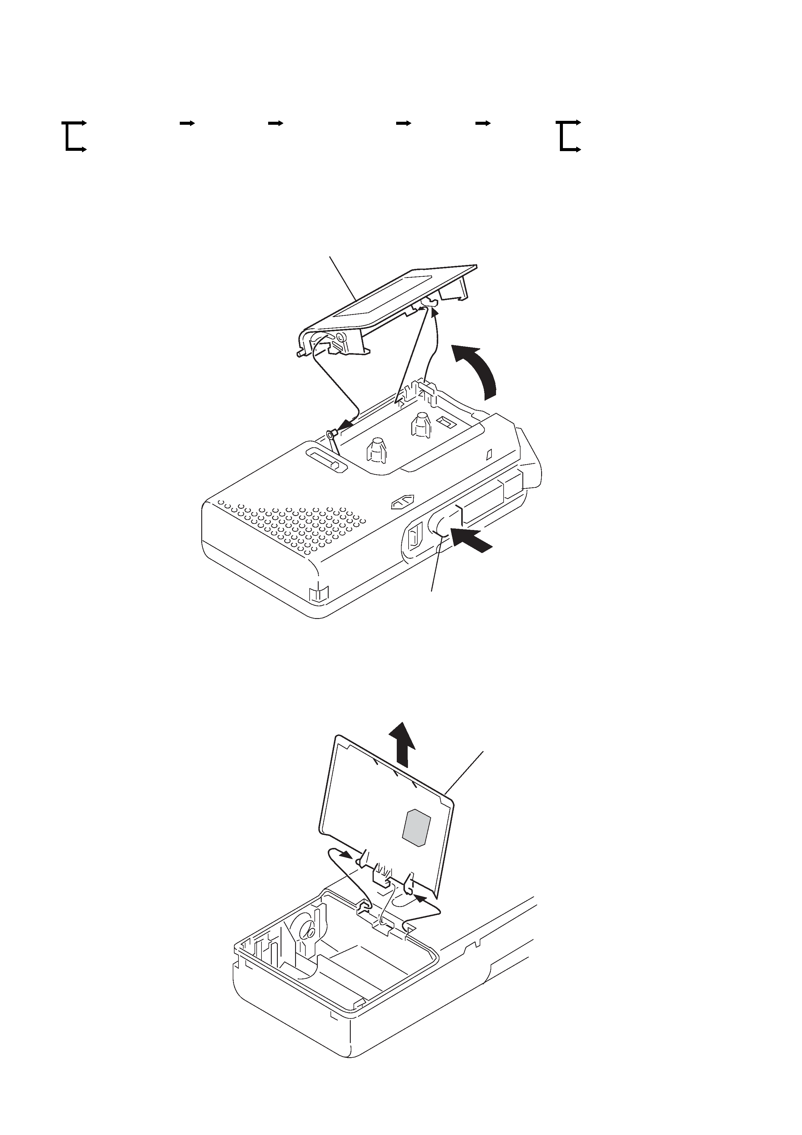
SECTION 2
DISASSEMBLY
· The equipment can be removed using the following procedure.
Note : Follow the disassembly procedure in the numerical order given.
2-1. LID ASSY, CASSETTE
2-2. LID, BATTERY CASE
Set
Lid assy, cassette
Head, ceramic
(HRPE901,902)
LED unit
Lid, battery case
Cabinet (rear)
assy
Main board
Mechanism
deck
Speaker, Microphone
(MIC901)
Lid assy, cassette
2 axis
3 axis
4 claw
5
1
Zp(Eject/Stop) button
Lid, battery case
1 claw
1 claw
2
5
M-740V
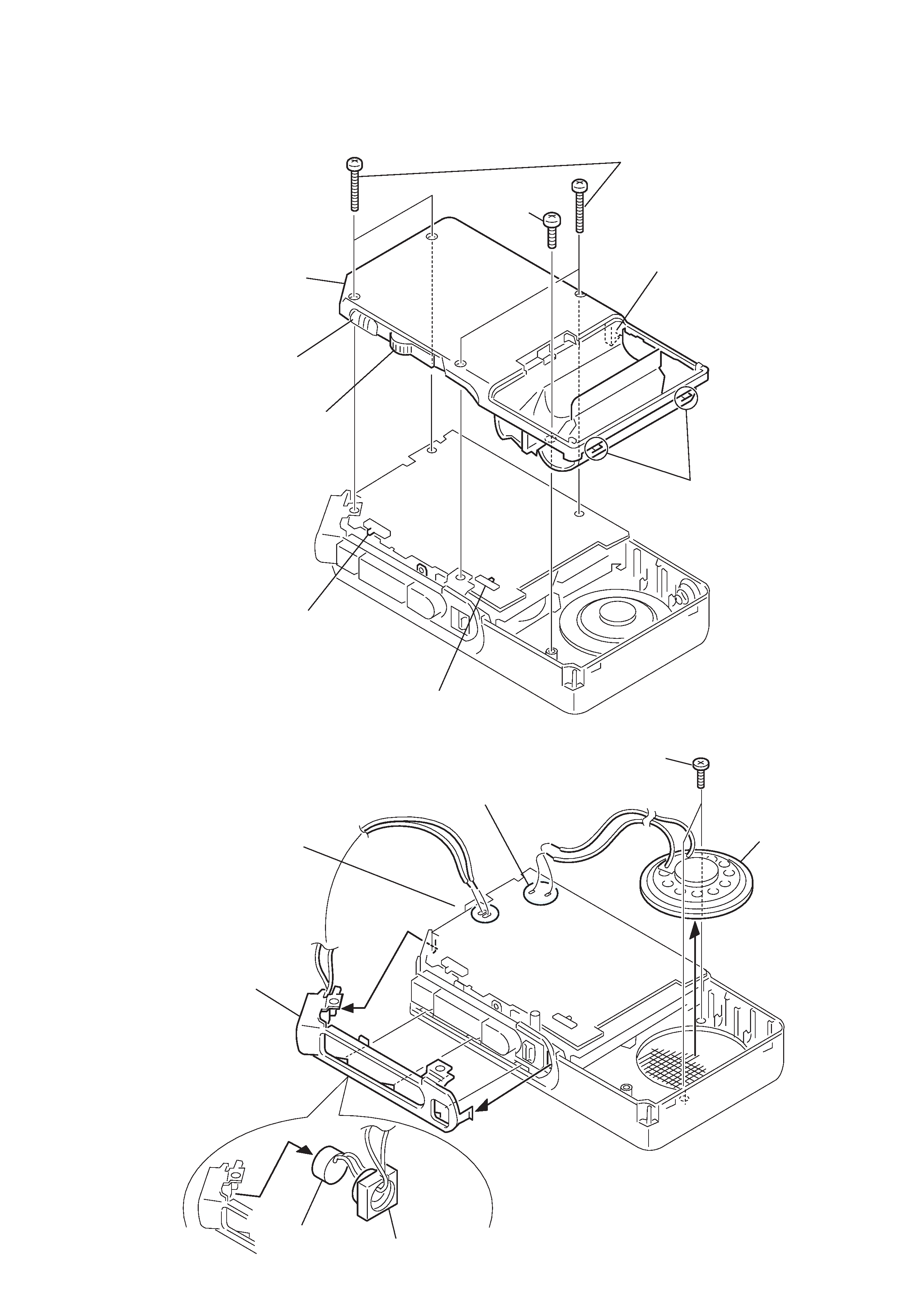
2-3. CABINET (REAR) ASSY
Note : When installing, fit the knobs and switches.
2-4. SPEAKER, MICROPHONE (MIC901)
2 Four screws
(B1.7
× 16)
1 Screw
(B1.7
× 5)
3 Claw
5 Cabinet
(rear) assy
4 Claws
Switch
(TAPE SPEED)
Switch
(PAUSE)
Knob
(PAUSE)
Knob
(FR)
4 Unsolder 2 places.
1 Unsolder 2 places.
2 Two screws
(B2
× 2.5)
3 Speaker
8 Microphone
(MIC901)
5 Holder (MIC)
6
7 Mic cushion