SERVICE MANUAL
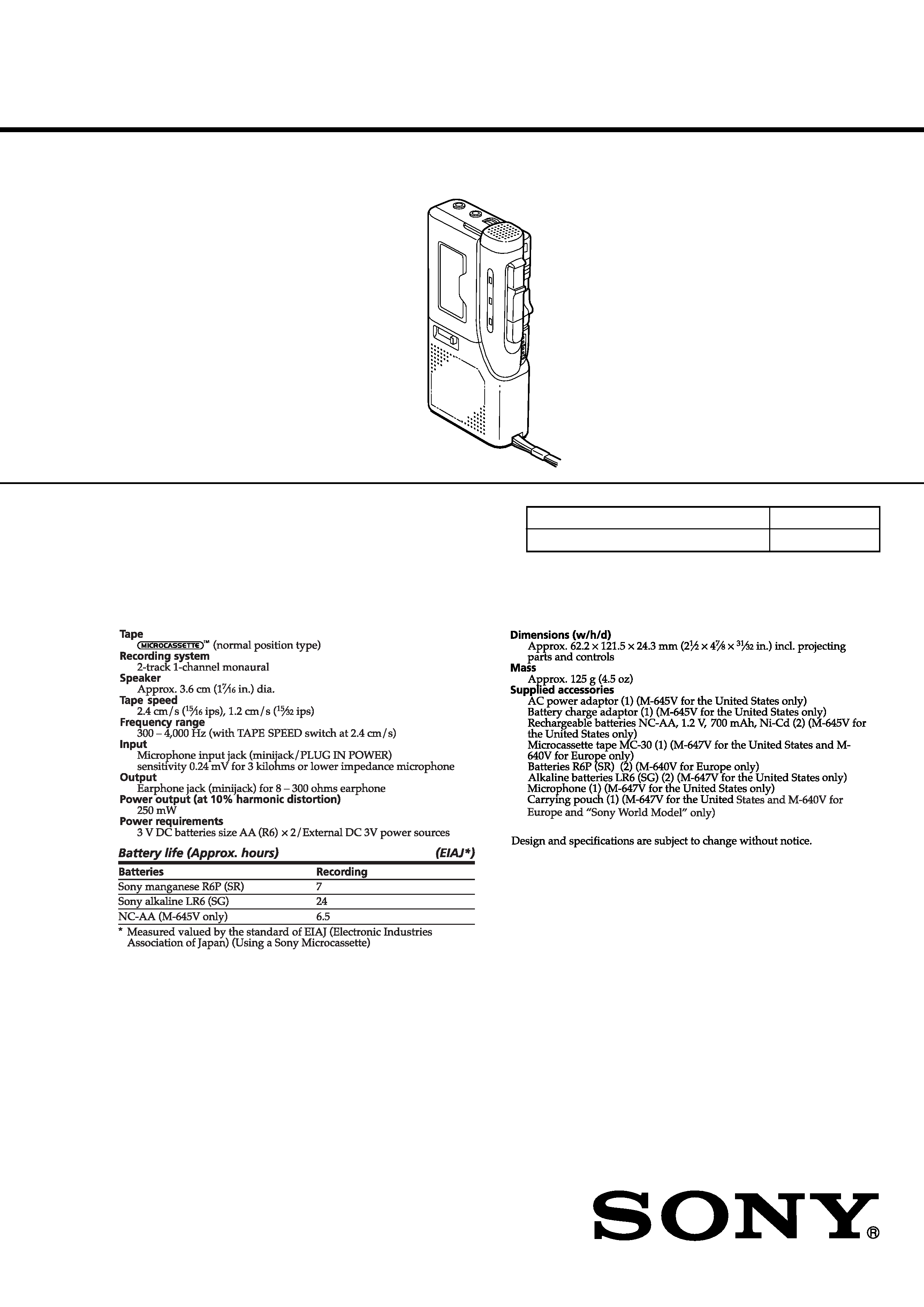
MICROCASSETTETM-CORDER
US Model
M-645V/647V
East European Model
E Model
Chinese Model
Tourist Model
M-640V
SPECIFICATIONS
M-640V/645V/647V
Ver 1.0 2001.02
9-873-059-11
Sony Corporation
2001B0500-1
Audio Entertainment Group
C
2001.2
General Engineering Dept.
Model Name Using Similar Mechanism
M-530V
Tape Transport Mechanism Type
MZ-530V-99
2
M-640V/645V/647V
TABLE OF CONTENTS
1.
GENERAL ................................................................... 3
2.
DISASSEMBLY
2-1. Disassembly Flow ...........................................................
4
2-2. Lid Assy, Cassette ...........................................................
4
2-3. Lid, Battery Case ............................................................
5
2-4. Cabinet (Rear) Assy ........................................................
5
2-5. MAIN Board ...................................................................
6
2-6. Mechanism Deck (MZ-530V-99) ...................................
6
2-7. LED Unit .........................................................................
7
2-8. Head, Ceramic (HRPE901) .............................................
7
3.
MECHANICAL ADJUSTMENTS ....................... 8
4.
ELECTRICAL ADJUSTMENTS ......................... 8
5.
DIAGRAMS
5-1. Block Diagram ................................................................ 11
5-2. Printed Wiring Board ...................................................... 12
5-3. Schematic Diagram ......................................................... 13
6.
EXPLODED VIEWS
6-1. Cabinet Section ............................................................... 14
6-2. Main Group Section ........................................................ 15
6-3. Mechanism Deck Section (MZ-530V-99) ...................... 16
7.
ELECTRICAL PARTS LIST ............................... 17
SAFETY-RELATED COMPONENT WARNING!!
COMPONENTS IDENTIFIED BY MARK 0 OR DOTTED
LINE WITH MARK 0 ON THE SCHEMATIC DIAGRAMS
AND IN THE PARTS LIST ARE CRITICAL TO SAFE
OPERATION. REPLACE THESE COMPONENTS WITH
SONY PARTS WHOSE PART NUMBERS APPEAR AS
SHOWN IN THIS MANUAL OR IN SUPPLEMENTS PUB-
LISHED BY SONY.
Flexible Circuit Board Repairing
· Keep the temperature of the soldering iron around 270°C dur-
ing repairing.
· Do not touch the soldering iron on the same conductor of the
circuit board (within 3 times).
· Be careful not to apply force on the conductor when soldering
or unsoldering.
Notes on Chip Component Replacement
· Never reuse a disconnected chip component.
· Notice that the minus side of a tantalum capacitor may be dam-
aged by heat.
3
M-640V/645V/647V
SECTION 1
GENERAL
This section is extracted from
instruction manual.
4
M-640V/645V/647V
· This set can be disassembled in the order shown below.
2-1.
DISASSEMBLY FLOW
SECTION 2
DISASSEMBLY
Note: Follow the disassembly procedure in the numerical order given.
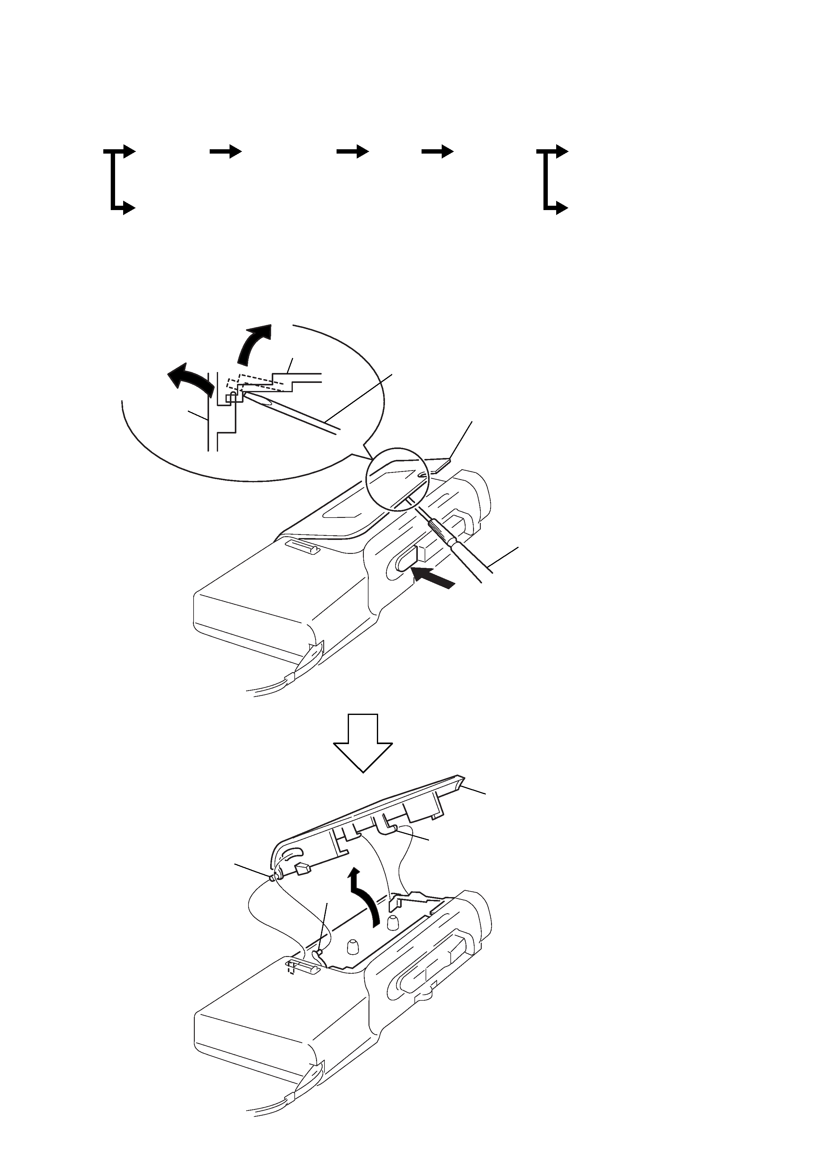
2-2.
LID ASSY, CASSETTE
Set
Lid Assy,
Cassette
Cabinet (rear)
Assy
Main
Board
Mechanism
Deck
(MZ-530V-99)
Head,
Ceramic (HRPE901)
LED
Unit
Lid,
Battery Case
2
Stop the "lid assy, cassette"
halfway.
1
3
4
precision screwdriver
or equivalent
cabinet (front)
lid assy,
cassette
top view
precision screwdriver
or equivalent
Note: When removing the cassette lid, put cloth on the end of a
screwdriver or use a polyacetal driver to avoid damage to
the cabinet.
9
lid assy, cassette
5
claw
8
6
boss
7
boss
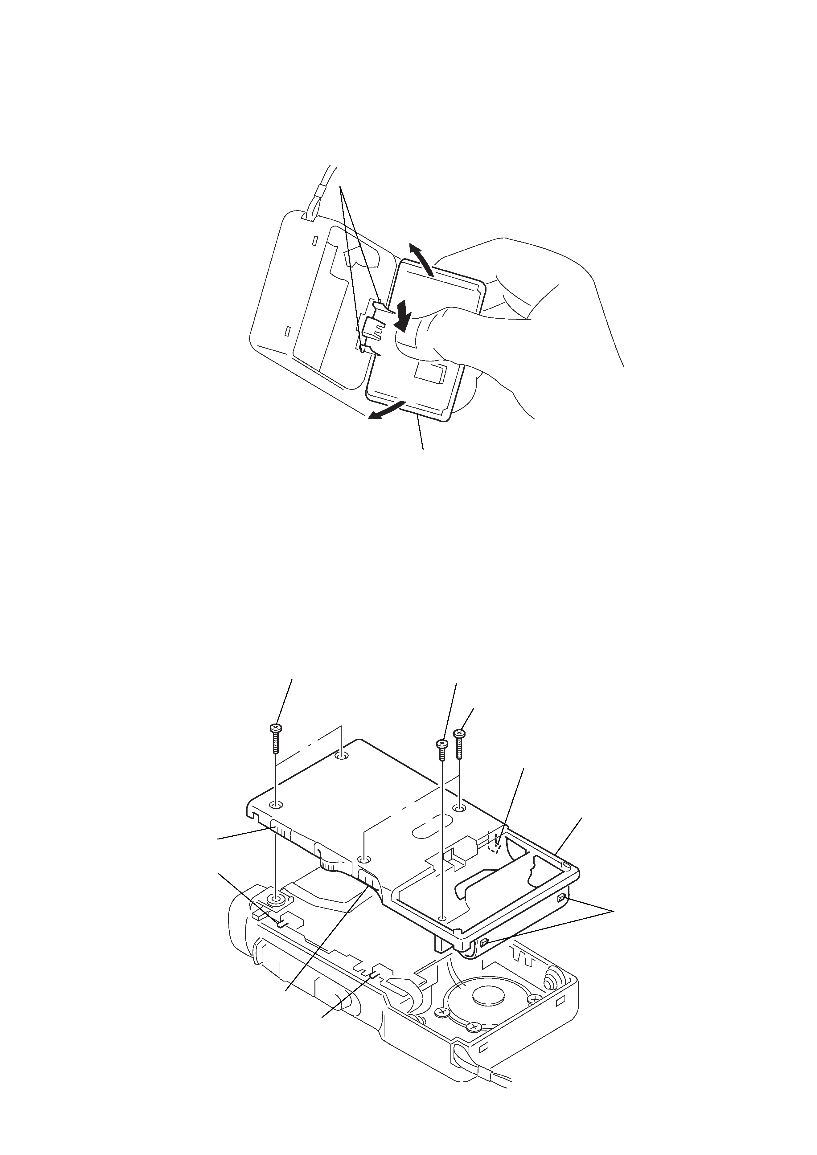
5
M-640V/645V/647V
2-3.
LID, BATTERY CASE
2-4.
CABINET (REAR) ASSY
Note: When installing, fit the knobs and switches.
3
two claws
4
lid, battery case
2
1
2
1
two screws (1.7x16)
3
screw (B1.7x5), tapping
2
two screws (1.7x16)
5
claw
4
two claws
switch
switch
knob
knob
6
cabinet (rear) assy