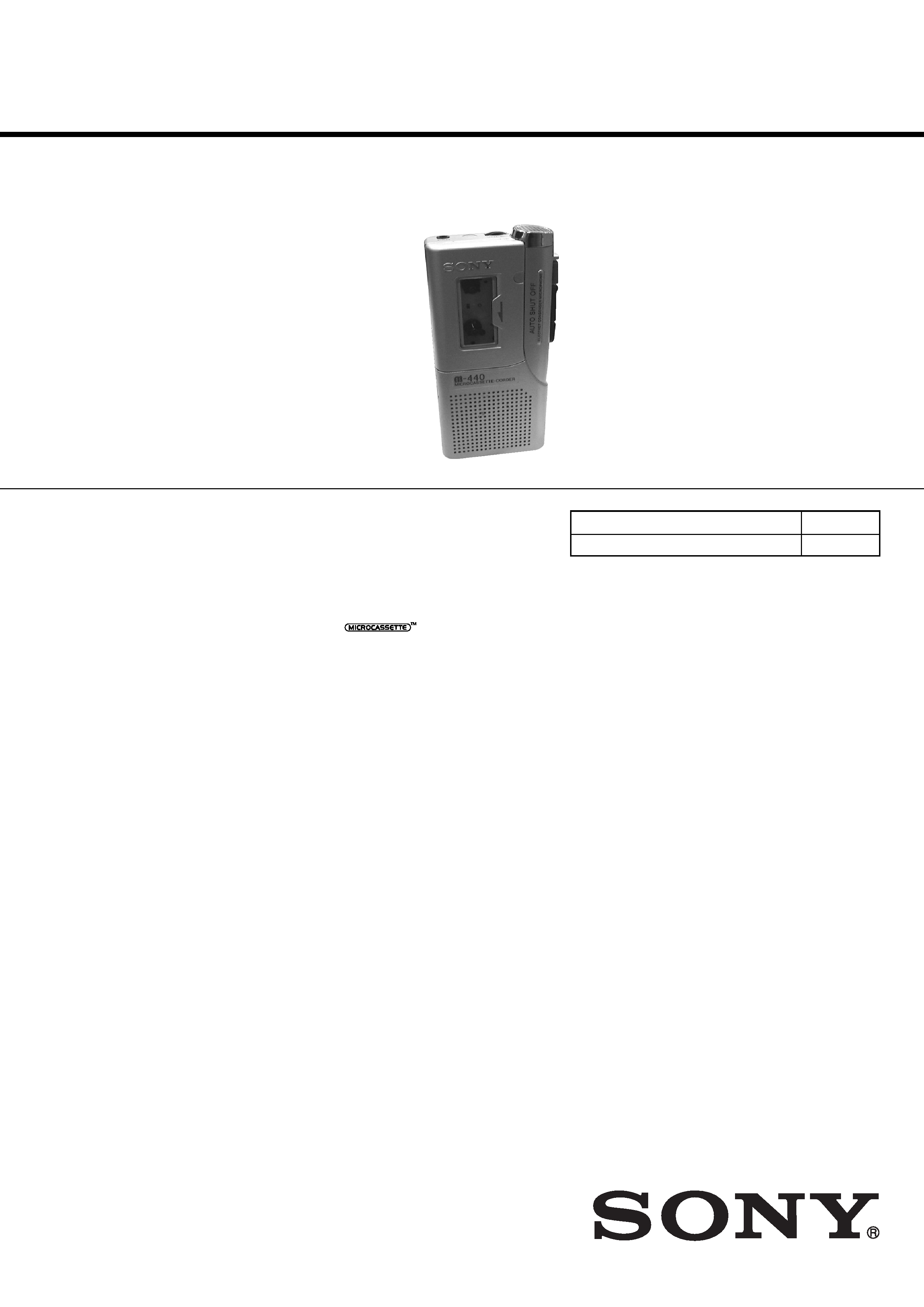
M-440
E Model
SERVICE MANUAL
MICROCASSETTETM-CORDER
Sony Corporation
Audio Entertainment Group
General Engineering Dept.
9-873-090-11
2001B1600-1
© 2001.2
SPECIFICATIONS
Ver 1.0 2001. 02
Model Name Using Similar Mechanism
M-430
Tape Transport Mechanism Type
MZ-430-99
Tape
(normal position type)
Recording system
2-track 1-channel monaural
Speaker
Approx. 3.6 cm (17/16 in.) dia.
Tape speed
2.4 cm/s (15/16 ips), 1.2 cm/s (15/32 ips)
Frequency range
300 - 4,000 Hz (with TAPE SPEED switch at 2.4 cm/s)
Output
Earphone jack (minijack) for 8 - 300 ohms earphone
Power output (at 10% harmonic distortion)
160 mW
Power requirements
3 V DC batteries R6 (size AA)
× 2/External DC 3V power sources
Dimensions (w/h/d)
Approx. 62.2
× 121.5 × 24.3 mm (21/2 × 47/8 × 31/32 in.) incl. projecting
parts and controls
Mass
Approx. 125 g (4.5 oz)
Supplied accessory
Microcassette tape MC-30 (1)
Design and specifications are subject to change without notice.

2
M-440
TABLE OF CONTENTS
Flexible Circuit Board Repairing
· Keep the temperature of the soldering iron around 270°C during
repairing.
· Do not touch the soldering iron on the same conductor of the
circuit board (within 3 times).
· Be careful not to apply force on the conductor when soldering
or unsoldering.
Notes on Chip Component Replacement
· Never reuse a disconnected chip component.
· Notice that the minus side of a tantalum capacitor may be dam-
aged by heat.
1. GENERAL .................................................................... 3
2. DISASSEMBLY
2-1. Lid Assy, Cassette .......................................................... 4
2-2. Lid, Battery Case ........................................................... 5
2-3. Cabinet (Rear) Assy ....................................................... 5
2-4. Main Board .................................................................... 6
2-5. Mechanism Deck ........................................................... 6
2-6. Head, Ceramic ............................................................... 7
3. MECHANICAL ADJUSTMENTS .............................. 8
4. ELECTRICAL ADJUSTMENTS ............................... 8
5. DIAGRAMS
5-1. Block Diagram .............................................................. 9
5-2. Printed Wiring Board ................................................... 10
5-3. Schematic Diagram ..................................................... 11
6. EXPLODED VIEWS
6-1. Cabinet Section ........................................................... 12
6-2. Mechanism Deck Section ............................................ 12
7. ELECTRICAL PARTS LIST ..................................... 13
3
M-440
SECTION 1
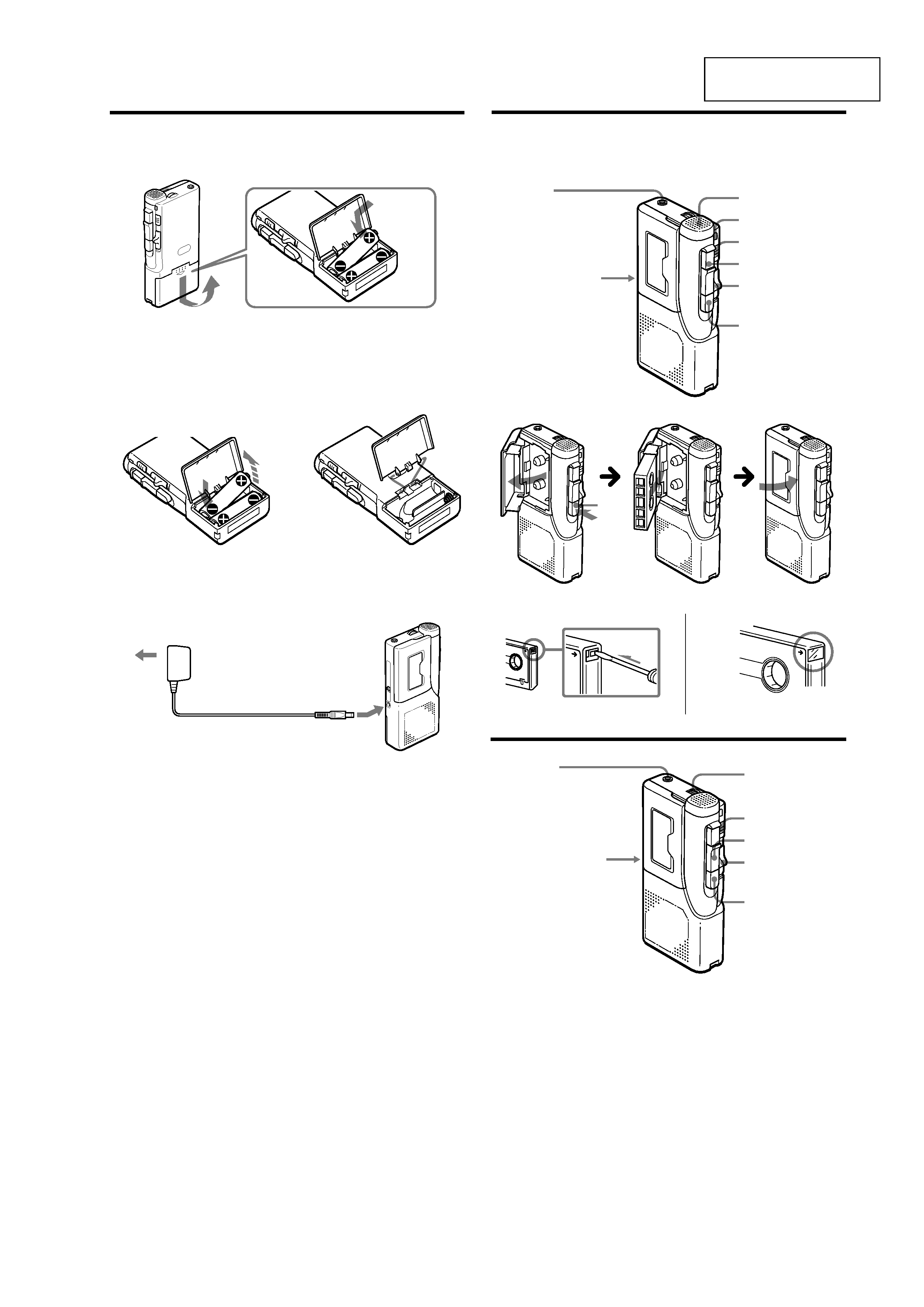
GENERAL
This section is extracted
from instruction manual.
A
(a)
B
(a)
C
(b)
(b)
AC power adaptor (not supplied)
Adaptateur secteur (non fourni)
Adaptador de CA (no suministrado)
Adattatore CA (non in dotazione)
Transformador de corrente CA (não fornecido)
Microphone
Microphone
Micrófono
Microfono
Microfone
BATT
z
>
PAUSE
m
CUE/
REVIEW M
xZ
EAR
VOL
n
>
PAUSE
m
CUE/
REVIEW M
xZ
(c)
(d)
to the wall outlet
vers prise murale
a toma de alimentación
a una presa di rete
para uma tomada de parede
EAR
TAPE SPEED
(c)
Insert the # side first for each battery.
Introduisez d'abord le côté # des piles.
Inserte primero el lado # para cada pila.
Inserire prima il lato # di ogni batteria.
Introduza primeiro o lado # de cada pilha.
TAPE SPEED
xZ
4
M-440
SECTION 2
DISASSEMBLY
· The equipment can be removed using the following procedure.
Note : Follow the disassembly procedure in the numerical order given.
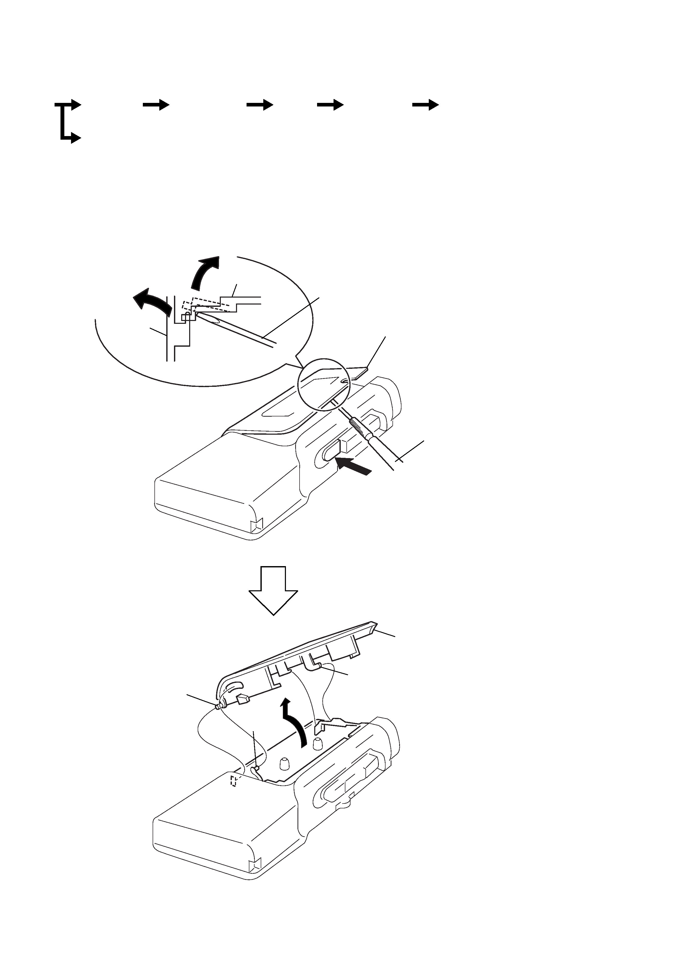
2-1. LID ASSY, CASSETTE
2 Stop the lid assy, cassette
halfway.
1
3
4
precision screwdriver
or equivalent
cabinet (front)
lid assy,
cassette
top view
precision screwdriver
or equivalent
9 lid assy, cassette
5 claw
8
6 axis
7 axis
Set
Lid assy,
cassette
Cabinet (rear)
assy
Main
board
Mechanism
deck
Head,
ceramic
Lid,
battery case
Note : When removing the cassette lid, put cloth on the end of a
screwdriver or use a polyacetal driver to avoid damage to
the cabinet.
5
M-440
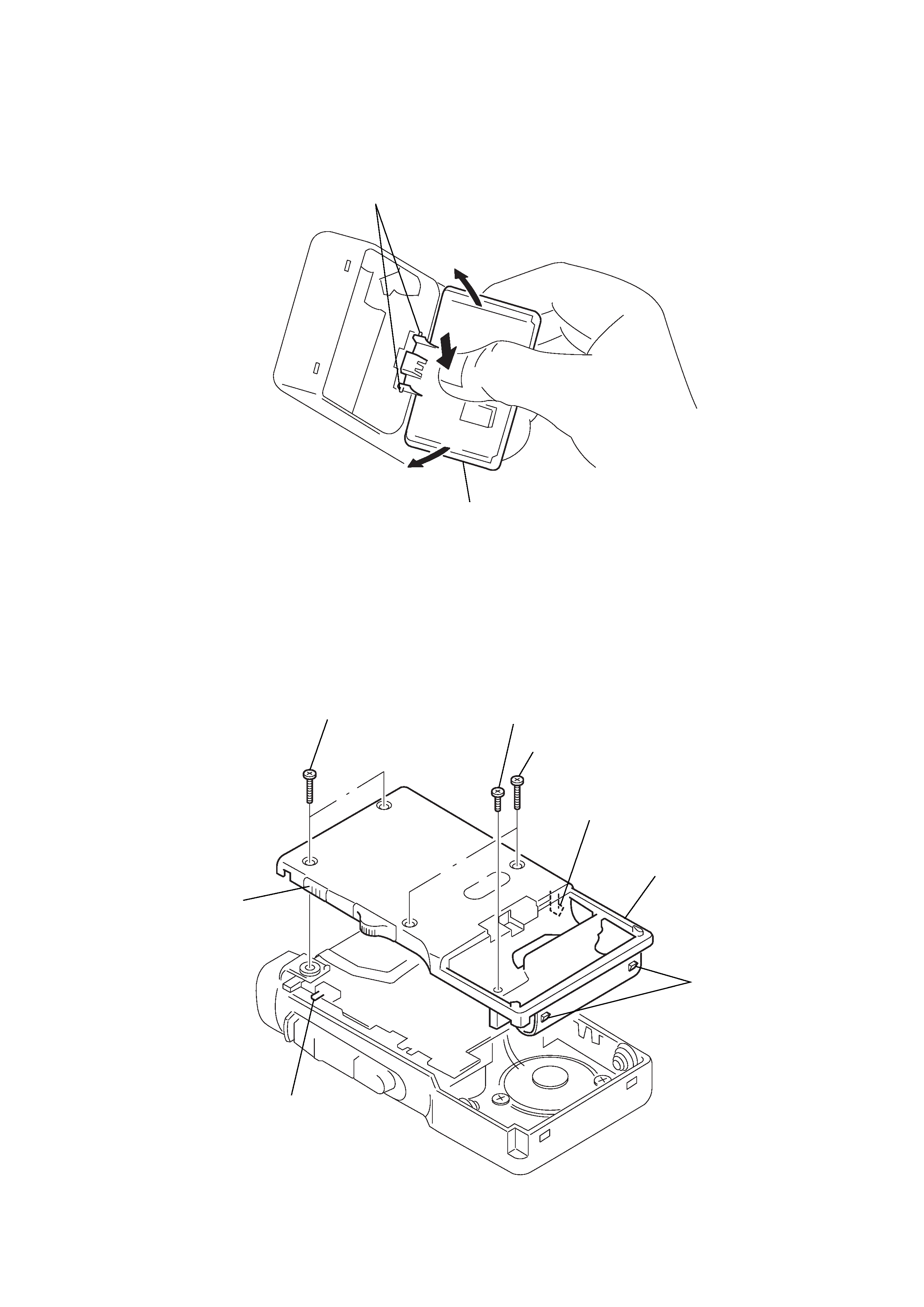
2-3. CABINET (REAR) ASSY
Note : When installing, fit the knobs and switches.
2-2. LID, BATTERY CASE
3 two claws
5 lid, battery case
2
1
2
1 two screws (1.7x16)
3 screw (B1.7x5), tapping
2 two screws (1.7x16)
5 claw
4 two claws
switch
knob
6 cabinet (rear) assy