1
SERVICE MANUAL
M-430
MICROCASSETTETM-CORDER
Tape
y (normal position type)
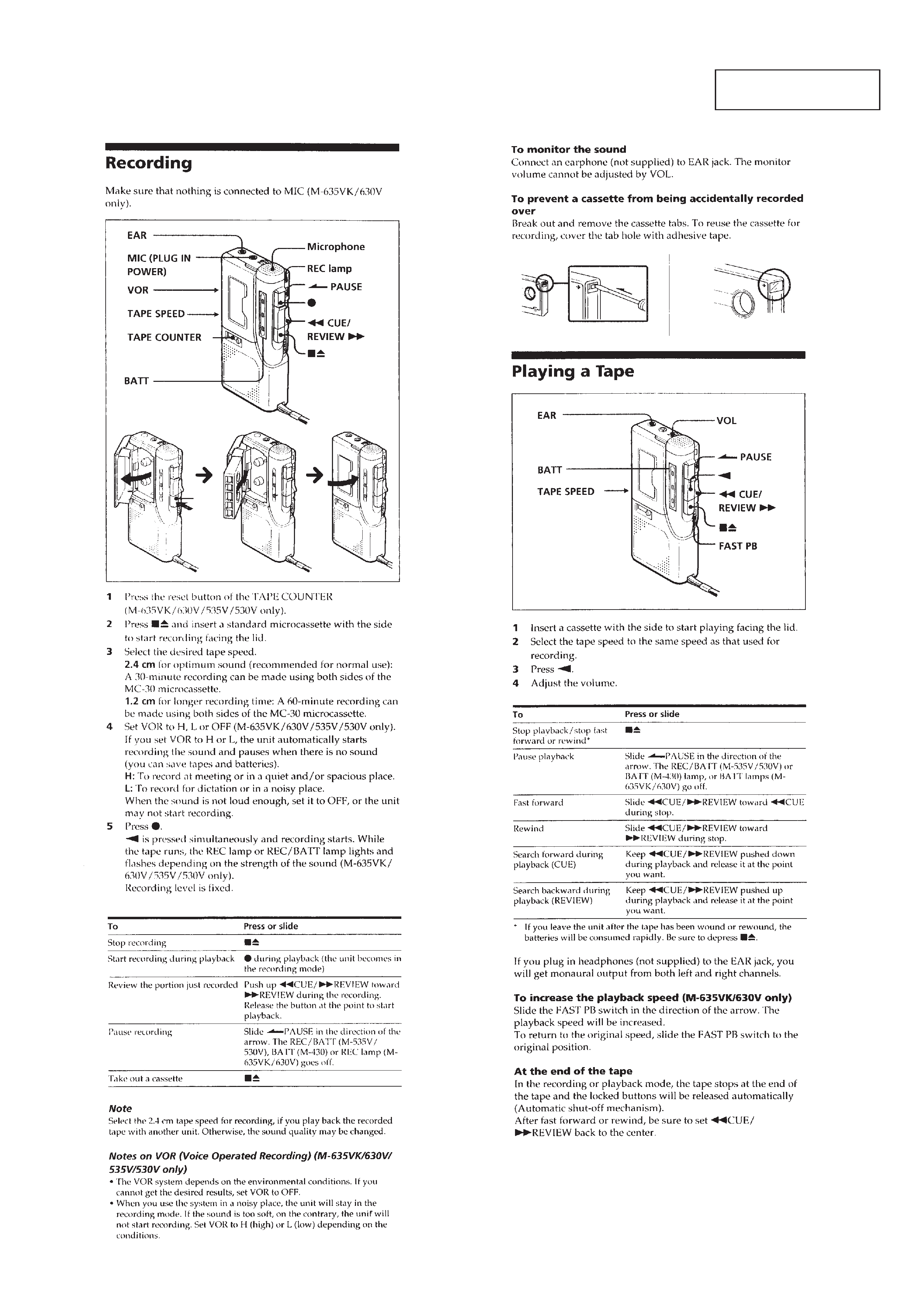
Recording system
2-track 1-channel monaural
Speaker
Approx. 3.6 cm (1 7/16 in.) dia.
Tape speed
2.4 cm/s (15/16 ips), 1.2 cm/s (15/32 ips)
Frequency range
250 - 4,000 Hz (with TAPE SPEED switch at 2.4 cm/s)
Output
Earphone jack (minijack) for 8 - 300 ohms earphone
Power output (at 10% harmonic distortion)
160 mW
Power requirements
3 V DC batteries size AA (R6)
× 2/External DC 3 V power sources
Dimensions (w/h/d)
Approx. 62.2
× 121.5 × 24.3 mm (2 1/2 × 4 7/8 × 31/32 in.) incl. projecting
parts and controls
Mass
Approx. 125 g (4.5 oz.)
SPECIFICATIONS
Ver 1.2 1999. 05
With SUPPLEMENT-1
(9-926-960-81)
With SUPPLEMENT-2
(9-926-960-82)
Supplied accessory
Microcassette tape MC-30 (1)
Design and specifications are subject to change without notice.
MICROFILM
US Model
AEP Model
E Model
Model Name Using Similar Mechanism
NEW
Tape Transport Mechanism Type
MZ-430-99

2
TABLE OF CONTENTS
Flexible Circuit Board Repairing
· Keep the temperature of the soldering iron around 270°C during
repairing.
· Do not touch the soldering iron on the same conductor of the
circuit board (within 3 times).
· Be careful not to apply force on the conductor when soldering
or unsoldering.
Notes on Chip Component Replacement
· Never reuse a disconnected chip component.
· Notice that the minus side of a tantalum capacitor may be dam-
aged by heat.
1. GENERAL .................................................................... 3
2. DISASSEMBLY
2-1. Lid Assy, Cassette ............................................................... 4
2-2. Lid, Battery Case ................................................................ 5
2-3. Cabinet (Rear) Assy ............................................................ 5
2-4. Main Board ......................................................................... 6
2-5. Mechanism Deck ................................................................. 6
2-6. Head, Ceramic ..................................................................... 7
3. MECHANICAL ADJUSTMENTS .............................. 8
4. ELECTRICAL ADJUSTMENTS ............................... 8
5. DIAGRAMS
5-1. Block Diagram .................................................................. 10
5-2. Printed Wiring Board ........................................................ 11
5-3. Schematic Diagram ........................................................... 13
6. EXPLODED VIEWS
6-1. Cabinet Section ................................................................. 15
6-2. Mechanism Deck Section .................................................. 16
7. ELECTRICAL PARTS LIST ..................................... 17
3
SECTION 1
GENERAL
This section is extracted
from instruction manual.
4
SECTION 2
DISASSEMBLY
· The equipment can be removed using the following procedure.
Note : Follow the disassembly procedure in the numerical order given.
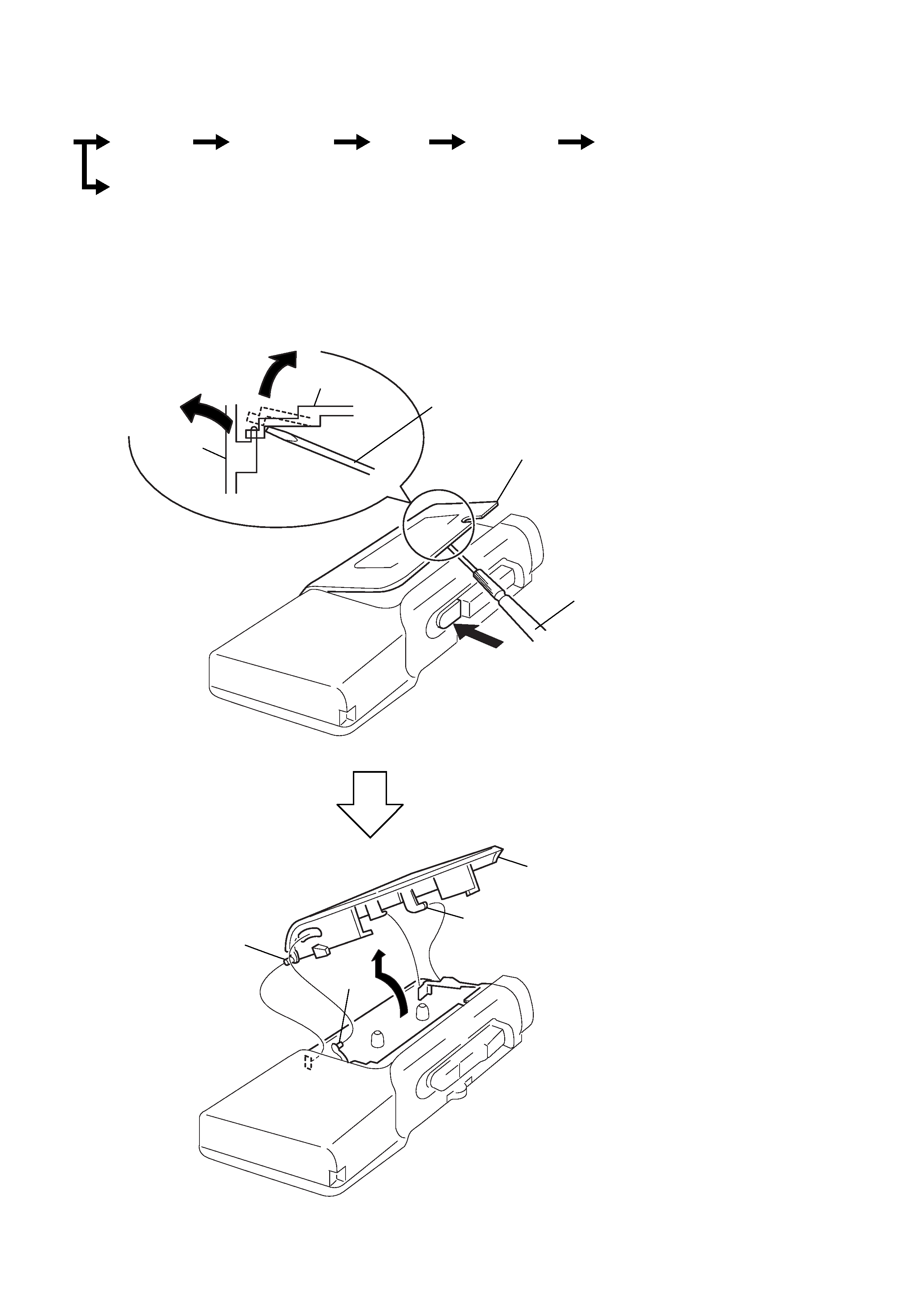
2-1. LID ASSY, CASSETTE
2 Stop the lid assy, cassette
halfway.
1
3
4
precision screwdriver
or equivalent
cabinet (front)
lid assy,
cassette
top view
precision screwdriver
or equivalent
9 lid assy, cassette
5
8
6
7
Set
Lid assy,
cassette
Cabinet (rear)
assy
Main
board
Mechanism
deck
Head,
ceramic
Lid,
battery case
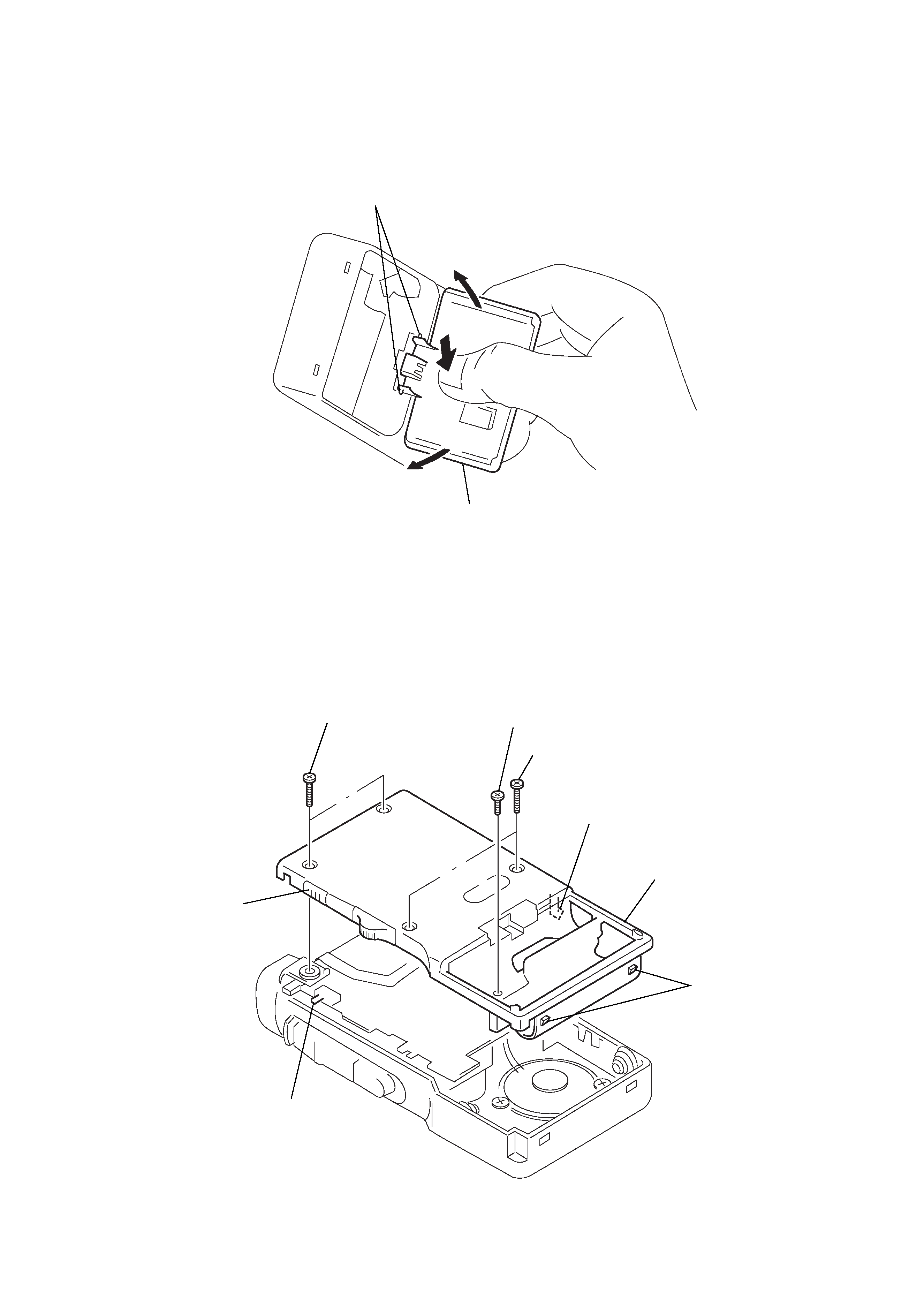
Note : When removing the cassette lid, put cloth on the end of a
screwdriver or use a polyacetal driver to avoid damage to
the cabinet.
5
2-3. CABINET (REAR) ASSY
Note : When installing, fit the knobs and switches.
2-2. LID, BATTERY CASE
3 claws
5 lid, battery case
2
1
2
1 screw (1.7x16)
3 screw (B1.7x5), tapping
2 screw (1.7x16)
5 claw
4 claws
switch
knob
6 cabinet (rear) assy