SERVICE MANUAL
Sony Corporation
Home Audio Division Company
COMPACT Hi-Fi STEREO SYSTEM
2000B001670-1
Printed in Japan ©2000.2
Published by Quality Assurance Dept.
9-929-076-11
AEP Model
UK Model
LBT-LX7
E Model
LBT-LX7/LX8
Australian Model
LBT-LX8
COMPONENT MODEL NAME FOR LBT-LX7/LX8
· LBT-LX7 / LX8 is composed following models.
As for the service manual, it is issued for each component model,
then, please refer to it.
COMPACT DISC DECK
RECEIVER SYSTEM
SPEAKER SYSTEM
SS-LX7
PARTS LIST
Part No.
Description
Remark
ACCESSORIES & PACKING MATERIALS
********************************
1-475-572-41 COMMANDER, STANDARD (RM-SR5B)
1-501-374-11 ANTENNA, LOOP
1-501-659-41 ANTENNA (FM) (LBT-LX8)
1-501-804-11 ANTENNA (FM) (LBT-LX7)
1-775-512-21 CORD, SPEAKER
4-227-074-11 MANUAL, INSTRUCTION (ENGLISH)
4-227-074-21 MANUAL, INSTRUCTION (FRENCH) (EA)
4-227-074-31 MANUAL, INSTRUCTION (SPANISH) (AR, MX)
4-227-074-41 MANUAL, INSTRUCTION (FRENCH, SPANISH) (AEP)
4-227-074-51 MANUAL, INSTRUCTION ( GERMAN, DUTCH, SWEDISH) (AEP)
4-227-074-61 MANUAL, INSTRUCTION (ITALIAN, PORTUGUESE) (AEP)
4-227-074-71 MANUAL, INSTRUCTION (POLISH, RUSSIAN) (CIS)
4-227-074-81 MANUAL, INSTRUCTION (ARABIC) (EA)
4-227-074-91 MANUAL, INSTRUCTION (CHINESE)(SP, MY)
4-227-075-11 MANUAL, INSTRUCTION (CZECH) (CIS)
4-227-075-21 MANUAL, INSTRUCTION (HUNGARIAN) (CIS)
4-227-075-31 MANUAL, INSTRUCTION (GREEK ) (CIS)
4-227-075-41 MANUAL, INSTRUCTION (TURKISH) (CIS)
4-228-574-11 MANUAL, INSTRUCTION(ENGLISH, FRENCH, GERMAN, SPANISH,
DUTCH, SWEDISH, ITALIAN, PORTUGUESE, POLISH, RUSSIAN,
DANISH, FINNISH, HUNGARIAN, CZECH, GREEK, TURKISH)(SS-LX7)
4-210-254-01 CUSHION (FOOT)
4-991-151-31 COVER, BATTERY (FOR RM-SR5B)
LBT-LX7/LX8
HCD-LX7
LBT-LX7
LBT-LX8
HCD-LX8
SS-LX8
SPECIFICATIONS
General
Power requirements
European model:
230 V AC, 50 / 60 Hz
Mexican model:
120 V AC, 50 / 60 Hz
Australian models:
230 - 240 V AC, 50 / 60 Hz
Other models:
120 V, 220V, or 230 - 240 V AC,
50 / 60 Hz
Adjustable with voltage selector
Power consumption
(LBT-LX7)
220 watts
(LBT-LX8)
300 watts
Supplied accessories
AM loop antenna (1)
Remote RM-SR5B (1)
R6 (size AA) batteries (2)
FM wire antenna (1)
Speaker cords (2)
Design and specifications are subject to change without notice.
· Abbreviation
CND : Canadian model
MX : Mexican model
EA
: Saudi Arabia model
AR
: Argentine model
SP
: Singapore model
MY : Malaysia model
1
HCD-LX7/LX8
AEP Model
UK Model
HCD-LX7
E Model
Australian Model
HCD-LX8
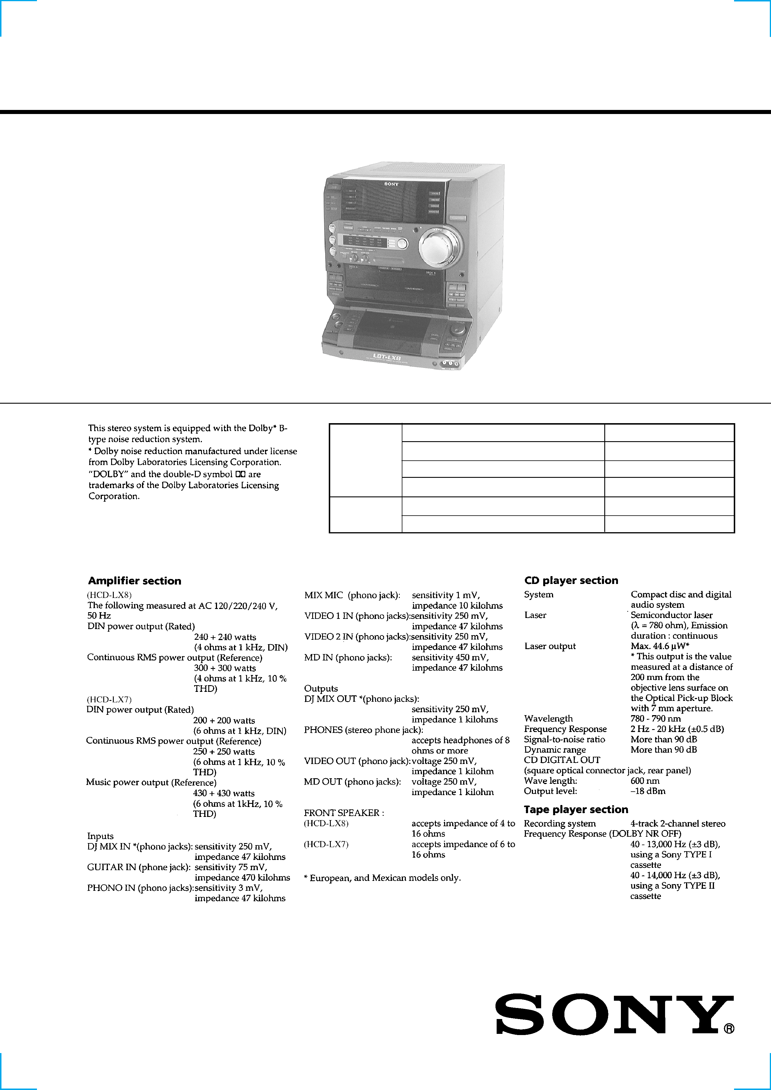
SPECIFICATIONS
Photo: HCD-LX8
COMPACT HiFi STEREO SYSTEM
-- Continued on next page --
Model Name Using Similar Mechanism
HCD-DR4/XB500
CD Mechanism Type
CDM37M-5BD32L
Base Unit Type
BU-5BD32L
Optical Pick-up Type
KSS-213D/Q-NP
Model Name Using Similar Mechanism
HCD-GRX10AV/RX110AV
Tape Transport Mechanism Type
TCM-230PWR1
CD
SECTION
TAPE DECK
SECTION
SERVICE MANUAL
HCD-LX7/LX8 is the tuner, deck, CD and
amplifier section in LBT-LX7/LX8.
2
CAUTION
Use of controls or adjustments or performance of procedures
other than those specified herein may result in hazardous ra-
diation exposure.
Notes on chip component replacement
· Never reuse a disconnected chip component.
· Notice that the minus side of a tantalum capacitor may be
damaged by heat.
Flexible Circuit Board Repairing
· Keep the temperature of soldering iron around 270°C
during repairing.
· Do not touch the soldering iron on the same conductor of the
circuit board (within 3 times).
· Be careful not to apply force on the conductor when soldering
or unsoldering.
SAFETY-RELATED COMPONENT WARNING !!
COMPONENTS IDENTIFIED BY MARK 0 OR DOTTED LINE
WITH MARK 0 ON THE SCHEMATIC DIAGRAMS AND IN
THE PARTS LIST ARE CRITICAL TO SAFE OPERATION.
REPLACE THESE COMPONENTS WITH SONY PARTS
WHOSE PART NUMBERS APPEAR AS SHOWN IN THIS
MANUAL OR IN SUPPLEMENTS PUBLISHED BY SONY.
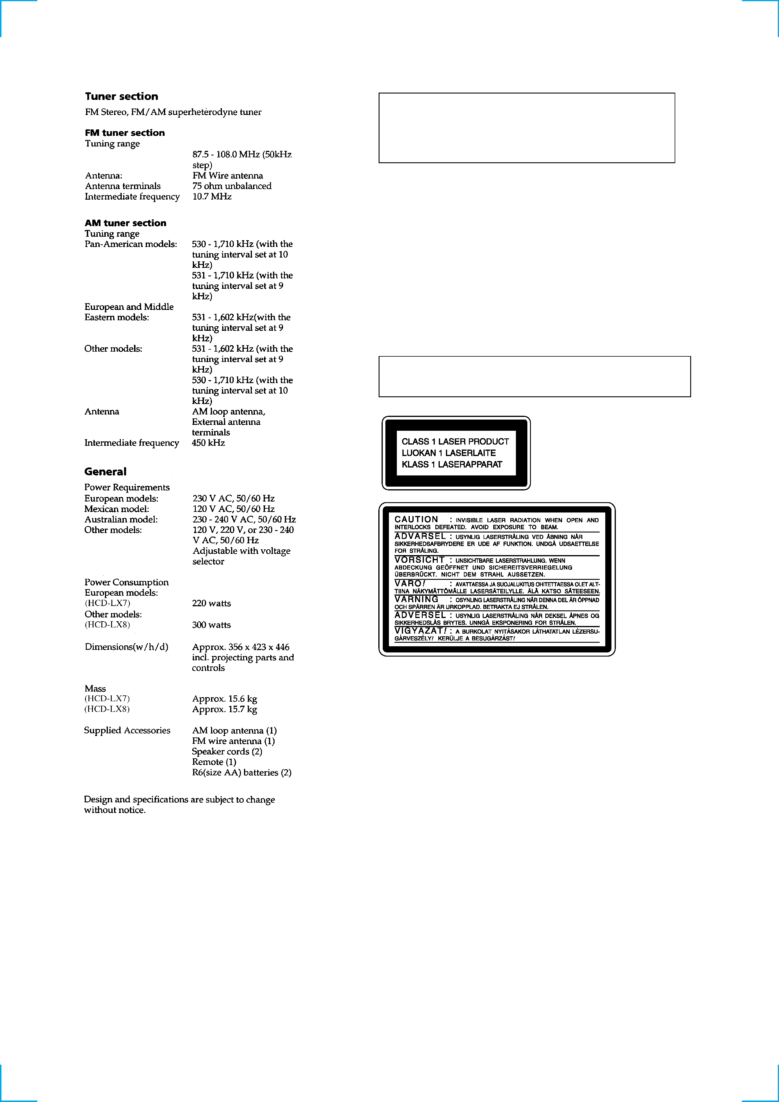
Laser component in this product is capable of emitting radiation
exceeding the limit for Class 1.
This appliance is classified as
a CLASS 1 LASER product.
The CLASS 1 LASER PROD-
UCT MARKING is located on
the rear exterior.
This caution
label is located
inside the unit.
3
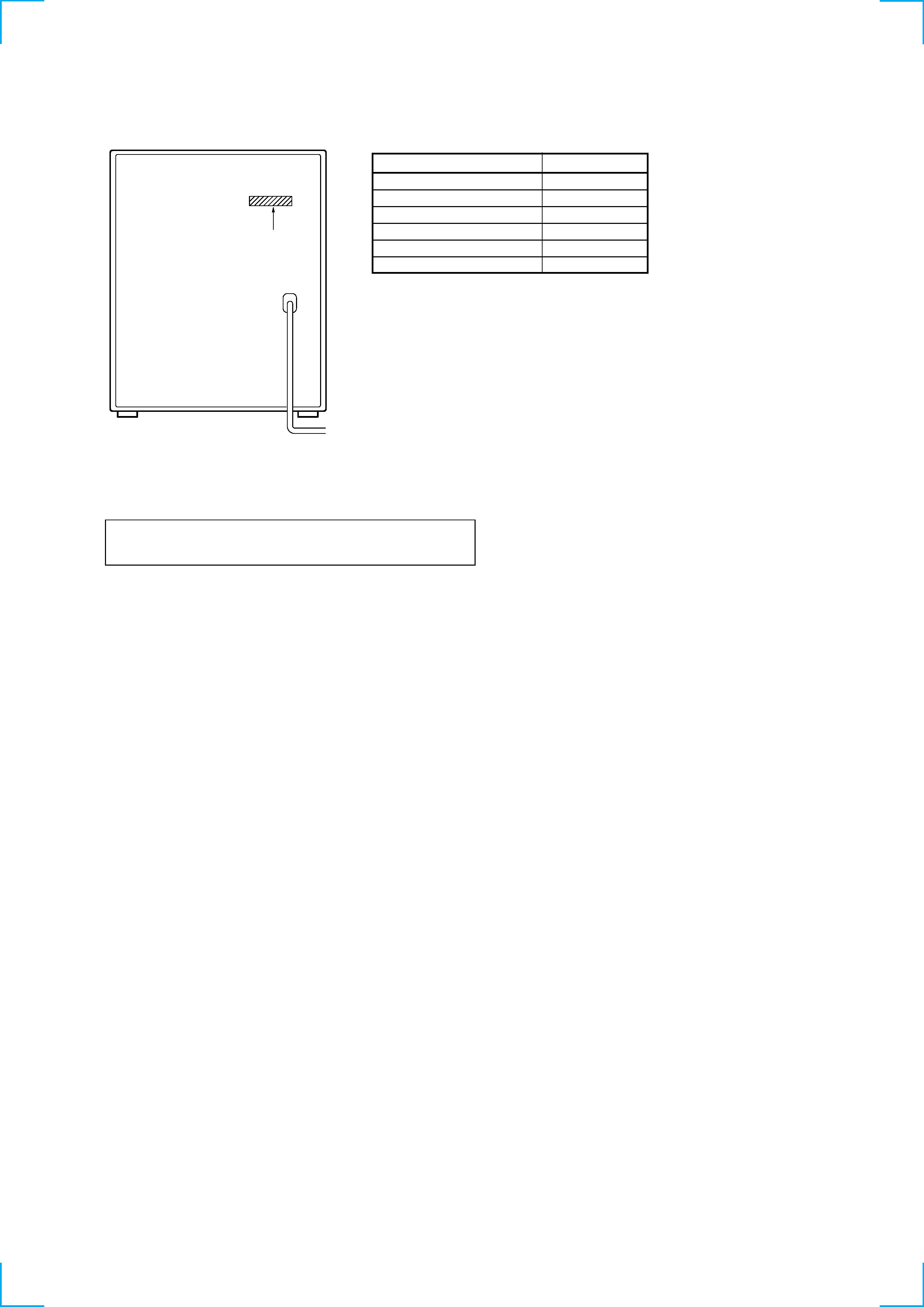
MODEL
PARTS No.
LX7: AEP, UK, CIS model
4-225-529-1s
LX8: E, AR model
4-225-529-2s
LX8: SP, MY model
4-225-529-3s
LX8: MX model
4-225-529-4s
LX8: AUS model
4-225-529-5s
LX8: EA model
4-225-529-6s
NOTES ON HANDLING THE OPTICAL PICK-UP BLOCK
OR BASE UNIT
The laser diode in the optical pick-up block may suffer electrostatic
break-down because of the potential difference generated by the
charged electrostatic load, etc. on clothing and the human body.
During repair, pay attention to electrostatic break-down and also
use the procedure in the printed matter which is included in the
repair parts.
The flexible board is easily damaged and should be handled with
care.
NOTES ON LASER DIODE EMISSION CHECK
The laser beam on this model is concentrated so as to be focused on
the disc reflective surface by the objective lens in the optical pick-
up block. Therefore, when checking the laser diode emission, ob-
serve from more than 30 cm away from the objective lens.
LASER DIODE AND FOCUS SEARCH OPERATION
CHECK
Carry out the "S curve check" in "CD section adjustment" and check
that the S curve waveform is output four times.
MODEL IDENTIFICATION
-- BACK PANEL --
· Abbreviation
SP
: Singapore model
MX
: Mexican model
AUS : Australian model
EA
: Saudi Arabia model
AR
: Argentine model
MY
: Malaysia model
Parts No.

4
7. EXPLODED VIEWS
7-1. Case and Back Panel Section .............................................. 53
7-2. Front Panel Section 1 .......................................................... 54
7-3. Front Panel Section 2 .......................................................... 55
7-4. Chassis Section ................................................................... 56
7-5. TC Mechanism Section 1 (TCM230PWR1) ....................... 57
7-6. TC Mechanism Section 2 (TCM230PWR1) ....................... 58
7-7. CD Mechanism Section (CDM37M-5BD32L) ................... 59
7-8. Base Unit Section (BU-5BD32L) ....................................... 60
8. ELECTRICAL PARTS LIST ........................................ 61
1. SERVICING NOTE .......................................................... 5
2. GENERAL .................................................................... 9
3. DISASSEMBLY
3-1. Front Panel .......................................................................... 11
3-2. Main Board ......................................................................... 11
3-3. Sub Panel ............................................................................ 12
3-4. CD LID Assembly .............................................................. 12
3-5. Tape Mechanism Deck and Cassette LID ........................... 12
3-6. CD Mechanism Deck .......................................................... 13
3-7. Base Unit ............................................................................. 13
3-8. Disc Table ........................................................................... 13
4. MECHANICAL ADJUSTMENTS .......................... 14
5. ELECTRICAL ADJUSTMENTS ............................... 14
6. DIAGRAMS
6-1. Circuit Boards Location ...................................................... 17
6-2. Block Diagrams
· BD (CD) Section .............................................................. 18
· Deck Section .................................................................... 19
· Main (1/2) Section ........................................................... 20
· Main (2/2) Section ........................................................... 21
· Power Section (LX8 model) ............................................ 22
· Power Section (LX7 model) ............................................ 23
· Display Section ................................................................ 24
6-3. Printed Wiring Board BD (CD) Section ....................... 26
6-4. Schematic Diagram BD (CD) Section .......................... 27
6-5. Printed Wiring Board Main Section .............................. 28
6-6. Schematic Diagram Main (1/3) Section ........................ 29
6-7. Schematic Diagram Main (2/3) Section ........................ 30
6-8. Schematic Diagram Main (3/3) Section ........................ 31
6-9. Schematic Diagram Deck Section ................................. 32
6-10. Printed Wiring Board Deck Section ........................... 33
6-11. Schematic Diagram Power Section ............................ 34
6-12. Printed Wiring Board Power Section ......................... 35
6-13. Schematic Diagram Panel FL Section ........................ 36
6-14. Printed Wiring Board Panel FL Section ..................... 37
6-15. Schematic Diagram Panel VR Section ....................... 38
6-16. Printed Wiring Board Panel VR Section .................... 39
6-17. Schematic Diagram TC Panel Section ....................... 40
6-18. Printed Wiring Board TC Panel Section ..................... 41
6-19. Schematic Diagram CD Panel Section ....................... 42
6-20. Printed Wiring Board CD Panel Section .................... 43
6-21. Schematic Diagram CD Motor Section ...................... 44
6-22. Printed Wiring Board CD Motor Section ................... 45
6-23. Schematic Diagram Trans Section (LX7 model) ....... 46
6-24. Printed Wiring Board Trans Section (LX7 model) ..... 47
6-25. Schematic Diagram Trans Section (LX8 model) ....... 48
6-26. Printed Wiring Board Trans Section (LX8 model) ..... 49
6-27. Schematic Diagram Leaf SW Section ........................ 49
6-28. Printed Wiring Board Leaf SW Section ..................... 49
6-29. IC Block Diagrams ........................................................... 50
6-30. IC Pin Functions ............................................................... 50
TABLE OF CONTENTS